skilleye SEC-8P3562IRT User manual

SEC-8P3562IRT
WARNINGS AND CAUTIONS
WARNING
TO REDUCE THE RISK OF FIRE OR ELECTRIC SHOCK, DO NOT EXPOSE THIS
PRODUCT TO RAIN OR MOISTURE. DO NOT INSERTANYMETALLIC OBJECTS THROUGH
VENTILATION GRILLS OR OPENINGS ON THE EQUIPMENT.
CAUTION
EXPLANATION OF GRAPHICAL SYMBOLS
The lighting flash with arrowhead symbol, within an equilateral triangle, is intended to
alert the user the presence of non-insulated “dangerous voltage” within the product’s
enclosure that maybe of sufficient magnitude to constitute a risk of electric shock to
different persons.
The exclamation point within an equilateral triangle, is intended to alert the user the
presence of important operating and maintenance (servicing) instructions in the
literature accompanying this product.

PRECAUTIONS:
1. Persons without technical qualifications should not attempt to operate this dome device before
reading this manual thoroughly.
2. Remove any power to the dome before attempting any operations or adjustments inside the
dome cover to avoid potential damage to the mechanism.
3. Inside the dome cover there are precision optical and electrical devices. Heavy pressure,
shock and other sudden adjustments or operations should be avoided. Otherwise, you may
cause irreparable damage to the product.
4. Please DO NOT remove or disassemble any internal parts of the video camera to avoid
normal operation and possibly void the warranty. There are no serviceable parts inside the
camera.
5. All electrical connections to the dome should be made in strict accordance with the attached
labels and wiring instructions in this manual. Failure to do so may damage the dome beyond
repair and void the warranty.
6. For outdoor installation especially in high places or poles, it is highly recommended that the
proper lightning arrestors and surge suppressors are installed before the dome is entered into
service.
7. Please do not use the product under circumstances where the limits exceed the maximum
specified temperature, humidity or power supply specifications.

IMPORTANT SAFEGUARDS
1. Read these instructions before attempting installation or operation of dome device.
2. Keep these instructions for future reference.
3. Heed all warnings and adhere to electrical specifications. Follow all instructions.
4. Clean only with non abrasive dry cotton cloth, lint free and approved acrylic cleaners.
5. Should the lens of the camera become dirty, use special lens cleaning cloth and solution to
properly clean it.
6. Do not block any ventilation openings. Install in accordance with manufacturer’s instructions.
7. Use only attachments or accessories specified by the manufacturer.
8. Verify that the surface you are planning to use for attaching the dome can adequately support
the weight of the device and mounting hardware.
9. Protect this device against lighting storms with proper power supplies.
10. Refer all servicing to qualified service personnel. Servicing is required when the device has
been damaged in any way, when liquid traces are present, or the presence of loose objects is
evident or if the device does not function properly, or has received sever impact or has been
dropped accidentally.
11. Indoor dome is for indoor use only and not suitable for outdoor or high humidity locations.
Do not use this product under circumstances exceeding specified temperature and humidity
ratings.
12. Avoid pointing the camera directly to the sun or other extremely bright objects for prolonged
period of time avoiding the risk of permanent damages to the imaging sensor.
13. The attached instructions are for use by qualified personnel only. To reduce the risks of
electric shock, do not perform any servicing other than contained in the operating instructions
unless you are qualified to do so.
14. During usage, user should abide by all electrical safety standards and adhere to electrical
specifications for the operation of the dome. The control cable for RS485 communications as
well as the video signal cables should be isolated from high voltage equipment and high voltage
cables.
15. Use supplied power supply transformer only.

INDEX
1 Product Introduction ......................................................................................................1
1.1 Package Contents......................................................................................................1
1.2 Specification...............................................................................................................2
1.3 Performance Features................................................................................................3
1.4 Function Description...................................................................................................4
2 Installation.......................................................................................................................6
2.1 Product Dimension............................................Errore. Il segnalibro non è definito.
2.2 Bracket Dimension.....................................................................................................7
2.3 Installation.........................................................Errore. Il segnalibro non è definito.
2.4 Connection...............................................................................................................12
3. Instruction ....................................................................................................................13
3.1 Power On Action.......................................................................................................13
3.2 Basic Function..........................................................................................................13
3.3 Special Function.......................................................................................................14
3.4 Screen Character Operation ....................................................................................15
4 OSD Menu......................................................................................................................16
4.1 System.....................................................................................................................17
4.2 Dome Function.........................................................................................................17
4.2.1 Preset................................................................................................................18
4.2.2 Scan ..................................................................................................................18
4.2.3 Guard Tour.........................................................................................................18
4.2.4 Pattern...............................................................................................................19
4.2.5 Privacy Zone......................................................................................................19
4.2.6 Other..................................................................................................................20
4.4 IR..............................................................................................................................20
4.5 Display .....................................................................................................................20
4.7 Language.................................................................................................................21
4.8 Reset........................................................................................................................21
Appendix Ⅰ
Anti-lightning, Anti-surges.........................................................................21
Appendix Ⅱ
Clean Transparent Cover ...........................................................................22
Appendix Ⅲ
Common Knowledge on RS-485 Bus........................................................22
1. Basic Feature of RS-485bus......................................................................................22
2. Mode of Connection and Terminal Resistance...........................................................22
Appendix Ⅲ
Exception Handling ....................................................................................24
Copyright Statement........................................................................................................25

* Indicates the functions with default protocol, it might not function by using other protocols
※Indicates the optional functions, only with certain mode

1
1 Product Introduction
1.1 Package Contents
TVI IR speed dome 1pc
Wall mount bracket 1pc
Power supply 1pc
Screws kits 1pc
User manual 1pc

2
1.2 Specification
Horizontal Rotation Speed
0.02°-280°/s
Tilt Rotation Speed
0.02°-160°/s
Horizontal Rotation Range
360°
Tilt Rotation Range
93°
Auto Flip
Horizontal 180°, Vertical 93°
Ratio Speed
Support
Auto control IR LED
PWM
IR Testing Time
2-15s selectable
Ambient Light Testing
0-50 grades
IR Illumination On
0-25 grades selectable
IR Output Power
1-9 grades selectable
IR Standby Power
1-9 grades selectable
IR Standby Time
2-15s selectable
A-B Scan
User programmable
A-B Scan Speed
1-9 speed setting available
360° Scan Speed
1-9 speed setting available
Dwell Preset
5-60s interval
Preset Points
220
Go to Preset Speed
200°/s
Guard Tours
4 groups
Guard Points
Max.16 points, dwell time user selectable
Pattern Scan
4 pcs
Pattern Scan Record
max.15 minutes, max.512 commands
Park Time
1-60mins available
PWR on Action
Memory/Pattern/Tour/360° scan/A-B scan/Preset 1-8/None
Park Action
Pattern/Tour/360° scan/A-B scan/Preset 1-8/None
Communication Protocol
Pelco-D, Pelco-P
Communication
RS485 Bus
Baud Rate
1200/2400/4800/9600bps
Soft ID
1-255
Privacy Mask
Support
Coaxial control
Support
OSD Menu
Multi-Langues
Time Scheduling function
8 tasks
Timing Run
Built-in high precision RTC clock, support time management
Operating Temperature
Indoor: 0°~ +40° Outdoor: -40°~ +60°
Operating humidity
≤95% Non Condensing
Heater & Blower
Auto temperature control
Power
DC128V ≤4A
Lightning protection
Transient voltage 6000V
IR Illumination Distance
150M
Power Consumption
≤ 15W

3
1.3 Performance Features
PWM function. Intelligent IR illumination & power consumption is variable, dependant
the zoom factor.
3D allocation. That screen coordinate location and zoom local are performed at the
same time can be available.
Privacy masking. 24 privacy masking areas can be random set (module support).
Supported Protocols. Pelco-D/P; Others on special request.
4 path patterns. Each path can record 512 different instructions or 900s path
operation.
Manual control speed. The lowest 0.02º/s smooth running can be available.
4 guard groups. The dwell position and time of 16 preset points of each group can
be edited independently.
Optional IP module (built in provision).
Built-in high density RTC clock supports time management function.
Optional alarm, 4 alarm inputs and 2 alarm outputs.
Park action. If users don’t operate the dome in set time, it will automatically run
preset guard group, trace memory group, pan scan etc.
Memory of operation before power off.
Built-in fan and heater can control the temperature automatically.
Heater works below 0℃and fan works above 40℃.
Multiple languages for OSD menu, English, Spanish, Italian, French, German.
Illumination to ambient light can be adjustable.
Accurate step motor control makes it stable running, precise location and sensitive
reaction.
Completed metal body construction, waterproof IP 66.
Built-in 6000V anti-lighting and anti-surge protection equipment.

4
1.4 Function Description
Auto-adaptive to Protocol and Module
The dome can auto-adaptive to the multi protocol and most of the module without changing the
DIP switch.
Privacy Masking
In the monitoring scope, areas that users can’t or aren’t willing to make show in the screen of
the monitor can be set as privacy protected area (area masking), such as area where customers
enter the password in monitoring system of bank or some doorway.
Trace Memory (Pattern Scan)
The traces of camera’s any running action in every directions of PTZ can be saved, which is
called pattern scan. In pattern scan the camera turning to up, down, left and right and zooming
in or out can be saved. This function remembers and imitates a process of operator’s operation.
This dome camera has 4 path patterns. Each path can record 512 different instructions or the
longest 15mins’ path operation. Opening any one of the paths can remember automatically the
present running trace and scan cyclically according to the recorded trace.
Zero Alignment
There is a point specified as zero point. When the dome is working, the preset point is not
accurate caused by the operator. User can make the dome automatically enable the zero
alignment by operational order.
Auto Flip
In the manual scanning mode, when beyond the maximum angle in tilt and if the joystick is held
continuing in tilt direction, the dome will automatically rotate 180 degree in horizontal direction
to maintain continuity of scanning. So vertical 180° continuous monitoring comes true.
Focus
The auto focus enables the camera to focus automatically to maintain clear image. User can
use manual focus to get expected image in special condition.
Under the following conditions camera will not auto focus on the camera target:
(1) Target is not in the center of the screen;
(2) Attempting to view images that are far and near at the same time;
(3) Target is strongly lighted object, such as neon lamp, etc.;
(4) Targets are behind the glass covered with water droplets or dust;
(5) Targets are moving quickly;
(6) Monotonous large area targets, such as wall;
(7) Targets are too dark or faint.
BLC(Back Light Compensation)
If the light of background is bright, the target in the picture may appear dark or as a shadow.
BLC enhances exposure of the target in the center of the picture. The dome adjusts the iris
according to the center of the pictures. If there is a bright light source outside this area, it will

5
wash out to white. The camera will adjust the iris so that the target in the sensitive area will be
properly exposed.
Iris Control
Factory default is automatic camera aperture, in mode of which camera senses changes in
ambient light through moving and adjust automatically lens aperture to make the brightness of
output image stable.
Ratio Speed
Intelligent pan and tilt speed is variable depend on the zoom factor. When zooming in, the speed
will become slower and when zooming out, the speed will become faster.
360 Scan
Dome 360°clockwise continuously scans the display scene at set speed in horizontal direction
under the condition that pitch angle remains the same. In the scanning status, operator can
move the joystick to exit from scanning.
Preset
After the dome camera keeps arbitrary PTZ location, it will automatically move to the defined
position when preset is called.
Guard Tour Scan
Dome patrol scans according to certain edited preset order.
Limited Points Scan (A-B Scan)
The dome operates reciprocating scanning the real scenarios at a certain speed between the
set left and right points. The range of left and right points boundary is 20° - 340°.
Power Off Memory
This feature allows the dome to resume its previous preset or status after power is restored. By
default setting, the dome support power up memory, which improves the reliability and avoids
repeated settings of the parameter.
Park Action
If users don’t operate the dome in set time, it will automatically run preset specific mode (pan
scan, A-B scan, park action, cruise, preserve action etc.).
Multilanguage OSD Menu
The available language on screen menu can be English, Spanish, Italian, French, German, etc.
User can set the function or parameter, or check the related information through the OSD.
Return to PTZ Function
Return dome’s pan and tilt and camera zoom value to the control device.
6
2 Installation
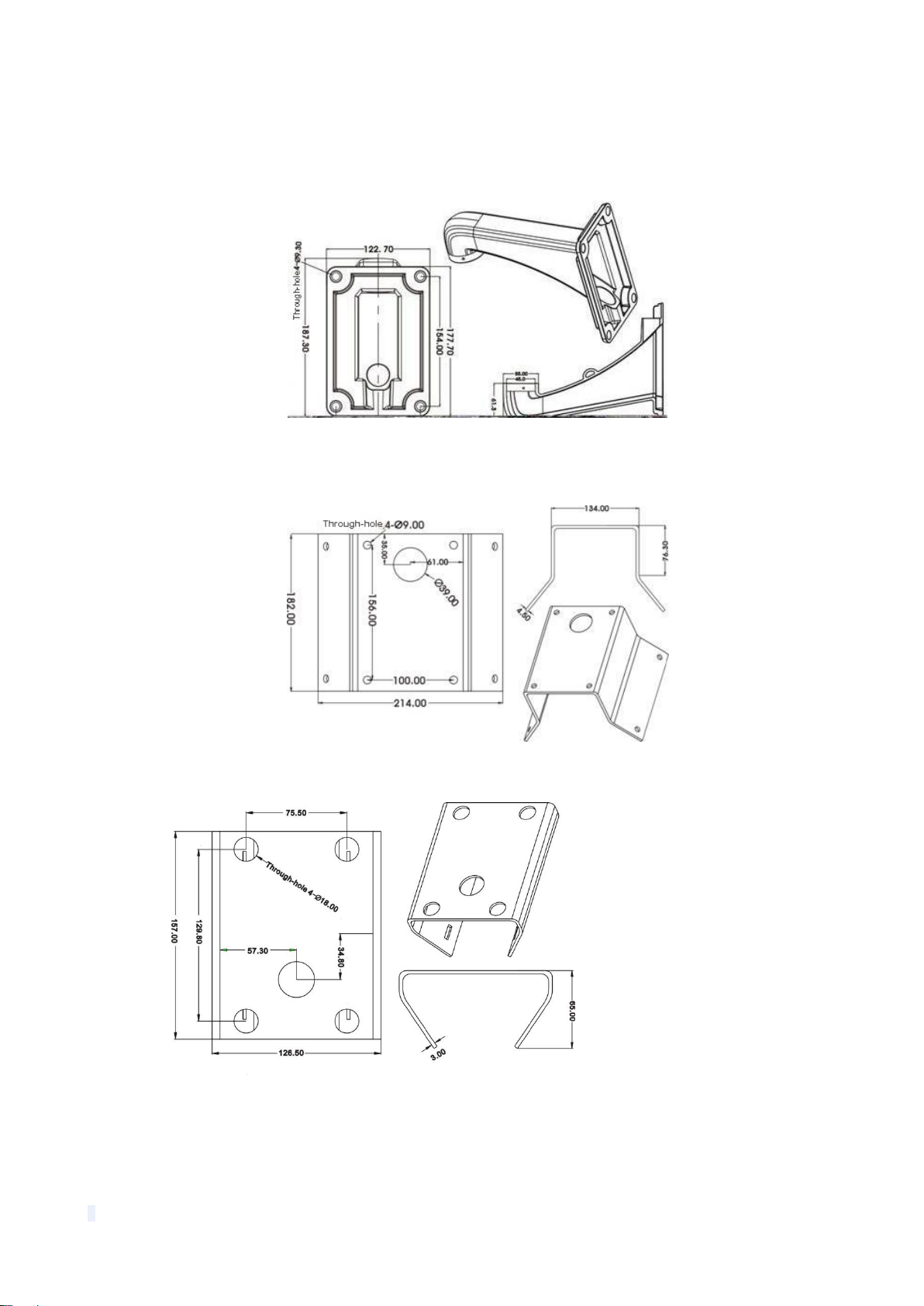
2.2 Bracket Dimensions
2.2.1 Wall Mounted Bracket
2.2.2 Corner Mounted Bracket
2.2.3 Pole Mounted Bracket
7
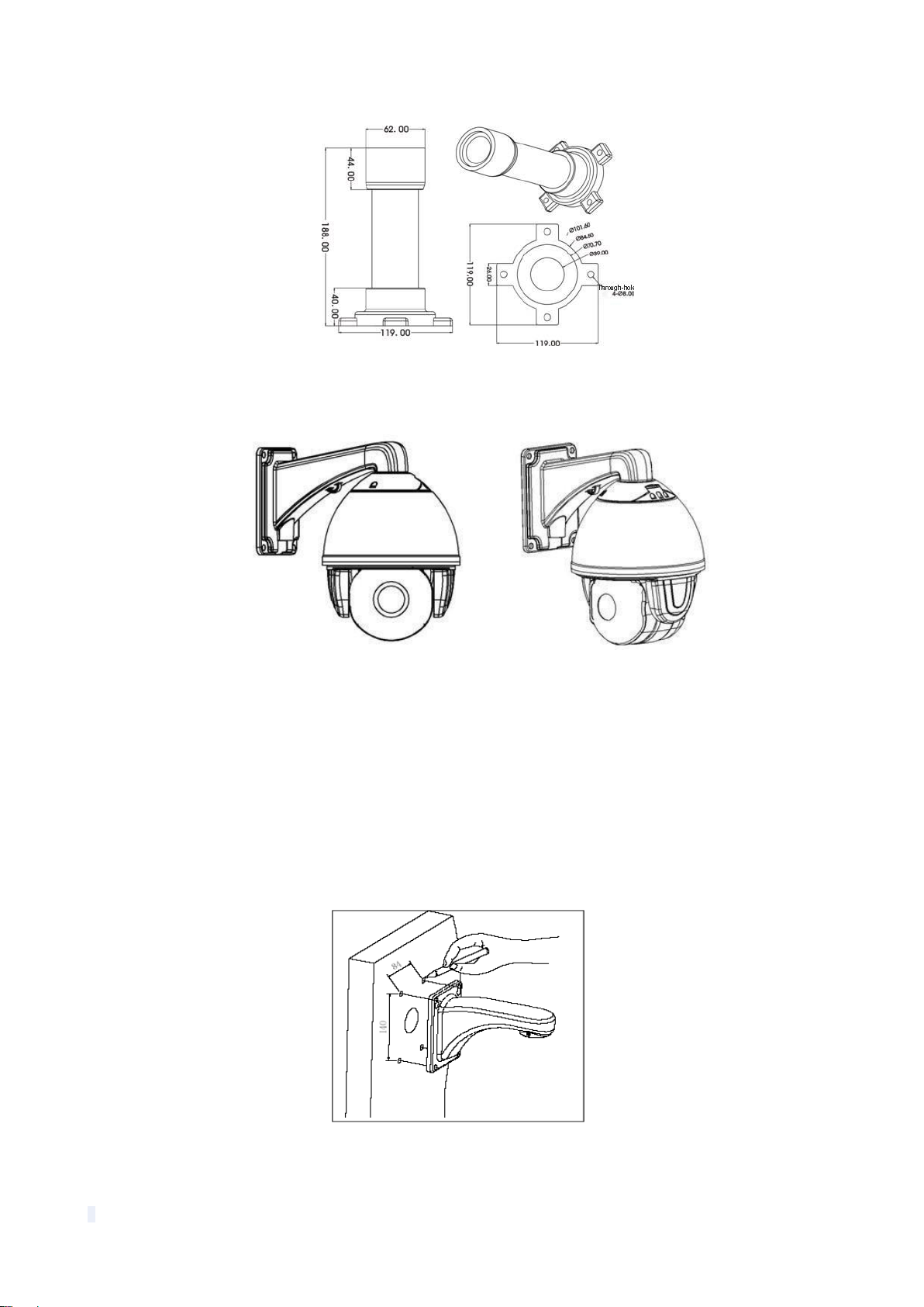
2.2.4 Ceiling Mounted
2.3 Installation of Brackets.
2.3.1 Wall Mounted
Fig 1
Installation conditions:
This wall mounted dome can be used on walls whose thickness and sturdiness should be
enough to install expansion bolt outdoors, or be used with an electrical box or mounted to a stud
indoors. The wall must be able to bear at least 4 times the weight of the dome.
To install the wall hanging bracket:
a. As shown in fig 2, use the installation holes of the wall hanging bracket as a pattern and mark
the locations of the holes on the wall.
Fig 2
b. As shown in fig 3, attach the wall hanging bracket to the wall with wire and cable passed
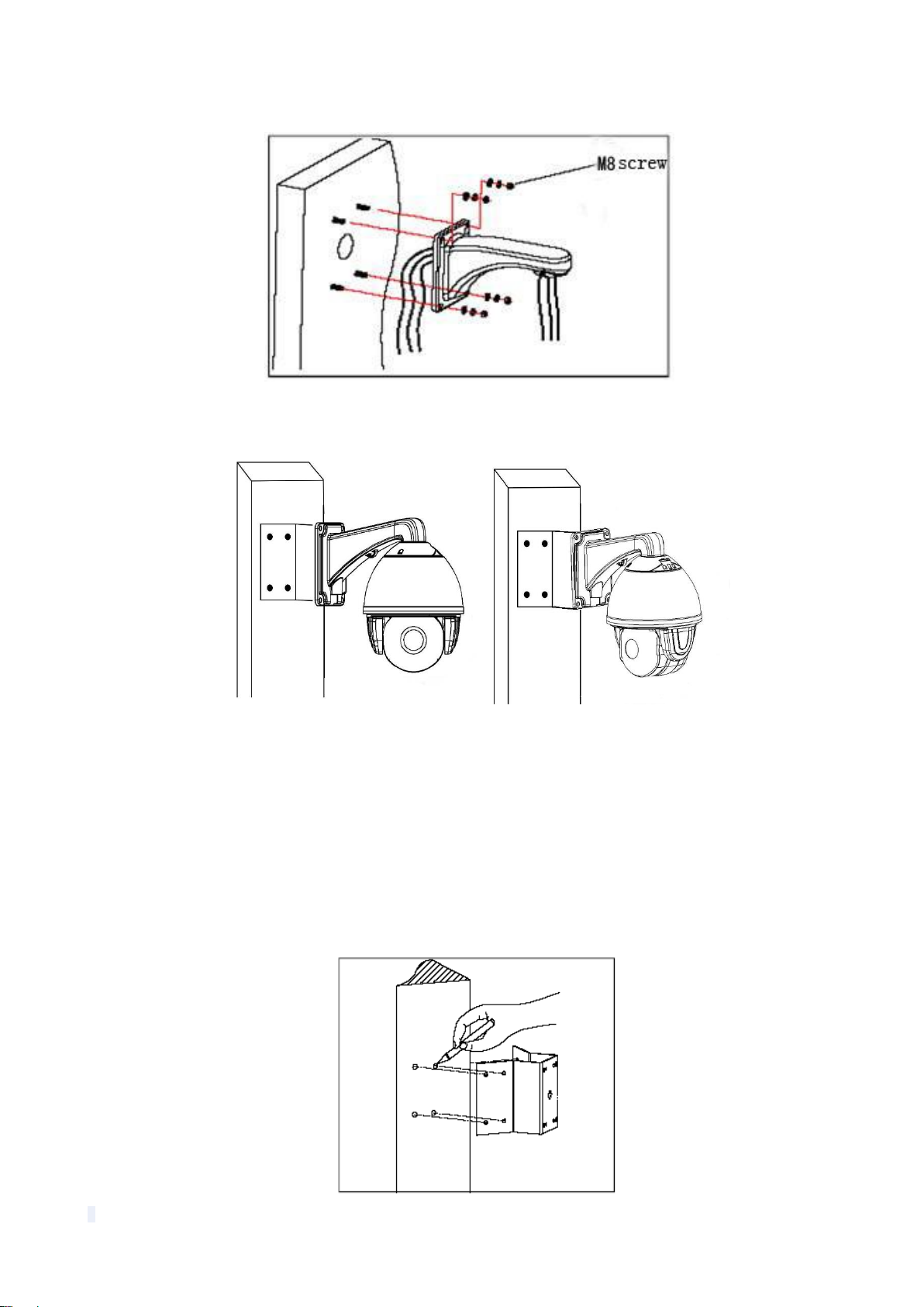
8
through it.
Fig 3
2.3.2 Corner Mounted
Fig 11
Installation conditions:
Corner mounted dome can be used in the hard wall structure with an angle of 90° whose
thickness should be enough to install expansion bolt in indoor and outdoor environment. The
wall can bear at least 4 times the weight of the dome. Install corner mounted attachment and
wall hanging bracket:
a. As shown in fig 12, with the installation holes in the corner mounted attachment as pattern,
draw punched locations on the wall with an angle of 90°and punch to install expansion bolt.

9
Fig 12
b. As shown in fig 13, use M8 screw nut to fix the base of corner mounted on the wall with all
cables through the center holes of the corner mounted, marine glue and bracket. Enough wiring
length should be left.
Fig 13
c. As shown in fig 14, fix the wall hanging bracket with all cables power through it on the corner
mounted attachment.
Fig 14
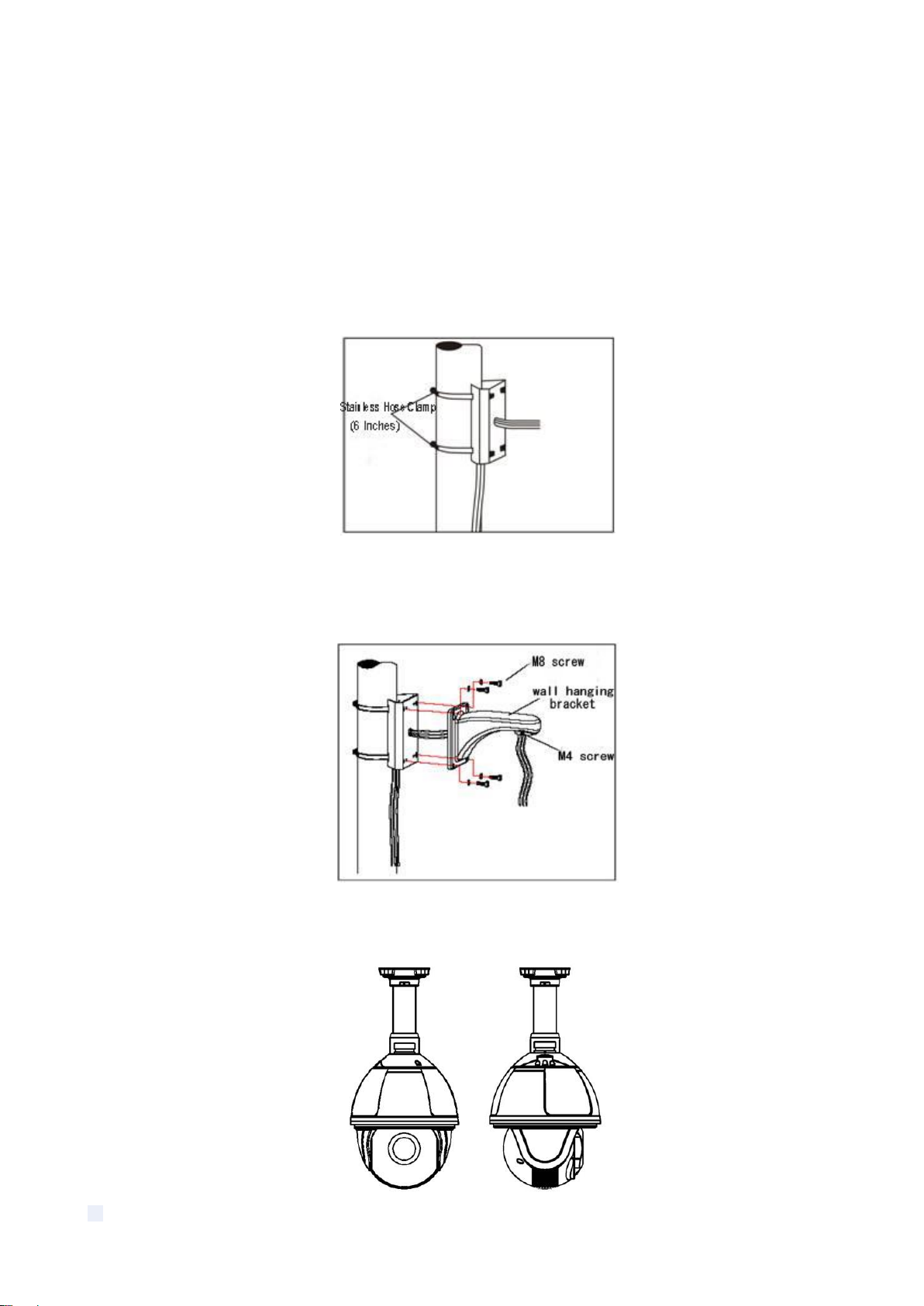
2.3.3 Pole Mounted
10
Fig 15
Installation conditions:
Pole mounted dome can be used in the hard pole structure in indoor and outdoor environment
whose diameter should match the installation size of stainless hose clamps. Factory default is 6
inches stainless hose clamps (fit φ130-152mm pillar). The pole structure can bear at least 4
times the weight of the dome. Install corner mounted attachment and wall hanging bracket:
a. As shown in fig 16, use the stainless hose clamps to fix the pole mounted attachment with all
cable through it on the pole structure.
Fig 16
b. As shown in fig 17, fix the wall hanging bracket with all cables through it on the pole mounted
attachment.
Fig 17
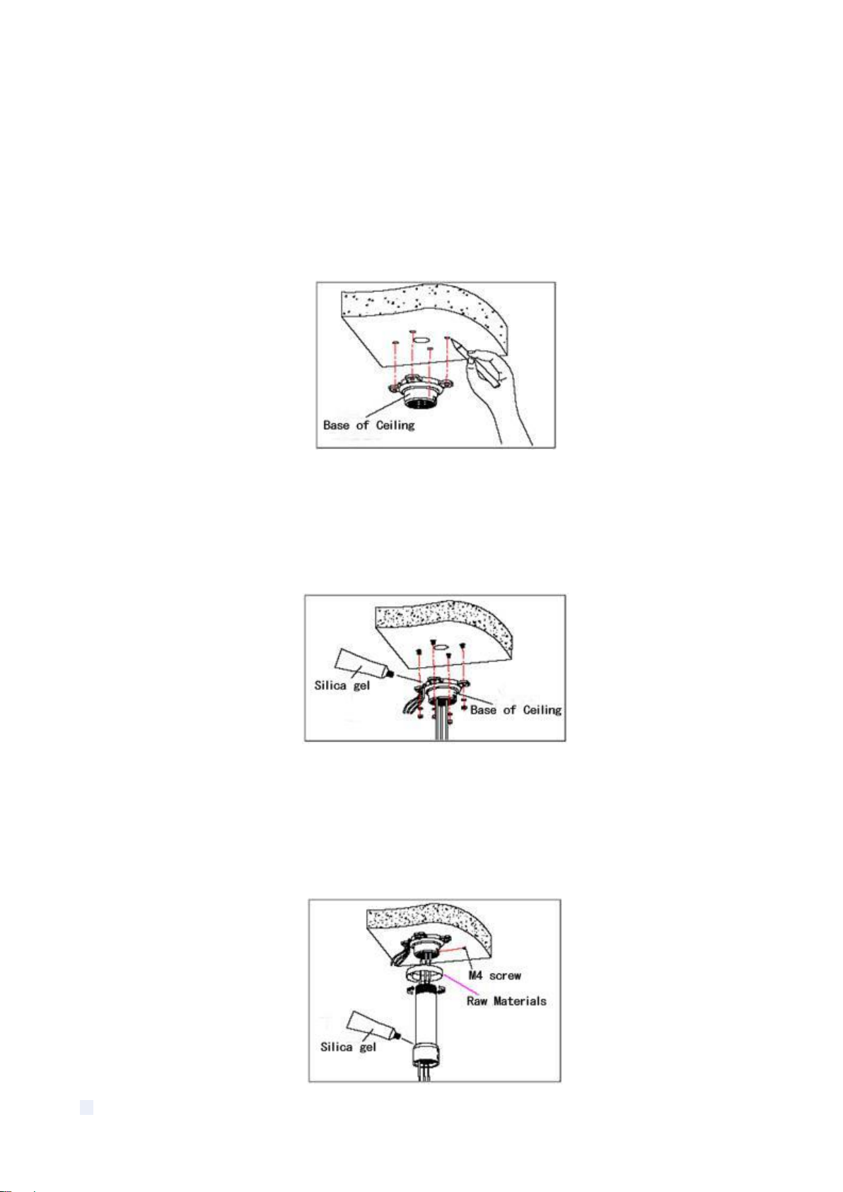
2.3.4 Ceiling Mounted
11
Fig 18
Installation conditions:
Ceiling mounted dome with thick pole can be used in the hard ceiling structure whose thickness
should be enough to install expansion bolt in indoor and outdoor environment. The ceiling can
bear at least 4 times the weight of the dome. Install the base of ceiling and boom:
a. As shown in fig 19, with the installation holes in the base of ceiling as pattern, draw punched
locations in the ceiling and punch to install M6 expansion bolt.
Fig 19
b. As shown in fig 20, at first unscrew the M4 screw at the side of the base of ceiling and split
the base of ceiling and boom. Then make the three groups of cables of power, video/control and
alarming into the side recessing seal groove of the ceiling connector bottom and through the
core hole of the base of ceiling mounted. Fix the base of hang ceiling on the ceiling board.
Fig 20
Note: If the dome is used in the outdoor conditions, use the silica gel on the faying surface of
the base of hang ceiling and the ceiling board and around the out-holes to be sure water proof
c. As shown in the fig 21, tighten the boom with electrical wire and cable through it on the base
of ceiling and screw up the M4 screw.

12
Fig 21
Note: If the dome is used in the outdoor conditions, after using enough raw materials to wrap
the thread at the upper end of boom, tighten the boom on the base of ceiling. Use the silica gel
around the joint sleeve and connector of the boom to be sure water proof
2.4 Connection
RS485 Connection
Before connecting, please turn off the power and read the instructions of all connected devices
carefully.
Fig 24

13
3. Instruction
3.1 Power On Action
When initializing the system, the operation as left figure will
run in 2 seconds.
When restoring out-of-factory settings, please wait patiently.
The operation as left figure will run in 1 minute.
This left figure means initializing the pan/tilt motor of speed
dome camera.
The initialization of pan/tilt motor completes. It is initializing
the camera and detecting the module of camera.
.
XXX is the specific model of camera module which is
displayed after camera finishes detection.
Power on self testing completes.
3.2 Basic Function
Dome Running
Control joystick or up, down, left and right key in the keyboard.
Zoom
Press ZOOM- button to make the lens farther and minify the scene.
IR SPEED DOME
PROTOCOL PELCO-D/P
COMM 2400.N.8.1
DOME ID 001
MODULE
VERSION V1.2
POWER ON
IR SPEED DOME
PROTOCOL PELCO-D/P
COMM 2400.N.8.1
DOME ID 001
MODULE
VERSION V1.2
POWER ON
IR SPEED DOME
PROTOCOL PELCO-D/P
COMM 2400.N.8.1
DOME ID 001
MODULE XXX
VERSION V1.2
POWER ON

14
Press ZOOM+ button to make the lens closer and magnify the scene.
Focus
After FOCUS- button is pressed, the object in vicinity will become clearer while the object far
away will become ambiguous.
After FOCUS+ button is pressed, the object far away will become clearer while the object in
vicinity will be ambiguous.
Iris
Press IRIS- to gradually shrink the iris and decrease the image brightness.
Press IRIS+ to enlarge the iris and increase the image brightness.
Preset Point
Setting preset, press button “preset” + ”number” + ”enter”.
Calling preset, press button “call” + ”number” + ”enter”.
Deleting preset, press button “clear” + ”number” + ”enter”.
Remark: Some preset points are used tentatively for special functions.
3.3 Special Function
The follow presets are predefined as special function, please shot+ preset No.+ enter to enable
those functions:
Note: If use some other equipments to control IR dome, some special functions probably can’t
be effective because of the limit of protocol.
PREST
FUNCTION
PRESET
FUNCTION
33
Pan scan180 º
86
BLC on
34
Reset
87
BLC off
75
Trace memory 1
88
Freeze on
76
Trace memory 2
89
Freeze off
77
Trace memory 3
91
Limited Points Scan (A-B scan)
78
Trace memory 4
92
Set left point of A-B scan
79
Digital zoom on
93
Set right point ofA-B scan
80
Digital zoom off
94
OSD menu off
81
Auto day/night
95
OSD menu on
82
Switch to night
96
Guard tour 3
83
Switch to day
97
Guard tour 2
84
Force on far light
98
Guard tour 1
85
Force on near light
99
Pan scan
Table of contents


