Skope ELITE 3D User manual
LIT 3D
SKOPE Airelec
Operating and Installation Instructions
MAN9624 Rev. 4.0 Mar. 2004 edition
Convection Panel Heaters
Vertical, Horizontal and Plinth models
2lite 3D LITV, LITH and LITPL
SKOPEAirelec Convection Panel Heaters
Introduction
SKOP Airelec heating
SKOPE Airelec Elite 3D convection panel heaters are available as
vertical, horizontal and plinthmodels, providing you with the
opportunityto choose amodel thatwill optimise the valuablewall space
available in your room. Thesedesigns havepassed rigorous testing
and quality assurance controls withboth style and safety in mind. As a
result, they have aslim profile, operatesilently, are double insulated,
include overheat protection and aresupplied with wall mounting
brackets for simple installation.
SKOPE Airelec Elite 3D convection panel heaters incorporate
electronic thermostatcontrol, andaredesignedtoaccept theEcobox2
programmable controller - whichenables master, remoteor
programmable control with real-timeoperation.
WhenpurchasingaSKOPE
product, our customers put
trustin us to deliver upon a
promise. They expect their
SKOPE heater or
refrigerator to be, amongst
other things, a totally
dependablehigh performer,
featuresthatcapture and
illustratethe key valuesthat
guide us asa company.
These values can be
summarised as durability,
reliability,safety, and
relentlessness.
Ourname, logo, andthis
product reflect our
commitment toour
customers.

3
lite 3D LITV, LITH and LITPL
SKOPE AirelecConvection Panel Heaters
Safety Information
Whenusingany electricalappliance,safety precautions should always
be observed. Read these instructions carefully,andretain forfuture
reference.
•When usedby, or near, young children or infirmpersons, close
supervisionis necessary. Youngchildren should besupervisedto
ensure that they do not play with the appliance.
•Use this appliance only with the voltagespecified on ratinglabel.
•Do NOT use this applianceother thanfor its intended use.
•Do NOT touchhotsurfaces or moving parts.
•Do NOT cover the grilles orplace any object ormaterialupagainst
the unit, as this may block entry or exhaust ofairflow.
•Do NOT probeanyopening to removefluff. To ensure trouble-free
performance it is recommended thatona regular basis the unit be
isolated from the power supply and a vacuum cleanerused to
remove dustandfluff fromtheinlet andoutletgrilles.
•Do NOT allow thesupply cordto come into contact with heated
surfaces duringoperation.
•Ifused in conjunctionwith another heater fittedwith theEcobox2
electronic controller,ensure that the heater can operatesafely in
accordance with these operational instructions.
•Regulations require thatelectrical work be carriedout by
authorised persons. Foryour ownsafety and that ofothers, ensure
this is done.
•Ifthesupply cordbecomes damaged, it mustbe replaced by a
SKOPE authorised service agent, or similarly qualified person, in
order to avoida hazard.
•For service, contact your nearest authorised service agent.
Caution:
Iftheheater is used onFreeze Guard setting, or operatedvia atimer,
ensure theheater is not obstructed in any way by furnitureor drapes
etc. Ensure the heater canoperatesafely, shouldtheheater switchon
when the ambienttemperaturedrops, or a timer activates the heater.

4lite 3D LITV, LITH and LITPL
SKOPEAirelec Convection Panel Heaters
Safety Cutout
Your SKOPE Airelec convection heater is fittedwith anauto-reset
thermal cutout. This safety device will automatically switch off the
elements shouldtheheater reach an abnormal temperature.
Should this occur: switchoffthe heater immediately, and disconnect
fromthepower supply. Allow theheater tocool down, and check for
blockageofthe air vents. Useavacuum cleanertoclean if necessary.
Ifthe heater still fails to operate, contact your nearestauthorised
service agent.
NOTE: Theheaterindicator neonmaystill beon. Check thatthere is no
heat being emitted from the grilles.
Care
Theheater is best wipeddown, fromtime totime, witha dampcloth.
Donotuse anyabrasive cleaners.
5
lite 3D LITV, LITH and LITPL
SKOPE AirelecConvection Panel Heaters
Control Settings
Freeze Guard
TheFreeze Guardsetting, on the selector switch,is usedto provide
heat if theambienttemperaturedropstoalevel close to freezing.This
settingis usefulduring extendedperiods ofabsence, or for unoccupied
rooms. The thermostat knob does not need to be adjusted for Freeze
Guardto operate.
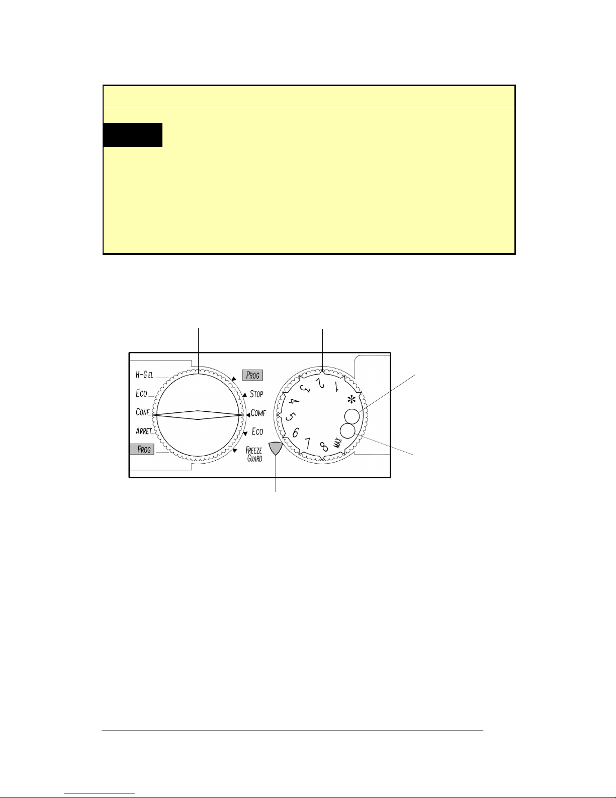
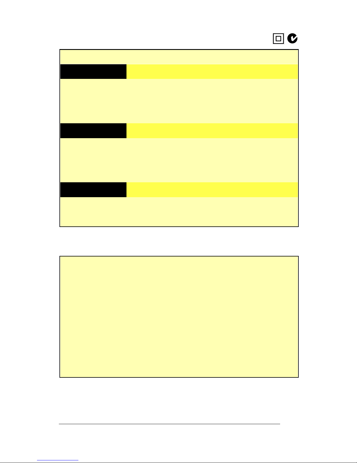
OP RATION
PROG
Required for use with the Ecobox2
programable controller. IfEcobox2 is not used,
this settingwill be identical to COMF
STOP OFF
COMF Thermostat setting
ECO 3°C to 5°C lower than thermostat setting
FREEZE GUARD Approx.7°C (for frost protection)
Table1: Control Settings
Figure 1: Control Panel
Minimum setting
plastic cap
Maximum setting
plastic cap
Selector switchThermostatknob
Neon indicator
PROG

6lite 3D LITV, LITH and LITPL
SKOPEAirelec Convection Panel Heaters
Installation
This appliance must beinstalled in accordance with the relevantelec-
trical wiringrules and regulations. Theheater must notbe located
immediately below asocket-outlet. A suitable disconnection device
(acting inall active supplies) is requiredto be incorporatedin the fixed
supply wiring.Whenused in a bathroom, the heater must be installed
such that the controls cannot be touched by a personinthebath or
shower.
Due totheprecision ofthe heater’s electronic thermostat, the unitis
highly sensitive toair drafts. For this reason,carefully determine the
unit’s locationbefore installation.
Theminimumrequireddistance from theheater to any floor is 150mm.
Theminimum requireddistancefromthe heatertoany adjacent wall is
200mm (see figure3 onpage 9).
Connection Details
Theheater is suppliedwith a1.8m 2-coreflex andplug.For singleoper-
ationtheheater can be pluggeddirectly into asocket outlet.
NOTE: This double insulated (Class II) appliance does NOT require
Earthing.
Pilot wire
For pilot wire operation orpermanent connectionto fixed wiring, the
plugmust beremoved. If thepilotwireis tobe used, it must beconnect-
ed to a separate pilot wire circuit. The black pilot wire MUST NOT be
connectedtoEarth.Ensure thepower supply tothe pilot wire, as well
asthemains power to the heater, is disconnected before any servicing
or maintenance is carried out.
Whenpermanently wired, andthepilot wire is notbeing used, thepilot
wire mustbe connectedto a potential freeterminal ina switched
permanent connection unit.
NOTE: Forpilot wire connection details, seeseparate‘Ecobox2Pilot
Wire Transmitter’ Operating Instructions (P/No: MAN9762).

7
lite 3D LITV, LITH and LITPL
SKOPE AirelecConvection Panel Heaters
Mounting Instructions
Theheater is fixed on the wall with the mountingbracket attached to
back of theheater.
To secure mounting bracket to the wall
1.Removethewall mounting bracket from the back ofthe heater,
by compressingthebayonetfittings atthetopand/or sides ofthe
bracket, which clip into the heater body (see figure 2 below).
2.Place themountingbracket against thewall, ensuringthe bracket
is level and the minimum distance between the heater andthe
adjacent surfaces are adheredto (see table 2on page8).
3.Mark anddrill the fixing holes at thetopandbottom of the
mounting bracket,andattached to the wall withsuitable screws
and/or wall anchors (see figure 3onpage 9).
4.Locatetheheater over the bottomclipsof the wall bracket and
thenpush the heater securely into the bayonet fittings on the top
and/or sides of thebracket.
To remove heater from the wall
1.By using a pointedtip screwdriver, pushinandlever out the
bayonet fittings at the top and/or sides of wall mounting bracket.
2.Lift theheater upandaway from the wall.
Figure2: Wall Mounting Bracket Fitting
Bayonet
fitting
Push IN
Wall mounting bracket removed from heater
Wall mounting bracket
Lever OUT
Heater bodyHeater body

8lite 3D LITV, LITH and LITPL
SKOPEAirelec Convection Panel Heaters
Installation
Read the following dimensions inconjunction with figure 3 on page 9.
Important!
When operated for the first time, the heater may emit a
small amount of smoke. This is normal, and should clear
within a few minutes. It is recommended you open
windows and doors during this process.
MOD LS DIMNSIONS
Vertical models A B C D
ELITV.ETP10 154mm 200mm 115mm 91mm
ELITV.ETP15 178mm 200mm 120mm 222mm
ELITV.ETP20 320mm 200mm 140mm 220mm
Horizontal models A B C D
ELITH.ETP10 234mm 200mm 112mm 94mm
ELITH.ETP15 248mm 200mm 138mm 214mm
ELITH.ETP20 405mm 200mm 221mm 214mm
Plinth models A B C D
ELITHPL.ETP10 595mm 200mm 90mm 235mm
ELITHPL.ETP12 755mm 200mm 90mm 235mm
SKOPE Industries Limited reserve theright to alter specifications without notice.
Table2: Installation Dimensions

9
lite 3D LITV, LITH and LITPL
SKOPE AirelecConvection Panel Heaters
Wall Mounting Bracket
Read the following diagram in conjunctionwith table2 on page 8.
NOTE: The wall mounting bracketon models ELITV.ETP10 and
ELITH.ETP10 differs tothediagrambelow, in that they use only one
vertical fixingbracket.
CD
B
200
mm
A
150 mm
Wall
Mounting bracket
Bottom clips
Heater outline
IMPORTANT
Minimum
IMPORTANT Minimum Floor level
Bayonet fittings
Top fixing holes
Bottom fixing holes
Side fixing hole
(ETP10 models only)
Figure 3: Wall Mounting Bracket

10 lite 3D LITV, LITH and LITPL
SKOPEAirelec Convection Panel Heaters
Limiting the Thermostat
Thethermostat knob can be adjusted soas to limit the maximum and
minimum temperatures, or locked ata fixed temperature position.
Limiting to a maximum temperature
1.Removethermostat knob fromtheheater control panel.
2.Removethemaximumsetting plastic capfromthe knob (shown
in figure 1 on page 5).
3.Replace the thermostatknob.
4.Turn and place the knobat the maximum setting required.
5.Fasten asmall screw (e.g.No.4x 1/4” self-tapper) in the hole.
The screw should be small enough not to impede movement of
the knob up to the maximum limit.
6.Returnthe knob tothe* position.
7.The knob should turn freely, upto the maximum setting.
Limiting to a maximum and minimum temperature
1.Seta maximum temperature asabove.
2.Removetheminimumsetting plastic capfromtheknob (shown in
figure 1 on page5).
3.Turn and place the knobat the minimum settingrequired.
4.Fasten asmall screw (e.g.No.4x 1/4” self-tapper) in the hole.
The screw should be small enough not to impede movement of
the knob between the twolimits.
5.The thermostat knob should turnfreely between the two limits.
Locking the thermostat knob
1.Removethermostat knob fromtheheater control panel.
2.Removeeither one of theplastic caps fromtheknob.
3.Turn and place the thermostat knob at the requiredsetting.
4.Fasten ascrew (e.g. No.6 x 1/4” self tapper) into thehole.
The screw should be large enough to impede movement of the
knob.
5.The thermostat knob should now belockedat the required
setting.
11
lite 3D LITV, LITH and LITPL
SKOPE AirelecConvection Panel Heaters
Specifications
MOD LS Wattage Height Width Depth
Vertical
ELITV.ETP10 900-1000 W 650mm 360mm 105mm
ELITV.ETP15 1400-1500 W 650mm 520mm 105mm
ELITV.ETP20 1800-2000 W 650mm 680mm 105mm
Horizontal
ELITH.ETP10 900-1000 W 400mm 440mm 105mm
ELITH.ETP15 1400-1500 W 400mm 600mm 105mm
ELITH.ETP20 1800-2000 W 400mm 840mm 105mm
Plinth
ELITHPL.ETP10 900-1000 W 245mm 920mm 105mm
ELITHPL.ETP12 1150-1250 W 245mm 1080mm 105mm
Table3: HeaterDimensions
L CTRICAL
Supply: 230-240 Volts a.c. 50Hz, single phase
Wiring: 1.8 metre flex and plug(2-coreplus pilotwire),
withthefollowingpolarity:
Phase= Brown
Neutral = Blue
Pilotwire = Black *
* Theblack pilot wire MUST NOT beconnected
to Earth. Seepage 6for connection details.
Double Insulated
Table 4: Electrical Specifications

12 lite 3D LITV, LITH and LITPL
SKOPEAirelec Convection Panel Heaters
Contact Addresses
Servicing
Ifyour heater is in needof servicing, contact your nearest authorised
service agent(seeseparate enclosed list of service agents).
New Zealand
SKOPE INDUSTRIES LIMITED
PO Box 1091, Christchurch
New Zealand
Freephone: 0800 947 5673
Fax: (03) 983 3896
Email: [email protected]
Website: www.skope.co.nz
Australia
SKOPE AUSTRALIAPTY LTD
A.C.N. 000 384 270
PO Box 7543, Baulkham Hills B.C.
NSW 2153, Australia
Freephone: 1800 121 535
Freefax:1800 121 533
Email: [email protected]
Website: www.skope.com.au
This manual suits for next models
9
Table of contents
Other Skope Heater manuals


Popular Heater manuals by other brands

Opal
Opal E176004 instruction manual

Chromalox
Chromalox CAF-20215 Installation, operation and maintenance

Detroit Radiant Products
Detroit Radiant Products DSCS-9 Series Installation, operation, maintenance and parts manual

Bellus
Bellus PTC15 manual

S&P
S&P 3MCN User instructions

GUTFELS
GUTFELS Smart Cube instruction manual


