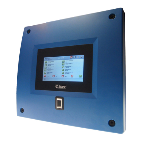
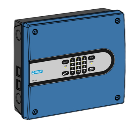
Skov DOL 2200 Manual

DOL 2200 Alarm System
Technical User Guide

Technical User Guide
DOL 2200 Alarm System
Program Version
The product described in this manual holds software. This manual corresponds to:
•Software version 2.03
It was released in 2014.
Product and Documentation Revision
SKOV A/S reserve the right to change this document and the product herein described without further
notice. In case of doubt, please contact SKOV A/S.
Latest date of change appears from the back of this manual.
In case of maloperation or improper use, alarm systems can result in production loss or
cause loss of lives among animals.
SKOV A/S recommend that alarm systems should be mounted, operated and serviced only
by trained staff and that an emergency opening system and an alarm system be installed as
well as maintained and tested at regular intervals, according to SKOV A/S’s terms of sale
and delivery.
A certified electrician must carry out the installation in accordance with applicable
national rules and in Europe in accordance with applicable EU rules.
Do not use pre-paid service phone cards in connection with DOL 2200 GSM.
Note
•All rights reserved. No part of this manual may be reproduced in any manner whatsoever
without the express written permission from SKOV A/S.
•SKOV A/S have made reasonable efforts to ensure the accuracy of the information contained
in this manual. Should any mistakes or imprecise information occur in spite of this, SKOV
A/S would appreciate being notified thereof.
•Irrespective of the above, SKOV A/S shall not accept any liability with regard to loss or
damage caused or alleged to be caused by reliance on any information contained herein.
•Copyright 2014 by SKOV A/S.

Technical User Guide 3
DOL 2200 Alarm System
1PRODUCT DESCRIPTION 5
2USER’S GUIDE 5
2.1 Get started ................................................................................................... 5
2.1.1 Selecting a Menu, right Adjustment Knob..................................................................... 5
2.1.2 Selecting a Line, left Adjustment Knob.......................................................................... 5
2.2 DOL 2200 Temperature Alarms........................................................................ 6
2.3 Alarm Handling ......................................................................................... 6
2.3.1 Stop Alarm at DOL 2200.................................................................................................. 6
2.3.2 Stop Alarm over the Phone.............................................................................................. 6
2.3.3 Stop Alarm –Acknowledge via Phone............................................................................ 6
2.3.4 Stop Alarm via SMS (GSM only).................................................................................... 6
2.4 Testing the Alarm System ................................................................................ 7
2.4.1 Display info about the system status ............................................................................... 8
2.4.2 Display information about the status of inputs.............................................................. 9
2.5 Outline of DOL 2200 menus.............................................................................10
2.5.1 MAIN - Main menu ........................................................................................................ 11
2.5.2 MAX - Maximum temperature ..................................................................................... 11
2.5.3 MIN - Minimum temperature ....................................................................................... 11
2.5.4 REL+ - Maximum relative temperature....................................................................... 12
2.5.5 REL- - Minimum relative temperature ....................................................................... 14
2.5.6 NORMAL –Normal temperature................................................................................. 14
2.5.7 AUX –Summer rise........................................................................................................ 15
2.5.8 CAL - Calibration........................................................................................................... 15
2.5.9 TIME –Test, the clock, date and year.......................................................................... 16
2.5.10 INST –Selection of alarm type...................................................................................... 19
2.5.11 TEL –Telephone numbers, SMS-alarm, setting the speech computer...................... 23
2.6 Log Function ....................................................................................................26
2.6.1 Graphical Log ................................................................................................................. 26
2.6.1.1 Graphic Display of Temperature Course.......................................................................... 26
2.6.1.2 Operation at graphic display............................................................................................. 26
2.6.2 Event Log......................................................................................................................... 27
2.7 Speech Computer ............................................................................................28
2.7.1 Access to Operation through locally connected Telephone......................................... 28
2.7.2 Access to Operation through externally connected Telephone................................... 28
2.7.2.1 Recording of User Name and Words................................................................................ 28
2.8 Remote Control via Telephone (special Functions).......................................29
2.8.1 Entering........................................................................................................................... 29
2.8.1.1 Entering of Telephone Numbers via Telephone............................................................... 29
2.8.1.2 Changing name of input.................................................................................................... 29
2.8.1.3 Changing Code ................................................................................................................. 29
2.8.1.4 Setting of auto answer....................................................................................................... 29
2.8.1.5 Dial-up Pattern.................................................................................................................. 29

4Technical User Guide
DOL 2200 Alarm System
2.8.1.6 Varying Manning on Duty................................................................................................ 30
2.8.1.7 GSM Signal ...................................................................................................................... 30
2.8.1.8 Glossary for Changing Name of Input.............................................................................. 31
2.8.2 Checking the Entries ...................................................................................................... 32
2.8.3 Deletion............................................................................................................................ 32
2.8.4 Service break................................................................................................................... 32
2.9 Enquiries and Remote Control via Phone or SMS.........................................33
2.9.1 Start/stop and Restart of Inputs via Phone/SMS after Alarm Occurrence............... 34
2.9.2 Register Numbers ........................................................................................................... 34
2.9.3 Interaction with Fax or Modem..................................................................................... 34
2.9.3.1 Speech Computer answers before Fax/Modem ................................................................ 34
2.9.4 Error Messages from Speech Computer in loudspeaker ............................................ 35
2.10 Remote Control via SMS..................................................................................35
3INSTALLATION GUIDE 36
3.1 Electric Connection..........................................................................................36
3.2 Dimensioning of Cables ..................................................................................37
3.3 Wiring Diagram.................................................................................................37
3.3.1 Wiring diagram –common Conductor for Temperature Sensors............................. 39
3.4 Starting .............................................................................................................40
3.4.1 DIPSWITCH on Computer Board in the Cover.......................................................... 41
3.4.1.1 Automatic Test of Battery................................................................................................. 41
3.4.2 System with several DOL 2200...................................................................................... 41
3.4.2.1 Extension Module or Basic Module ................................................................................. 41
3.4.2.2 System Station Number.................................................................................................... 41
3.4.2.3 Setting of dipswitch for system with several DOL 2200.................................................. 43
3.4.2.4 Error diagnosis on the RS485 network............................................................................. 43
4MAINTENANCE INSTRUCTIONS 44
4.1 Testing..............................................................................................................44
4.2 Cleaning............................................................................................................44
4.3 Start/stop all Monitoring..................................................................................44
4.4 Removal for Recycling/Disposal.....................................................................45
5TECHNICAL DATA 45
6AUXILIARY SCHEME FOR ACCOMPLISHED TEST 46

Technical User Guide 5
DOL 2200 Alarm System
Selecting a
menu
Changing a value
Activate and deactivate
Selecting a line
Next:
- page in menu
- letter
- digit
Menu page
1
1 Product Description
This manual mentions operation, installation and starting up the DOL 2200 alarm system. The main
section of the manual User’s guide describes the fundamental knowledge necessary to operate the
system based on a setup with one alarm system. Read the manual before starting to use the alarm
system.
DOL 2200 alarm system is primarily used for monitoring ventilation in livestock houses and can
monitor the temperature in up to ten sections. As an alternative, the system can be used to trigger
alarms for empty silo, blocked augers, oil burner defects etc.
The alarm unit can be set to alarm by means of phone, beep, flash and alarm (horn/siren).
2 USER’S GUIDE
2.1 Get started
2.1.1 Selecting a Menu, right Adjustment Knob
DOL 2200 holds 11 menus (described in paragraph 2.5).
•Turn the adjustment knob to select a menu
•Press to view the submenus
(page number appears in the bottom right-hand corner
of the display)
2.1.2 Selecting a Line, left Adjustment Knob
The left adjustment knob is used to select a menu line.
When the menu line has been selected, changes can be carried out
using and . .
activate or deactivate a function
SYS Reading the system state (top menu line)
OUT Reading the outside temperature (bottom menu line)

6Technical User Guide
DOL 2200 Alarm System
2.2 DOL 2200 Temperature Alarms
DOL 2200 holds two types of temperature alarms: absolute and relative ones.
Alarm type
Name
Setting
Alarm
Absolute temperature alarm
Maximum temperature
32 °C
Alarm at 32 °C
Minimum temperature
14 °C
Alarm at 14 °C
Relative temperature alarm
Maximum relative temp.
5 °C
Alarm at Normal temp. + 5 °C
Minimum relative temp.
-4 °C
Alarm at Normal temp. -4 °C
NB Normal temp. is an average of the temperature in the house from 6:00-7:00.
See paragraph 2.5.1 and 2.5.2 for a survey of all alarms in DOL 2200.
2.3 Alarm Handling
2.3.1 Stop Alarm at DOL 2200
1) Press to acknowledge the alarm, switch off the siren and terminate the telephone call.
DOL 2200 does not trigger an alarm again for this error until it is restarted. Continue with
point 2-4 now or later.
2) Select MAIN using the right adjustment knob: read the cause for the alarm.
3) Remedy the cause for the alarm.
4) Press to restart the alarm monitoring for this error. STATE displays “OK”.
2.3.2 Stop Alarm over the Phone
1) Press the # button on the phone to acknowledge the alarm. Or as in paragraph 2.3.1 (on site).
Please note that some telecom companies use the "#" key as a command. This can disconnect DOL
2200’s message so that it cannot be heard. You can set which key you want to use to acknowledge
telephone calls (see section 2.5.11, TEL, menu page 3).
DOL 2200 can be set to repeat alarm calls to a telephone until acknowledgement is also carried out on
the actual DOL unit (see TIME section, menu page 3).
2.3.3 Stop Alarm –Acknowledge via Phone
If you know that an alarm has been generated –for example via an SMS or you have heard the siren –
you can call the alarm system (see the manual, section 2.7.2).
1) Call the number to which the alarm system is connected.
2) When the password has been entered, DOL 2200 says: “Password accepted”; the alarms are
acknowledged and the siren and additional calls stop.
3) Remedy the cause of the alarm.
4) Press to restart the alarm monitoring function. STATUS now shows 'OK'.
2.3.4 Stop Alarm via SMS (GSM only)
If the voice computer is set up to SMS alarm, an SMS is sent to the first telephone number on the list
under SMS activation. Also see paragraph 2.5.11.
Answer the SMS alarm and send DOL 2200’s password ending with a point; e.g. '1.' (1 is the
factory-set password).
DOL 2200 will acknowledge the alarm and send an SMS text to all phone numbers indicating
that the alarm has been acknowledged, the alarm type and the phone no. that acknowledged.

Technical User Guide 7
DOL 2200 Alarm System
2.4 Testing the Alarm System
1) Select the input you wish to test.
2) See in the menu INST which alarm signal is activated by the input (for instance horn+dialup,
see paragraph 2.5.10).
3) Trigger the alarm:
•If it is an input with temperature sensor –it is warmed up by warm water
•If it is an ON/OFF controlled input –the function is activated
4) Check that the alarm is activated as expected (horn+dial-up, only horn, beep etc.).
5) Check that the phone call is made to the encoded numbers (in the menu TEL, see paragraph
2.5.11).
6) Stop the alarm (press on the alarm unit. Press the # button if done over the phone).
Please note that some telecom companies use the "#" key as a command. This can disconnect
DOL 2200’s message so that it cannot be heard. You can set which key you want to use to
acknowledge telephone calls (see section 2.5.11, TEL, menu page 3).
7) Sign for accomplished test in the scheme at the back of this manual (see section 6).
As a minimum, the alarm system must be tested according to the requirements of your
insurance company.
SKOV A/S recommend that you test the alarm system every week.
See paragraph 4.1 for further testing.

8Technical User Guide
DOL 2200 Alarm System
2.4.1 Display info about the system status
System state: ALARM
The top line shows the system status.
The bottom line amplifies the status.
STATE
Input 1
Input 2
Input 3
Input 4
Input 5
Input 6
Input 7
Input 8
21.8°
21.5°
21.2°
21.1°
21.8°
21.5°
21.8°
21.3°
OK
OK
OK
OK
OK
OK
OK
OK
Input 9
15.8°
MIN
Input10
Outdoor
21.8°
12.0°
OK
OK
Alarm on input
Status text
Text bottom line
Supplementary explanation
OK
System OK
There is no alarm.
ALARM
Alarm on input
There is alarm at one or more inputs (regarding input
status, see below sketch).
EXTRN
Alarm From Extrn
Unit
There is alarm in another unit, e.g. another DOL 2200 panel
or the speech computer.
BREAK
Service break
Monitoring of the inputs has temporarily been switched off.
The break lapses by itself or can be disconnected in the
menu SYS+TEL. Press .
-
Supervision
suspended
Monitoring of the DOL 2200 has been deactivated (in the
menu SYS+MAIN).
WARN
Battery is not OK
Less than 11.7 V was measured during the battery test.
Soft alarm. Change the battery as soon as possible.
BATT
Faulty battery
Less than 11.5 V was measured during the battery test (see
section 3.4.1.1). Battery fails during test. Change the
battery NOW.
LOBAT
Low battery voltage
There is no mains voltage and the battery voltage is
critically low (see section 3.4.1.1). This is the last warning.
DOL 2200 can no longer safeguard the monitoring of the
inputs.
230V
Power failure
230 volt lacking. DOL 2200 is now working by means of the
battery.
POWER
Power monitor relay
Main power monitoring relay input is cut out or short-
circuited (Normal = 150Ω).
COM
Error:Speech
processor
When dipswitch 5 is ON, the front panel of DOL 2200
monitors the connection to the speech computer.
The error can occur in two situations:
1. DOL 2200 has not been scanned ((Set the right-hand
rotary button to TEL and the left one to the 7. Press
for two seconds).
2. DOL 2200 has lost connection with the speech computer
and an alarm call cannot be expected.

Technical User Guide 9
DOL 2200 Alarm System
2.4.2 Display information about the status of inputs
System state: ALARM
The right column shows the status of an input.
The bottom line shows the status of the selected input.
STATE
Input 1
Input 2
Input 3
Input 4
Input 5
Input 6
Input 7
Input 8
21.8°
21.5°
21.2°
21.1°
21.8°
21.5°
21.8°
21.3°
OK
OK
OK
OK
OK
OK
OK
OK
Input 9
15.8°
MIN
Input 10
Outdoor
21.8°
12.0°
OK
OK
Temp. too low, MIN
Info
Info in display
Supplementary explanation
-
Supervision suspended
Monitoring of the input has been deactivated (in the menu
MAIN). The text is flashing.
OK
State OK
There is no alarm.
MIN
Temp. too low, MIN
Inside temperature is below Minimum temperature (in the
menu MIN).
MAX
Temp. too high, MAX
Inside temperature is exceeding Maximum temperature
(in the menu MAX).
RISE
Summer rise
Alarm limit for MAX and/or REL+ has been raised due to
high outside temperature. Summer rise can be adjusted
in the menu AUX.
SHORT
Short circuit cable
There is a short circuit on the cable to an ON/OFF input
with monitored line or to a temperature sensor. Possibly
water inside the sensor or moisture in the cable/splice.
CABLE
Broken cable
The cable is disconnected.
ERROR
Error by input
Alarm from the ON/OFF-input.
REL-
Temp. too low, REL-
Inside temperature is below Normal temperature - the
number of degrees which REL- has been set to.
REL+
Temp. too high, REL+
Inside temperature is exceeding Normal temperature -
the number of degrees which REL+ has been set to.
See also paragraph 2.9.4 Error Messages from Speech Computer in loudspeaker.

10 Technical User Guide
DOL 2200 Alarm System
2.5 Outline of DOL 2200 menus
The scheme is an outline of DOL 2200 menus. Below each menu is
described in details. If necessary, read these sections first.
MAIN
Main menu: current temperatures and status for each input and for the system (alarm/no alarm)
MAX
Maximum temperature
MIN
Minimum temperature
REL+
Maximum relative temperature
REL-
Minimum relative temperature
NORMAL
Normal temperature (average at 06-07)
AUX
Summer rise (impact of the outside temperature)
CAL
Adjustment of temperature sensors (entry of calibration value for temperature sensors)
TIME
Menu page 1
Time, date and year
Test: horn, call, function og system
Menu page 2
Various time indications and setting of the display
Menu page 3
Keyboard and test setting
Menu page 4
Technical info
INST
Menu page 1
Alarm activates: horn+dial-up, soft, only horn, etc.
Menu page 2
Input type: Temperature / ON/OFF / Ω ON/OFF
Menu page 3
Station number
Menu page 4
Naming of inputs
Menu page 5
Input number
Menu page 6
Input user name
Menu page 7
Acknowledge time
Menu page 8
Auto restart of alarms
TEL
Menu page 1
Service break, Phone numbers, Scanning stations, Test call, Activate local
phone
Menu page 2
SMS alarm
Menu page 3
Delay dial-up, Auto answer, Dial the same number, Word number at alarm,
Start dial number
Menu page 4
Register speech, Unit speech (e.g. °C), Alarm speech, Line monitoring, Dial
tone test
Press to view the submenus. When the last menu page is displayed –e.g. page 3, the display
returns to menu page 1 by pressing .

Technical User Guide 11
DOL 2200 Alarm System
2.5.1 MAIN - Main menu
MAIN In the main menu, status and current values for all ten inputs as well as outside
temperature are displayed.
System state: OK
The column to the right shows the alarm status of the inputs.
The bottom line shows the alarm status of the selected input.
You can stop the monitoring of an input.
Select the input and press .
You can eliminate the input if it is not going to be used.
Select the input and press for 2 sec.
If the input is to be used later, press again for 2 sec.
STATE
Input 1
Input 2
Input 3
Input 4
Input 5
Input 6
Input 7
Input 8
Input 9
Input
Outdoor
23.8°
24.5°
0.0°
0.0°
0.0°
0.0°
0.0°
0.0°
0.0°
0.0°
24.2°
-
-
-
-
-
-
-
-
-
-
OK
State OK
If the Outdoor input is removed, it is not possible to activate Summer rise (REL+ menu).
2.5.2 MAX - Maximum temperature
MAX There will be an alarm when the inside temperature exceeds Maximum temperature.
The function is found in a SKOV climate computer as alarm for
Absolute high temperature.
In addition, you can set a maximum temperature for Outdoor
under MAX, so DOL 2200 generates an alarm when the outside
temperature exceeds this temperature.
MAXIMUM TEMPERATURE
Input 1
Input 2
Input 3
Input 4
Input 5
Input 6
Input 7
Input 8
Input 9
Input
Outdoor
32.0°
32.0°
32.0°
32.0°
32.0°
32.0°
32.0°
32.0°
32.0°
32.0°
40.0°
2.5.3 MIN - Minimum temperature
MIN There will be an alarm when the inside temperature is below Minimum temperature.
In addition, you can set a minimum temperature for Outdoor under
MIN, so DOL 2200 generates an alarm when the outside
temperature is below this temperature.
MINIMUM TEMPERATURE
Input 1
Input 2
Input 3
Input 4
Input 5
Input 6
Input 7
Input 8
Input 9
Input
Outdoor
14.0°
14.0°
14.0°
14.0°
14.0°
14.0°
14.0°
14.0°
14.0°
14.0°
-1.0°

12 Technical User Guide
DOL 2200 Alarm System
2.5.4 REL+ - Maximum relative temperature
REL+ There will be an alarm when the inside temperature exceeds Normal temp. + REL+.
Summer rise ON
Normal temp. is an average of the temperature from 6:00-7:00
(see paragraph 2.5.6).
E.g. Normal temp. + REL + 5 C° = alarm at 25 C°.
The function REL + is activated or deactivated in the NORMAL
menu.
The function is found in a SKOV climate computer as alarm for
High temperature.
MAXIMUM RELATIVE TEMP.
Input 1
Input 2
Input 3
Input 4
Input 5
Input 6
Input 7
Input 8
Input 9
Input 10
5.0°
5.0°
5.0°
5.0°
5.0°
5.0°
5.0°
5.0°
5.0°
5.0°
Summer rise is employed to compensate for the alarm limit of Maximum relative
temperature in connection with a heatwave.
If the Outdoor input is removed (MAIN menu), it is not possible to activate Summer rise.
ON/OFF/LIMIT Summer rise:
1) Select the menu line Summer rise.
2) Press to activate or deactivate or limit.
The computer does not compensate for high outside temperatures if it is set to Summer rise
OFF
Maximum relative temperature
Normal temperature
Outside temperature
REL+

Technical User Guide 13
DOL 2200 Alarm System
The setting Summer rise Active is typically employed in livestock houses without active
cooling.
At Summer rise Active outside temperature + summer rise (AUX) (see section 2.5.7) raise the
alarm limit for Maximum relative temperature in connection with a heatwave.
Summer rise (AUX)
Maximum relative temperature
Normal temperature
Outside temperature
REL+
The setting Summer rise Limited is typically employed in livestock houses with active
cooling.
At Summer rise Limited outside temperature + summer rise (AUX) raise the alarm limit of
Maximum relative temperature in connection with a heatwave; however, maximum only to
Normal temperature + Summer rise (AUX).
Summer rise (AUX)
Maximum relative temperature
Normal temperature
Outside temperature
REL+

14 Technical User Guide
DOL 2200 Alarm System
2.5.5 REL- - Minimum relative temperature
REL- There will be an alarm when the inside temperature falls more than Normal temp. –REL-
E.g. 20 C° -4 C° = alarm at 16 C°.
Normal temp. is an average of the temperature from 6:00-7:00
(see paragraph 2.5.6).
The function REL -is activated or deactivated in the NORMAL
menu.
The function is called alarm for Low temperature in a SKOV
climate computer.
MINIMUM RELATIVE TEMP.
Input 1
Input 2
Input 3
Input 4
Input 5
Input 6
Input 7
Input 8
Input 9
Input 10
-4.0°
-4.0°
-4.0°
-4.0°
-4.0°
-4.0°
-4.0°
-4.0°
-4.0°
-4.0°
2.5.6 NORMAL –Normal temperature
NORMAL Daily average of the temperature measured from 06.00 to 07.00.
Normal-temp. ON
Normal temperature is equivalent to the set temperature of the
climate controller. By following the set temperature it is possible to
generate an alarm at relative temperature deviations. These alarm
limits can be entered under REL+ and REL-.
Select the menu line Normal temp. and press to activate
or deactivate the alarm for REL+ and REL-.
You can set the time for which the average is calculated in the
menu TIME, page 2 (see paragraph 2.5.9).
NORMAL TEMPERATURE
Input 1
Input 2
Input 3
Input 4
Input 5
Input 6
Input 7
Input 8
Input 9
Input 10
22.7°
23.4°
0.0°
0.0°
0.0°
0.0°
0.0°
0.0°
0.0°
0.0°
If you need to adjust the normal temperature at start-up or in case of irregularities (to avoid an alarm
from REL+ and REL-), you can adjust the normal temperature by pressing and .

Technical User Guide 15
DOL 2200 Alarm System
2.5.7 AUX –Summer rise
AUX At high outside temperatures AUX will raise the alarm limit for REL +.
If the Outdoor input is removed (MAIN menu), it is not possible to activate Summer rise.
E.g. outside temperature 23 ºC + summer rise 5 ºC = alarm limit
has been raised to 28 ºC.
Slowness at decreasing outside temperatures
SUMMER RISE
Input 1
Input 2
Input 3
Input 4
Input 5
Input 6
Input 7
Input 8
Input 9
Input 10
5.0°
5.0°
5.0°
5.0°
5.0°
5.0°
5.0°
5.0°
5.0°
5.0°
When the outside temperature increases, the DOL 2200 raises the alarm limit for Maximum
relative temperature to the value Outside temperature + Summer rise.
When the outdoor temperature decreases again, the increased alarm limit follows the indoor
temperature downwards (at a margin of 1° C) until the increased alarm limit falls to the alarm limit
REL+.
The value for Summer rise is set in this menu (0- 10 °C).
The alarm function itself is activated or deactivated in the REL + menu.
2.5.8 CAL - Calibration
CAL Setting of the value by which the individual temperature sensor is to be rectified for
correct measurement.
°C<->°F Celsius
Read the calibration value on the temperature sensor and select the
input of the connected sensor.
Indicate the calibration value in the right-hand column.
You can calibrate the sensors from + 9.9° to –9.9°.
Read the calibration value.
CALIBRATION
Input 1
Input 2
Input 3
Input 4
Input 5
Input 6
Input 7
Input 8
Input 9
Input
Outdoor
23.8°
24.5°
0.0°
0.0°
0.0°
0.0°
0.0°
0.0°
0.0°
0.0°
24.2°
0.4°
-0.1°
0.0°
0.0°
0.0°
0.0°
0.0°
0.0°
0.0°
0.0°
0.8°
START/STOP, 2 seconds
Temperature reading Select the top line °C<->°F and press for two seconds in order to
change scale for temperature reading (Celsius/Fahrenheit).
Note: This function can only be found in the English version of DOL 2200.
Alarm limit REL+
Inside temperature
Outside temp. + rise
Alarm limit raised
Outside temp.
Time

16 Technical User Guide
DOL 2200 Alarm System
2.5.9 TIME –Test, the clock, date and year
TIME Menu for test, setting time, interval, display, keyboard and technical info.
DOL 2200
V.2.00
Power supply
13.88
Time
Date (dd.mm)
Year
15:47
28.04
2008
Horn test
Perform test call
Off
TEST ALARM
Weekly test
Test system
7
43
1
The clock,Date,Year:Setting of the clock, date and year. A change will simultaneously
synchronize all other connected DOL 2200 alarm units or panels.
Horn test: Press to test the horn/siren. Press again to stop the test.
Perform test call: Press for two seconds to start the test call. The call starts without
any delay and continues until # is pressed (on the phone dialled).
TEST ALARM For additional safety, DOL 2200 can trigger an alarm when it is time to test
the alarm system. There are two types of test: Function test that
triggers an alarm every 7 days and Verifying alarm that triggers an
alarm at 1, 2, 4 or 8 weeks’ intervals (see TIME, menu page 3).
The alarm activates the siren five times for a second at one-second intervals.
Then the normal call procedure starts.
The test alarm is acknowledged as a normal alarm (see section 2.3)
Weekly test: The day counter shows the number of days until the Weekly test is to be
carried out and triggers an alarm on day 0.
Check as minimum that:
• DOL 2200 can transmit alarms externally.
• The siren works.
• The alarm has been activated for the inputs to be monitored.
Test system: The day counter shows the number of days until the Test system is to be
carried out and triggers an alarm on day 0.
Carry out a complete test to check that:
• DOL 2200 can transmit alarms externally.
• The siren works.
• The sensors work.
• The phase break monitor works

Technical User Guide 17
DOL 2200 Alarm System
TIME, menu page 2 –Time and Display settings
Soft night: See section 2.5.10 regarding Selection of alarm
type.
Sampling period of
Normal-temp. at
6.00
Soft night/start
Soft night/stop
22.00
8.00
Acknowledge time
Horn duration
30
Const
Contrast
Light/P.consumpt
Light duration
15
13
180
2
Sampling period of Normal-temp. at
Setting of when the measurement of the average temperature starts.
Sampling period is one hour.
Soft night/start: Setting of when the function Soft night starts.
Soft night/stop:Setting of when the function Soft night ends.
Acknowledge time: Setting of the time during which the alarm state is to be present before DOL
2200 activates the alarm. (fra 0-600 sek.).
The factory setting is 30 sec. This way, any short/insignificant alarms will
be sorted out –“flashing light” – etc.
Horn duration: Setting of the time during which horn/siren is active in case of an alarm.
(from 0-10 min. and continuously). Factory setting is 3 min.
Contrast: Setting of contrast in the display (from 0-25).
Light/Power consumption:
Setting of brightness in the display (from 0-20).
Note that the power consumption increases when the brightness is
increased.
Light duration: Setting of the time during which the display background lighting is on after
the last operation. The factory setting is 180 sec.

18 Technical User Guide
DOL 2200 Alarm System
TIME, menu page 3 –Keyboard and Test Settings
Keyboard lock
Cursor sound
Key sound
NO
click
CLICK
KLIK
Redial
Time for test
-
8.10
Weekly test
Test system
Soft
Dial
Time, Test system
8
3
Keyboard lock Press to activate the locking of keyboard if it has not operated for
10 min.
Unlock keyboard: Select the top line, TIME, menu page 1 (program and
version) and press and simultaneously.
Cursor sound Press and to chose between OFF, click and CLICK.
Key sound Press and to chose between OFF, click, CLICK, beep and
BEEP.
Redial When this function is active, DOL 2200 redials after the set period of time
until acknowledgement is carried out at the actual alarm unit. When
redialling, the call process starts all over again as if it were a new alarm.
Set –in order to deactivate the function.
SKOV A/S recommend a redialling time of 15 minutes for poultry and 30 minutes for pigs.
Time for test Setting the time of the day where Function test and Verify alarm are
counted down (TIME, menu page 1) and thereby also the time where an
alarm for these will be triggered. The 8:10 factory setting is immediately
after the daily test of the battery.
Function test/ Verify alarm
Setting the alarm type at Function test/ Verify alarm
Call: Siren and telephone call.
Soft alarm: The alarm indicator flashes and DOL 2200 beeps twice
locally.
- : No test.
Time betw. verify Setting the time between Verify alarm (1, 2, 4 and 8 weeks).

Technical User Guide 19
DOL 2200 Alarm System
TIME, menu page 4 –Technical info
Technical info
Reading of the dipswitch setting (1=ON, 0=OFF).
The dipswitch is on the backside of the front panel.
See section 3 Installation Guide.
The GSM signal is shown in dbm. In order to have a stable
connection to the GSM network, this value must be between -47
and -90dbm. -113 dbm corresponds to no signal.
Base stations, which the GSM module can receive. There should
be minimum two base stations to ensure the safety. The signal
can be improved by means of external aerial.
Name of provider. Ex. Telenor.
Mobile connection status
87654321
Dipswitch
01110000
GSM signal
-81dbm
Base stations
7
TELENOR
GSM:
Connected
Module:
MC45
IMEI: 356498040821718
4
IMEI number. Unique number for your mobile telephone.
2.5.10 INST –Selection of alarm type
INST Menu for alarm setting, input type, station numbers, input name,
input number and user name on the input.
State the required alarm type for each input.
Activates:
Action
Horn+dialup
Horn/siren will be activated for 1-10 min. or
continuously.
After 5 min. it will dial.
Soft (beep),
night:
The alarm lamp will flash and a double beep
sounds.
Soft/night
Alarm is handled as under Horn+dialup in the
day and as Soft (beep) in the night.
Only horn
Horn/siren will be activated for 1-10 min. or
continuously.
ALARM ACTIVATION MODE
Input 1
Input 2
Input 3
Input 4
Input 5
Input 6
Input 7
Input 8
Input 9
Input
System
Horn+dialup
Soft(beep)
Only horn
Soft/night
Horn+dialup
Horn+dialup
Horn+dialup
Horn+dialup
Horn+dialup
Horn+dialup
Horn+dialup
1
Soft alarm (beep) does NOT activate horn/siren or dial-up. Therefore, only use this for
inputs where a flashing alarm lamp or beep is sufficient.

20 Technical User Guide
DOL 2200 Alarm System
INST, menu page 2 –Input type
State the required input type depending on the application.
Input type:
Action
Temperature
A temperature sensor is used on the input.
ON/OFF
Short-circuited = OKThe alarm is activated in the
case of disconnection.
Ω ON/OFF
Used where cables are to be monitored.20 K Ω =
OK
The alarm is activated in the case of short-
circuiting/disconnection.
Fire
The fire alarm sounds when:
- the temperature exceeds 58°C
- the temperature increases by 5°C inside a
minute *
- short-circuited / cut out sensor
INPUT TYPE
Input 1
Input 2
Input 3
Input 4
Input 5
Input 6
Input 7
Input 8
Input 9
Input 10
Temperature
On/off
Ω on/off
Fire
Temperature
Temperature
Temperature
Temperature
Temperature
Temperature
2
The Fire alarm function is only included if the display print has been manufactured since March 2013.
* If you want to use the function Temp. increases by 5°C inside a minute, DOL 2200 must be
connected to a special sensor. This sensor can be obtained from SKOV A/S.
Special output for fire alarm
A relay can be connected to the CALL output in order to get calls in the
event of a fire alarm. If just one input is set up as a fire alarm, the function
of the CALL output changes to fire alarm.
INST, menu page 3 –Station number
System station 100
STATION NUMBER
Only relevant when linking several DOL 2200 alarm
systems.
If several DOL 2200 alarm systems are to be linked, each
system must be assigned a system station number (see
paragraph 3.4.2).
Input 1
Input 2
Input 3
Input 4
Input 5
Input 6
Input 7
Input 8
Input 9
Input 10
1
2
3
4
5
6
7
8
9
10
3
Table of contents
Other Skov Security System manuals
Popular Security System manuals by other brands

Lorex
Lorex SG17LD800 Frequently asked questions

Ambient
Ambient miniVES 2001L user manual

Nortek Security & Control
Nortek Security & Control Numera 2GIG-WMT1-345 installation instructions

Texecom
Texecom Premier Elite Impaq Contact-W instruction manual

SOMFY
SOMFY 2401491 user guide

Eaton
Eaton SM87BG Technical manual