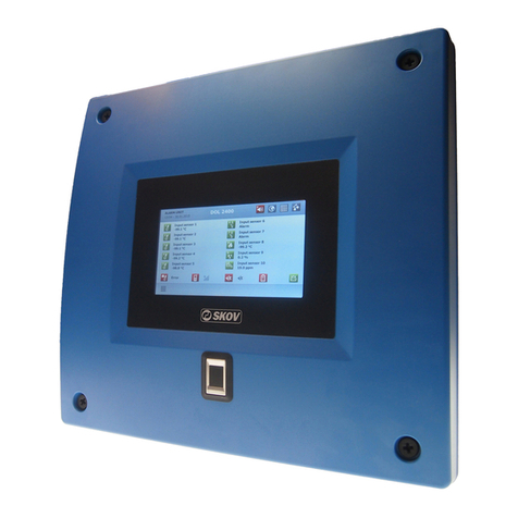
Skov DOL 2100 Manual

DOL 2100 Alarm System
Technical User's Guide


Technical User's Guide
DOL 2100 Alarm System
Program Version
The product described in this manual holds software. This manual corresponds to:
•Software versions: Front: 1.15, Fixed line: 4.05 and GSM: 2.09
It was released in 2014.
Product and Documentation Changes
SKOV A/S reserve the right to change this document and the product herein described without further
notice. In case of doubt, please contact SKOV A/S.
Latest date of change appears from the back page.
In case of misoperation or improper use, ventilation systems can result in production loss
or cause loss of lives among animals.
SKOV A/S recommend that ventilation systems should be mounted, operated and serviced
only by trained staff and that a separate emergency opening unit and an alarm system be
installed as well as maintained and tested at regular intervals, according to SKOV A/S’s
terms and conditions of sale and delivery.
Pre-paid mobile service cards may not be used with DOL 2100 GSM.
NOTE
•All rights reserved. No part of this manual may be reproduced in any manner whatsoever
without the expressed written permission of SKOV A/S in each case.
•SKOV A/S have made reasonable efforts to ensure the accuracy of the information
contained in this manual. Should any mistakes or imprecise information occur in spite of
this, SKOV A/S would appreciate being notified hereof.
•Irrespective of the above, SKOV A/S shall not accept any liability with regard to loss or
damage caused or alleged to be caused by reliance on any information contained herein.
•Copyright 2014 by SKOV A/S.

Technical User's Guide
DOL 2100 Alarm System
1PRODUCT DESCRIPTION 5
2USER’S GUIDE 5
2.1 Operating Panel ...................................................................................................5
2.2 Alarm.....................................................................................................................6
2.2.1 Stop Alarm via Operating Panel ..................................................................................... 6
2.2.2 Stop Alarm via Telephone................................................................................................ 6
2.2.3 Stop Alarm via SMS (only GSM).................................................................................... 6
2.3 Description of Keyboard.....................................................................................7
2.4 Speech Computer................................................................................................8
2.4.1 Scanning Stations.............................................................................................................. 8
2.4.2 Telephone Numbers.......................................................................................................... 8
2.4.3 SMS Alarm........................................................................................................................ 8
2.4.4 Setting of Dial-up Functions ............................................................................................ 9
2.4.5 Input Names .................................................................................................................... 10
2.4.6 Call the Speech Computer –Recording User Words .................................................. 11
2.4.7 Enquiry and remote Control ......................................................................................... 12
2.4.8 Other Speech Computer Setting Options via Telephone ............................................ 13
2.4.9 Interaction with Fax or Modem .................................................................................... 13
2.4.10 Error Messages from the Speech Computer (in Loudspeaker).................................. 14
3INSTALLATION GUIDE 15
3.1 Wiring Diagram ..................................................................................................15
3.1.1 Systems with Fixed-line network or GSM.................................................................... 16
3.1.2 Systems without Fixed-line network or GSM .............................................................. 16
3.1.3 Alarm Outputs ................................................................................................................ 16
3.2 Starting ...............................................................................................................17
3.3 DIPSWITCH on the Computer Board in the Cover..........................................18
3.4 Daily Test of Battery..........................................................................................18
3.5 Station Numbers................................................................................................19
3.6 System with Several Alarm Panels ..................................................................19
4MAINTENANCE 20
4.1 Service................................................................................................................20
4.2 Cleaning..............................................................................................................20
4.3 Removal for Recycling......................................................................................20
5TECHNICAL DATA 21
6AUXILIARY CHARTS 22
7GLOSSARY FOR CHANGING NAME OF INPUT 25

Technical User's Guide 5
DOL 2100 Alarm System
1Product Description
The DOL 2100 alarm system is intended for monitoring of housing equipment and computers and can
monitor up to ten thermostats or alarm relay outputs from, e.g. silos, burners and feeding systems.
DOL 2100 Fixed-line network and DOL 2100 GSM also contain a speech computer which can be used
for clear speech alarm calls.
2User’s Guide
2.1 Operating Panel
Acknowledge alarms.
Test the siren and flashing alarms.
Press the key for 5 seconds to activate test calls.
Press: Start or end a service break.
Press the key for 2 seconds to be able to use the
keyboard as an ordinary phone.
Press: Hear the current voltage on the
battery.
Press the key for two seconds to set the
time for the daily battery test.
Numeric keyboard 1-10
- connect and disconnect the monitoring of
inputs 1-10.
- enter phone numbers.
- set the speech computer.
Lamps
Green
Red
Constant
Flashes
Constant
Flashes
Turned off
Alarm lamp
State OK
System in
service mode
Alarm
acknowledged
Alarm
12VDC-lamp
230 V
operation
Battery test
is running
230 V missing
Battery test fails
Lamps for input
terminals 1-10
State OK
-
Alarm
acknowledged
Alarm
Monitoring
stopped

6Technical User's Guide
DOL 2100 Alarm System
2.2 Alarm
2.2.1 Stop Alarm via Operating Panel
Press
Read the cause of the alarm (see section 2.2.1.1)
Remedy the cause of the alarm
Press again to restart monitoring
2.2.1.1 Alarm causes
Alarm lamp
Input lamps
12 V DC lamp
Input alarm
Flashes red
Flashes red
Battery error
Flashes red
Flashes red
230 V lacks
Flashes red
Constant red
Phase break
Flashes red
2.2.2 Stop Alarm via Telephone
The speech computer calls and says: “Alarm from speech computer”
Press # (acknowledges the alarm)
The speech computer mentions the alarms in question
Please note that some telecom companies use the "#" key as a command. This can disconnect DOL
2100’s messages which then cannot be heard. You can set which key you want to use when
acknowledging the alarm by telephone call (see section 2.4.4, Acknowledge call with...).
2.2.2.1 Redial untill Acknowledgement at the Unit
DOL 2100 includes the function Redial. When this function is active, DOL 2100 redials after the set
period of time until acknowledgement is carried out at the actual alarm unit as described above in
section 2.2.1. When redialling, the call process starts all over again as if it were a new alarm.
The period of time between the the calls can be set from 0-30 minutes. At 0 minutes the function is
inactive. Also see the section 2.4.7.
2.2.3 Stop Alarm via SMS (only GSM)
If the voice computer is set up to SMS alarm, an SMS is sent to the first telephone number activated
for SMS alarm. Also see paragraph 2.4.3.2.
Answer the SMS alarm and send DOL 2100’s password ending with a point; e.g. '1.' (1 is the
factory-set password).
DOL 2100 will acknowledge the alarm and send an SMS text to all phone numbers indicating
that the alarm has been acknowledged, the alarm type and the phone no. that acknowledged.

Technical User's Guide 7
DOL 2100 Alarm System
2.3 Description of Keyboard
This key is used to acknowledge system alarms. Acknowledged alarms are
indicated by the lamp changing from flashing red light to constant red light. If, in
the meantime, the input starts working again, the lamp will change to constant
green when acknowledging by pressing the key.
The speech computer mentions the alarms in the system.
This key is used together with the speech computer to set the system to a service
break. No alarm will be given for the next 60 minutes after which the service
break automatically ends. The service break can be stopped by pressing the
key.
In service break mode, the alarm lamp will flash green while the lamps for the
inputs 1-10 will display the current state of the inputs.
In case of system alarms, an alarm will be triggered when the service break ends.
Alarms occurring before the service break will also be triggered.
Press the key for 2 seconds to be able to use the keyboard as an ordinary phone.
All phone commands can be used. Press 000# to cancel operation.
DOL 2100 automatically prevents operation of the system after 40 seconds of
inactivity.
This key is used to test the alarm outputs. As long as the key is pressed, all
alarm outputs on DOL 2100 will be activated (Alarm relay, Flash and Call
outputs).
Press the key for 5 seconds to activate test calls.
This key is used to set a daily time for the battery test. When setting the time for
the battery test, press the key for approx. two seconds until the 12 V DC
lamp starts flashing green. The battery test will then be carried out every day at
the time set for the function.
The daily test lasts for ten minutes. If the battery voltage drops below 11.5 V, an
alarm is triggered for “battery error”, the 12 V DC lamp flashes red, and the
battery should be replaced immediately. Since the test is carried out every day,
the alarm will be triggered daily until the battery is replaced.
Press the key briefly to hear the current voltage on the battery. However, this
applies only to DOL 2100 Fixed-line network and DOL 2100 GSM.
1-10, *and #
The keys 1-10 are used to start and stop the monitoring of the ten inputs.
The keys are used with the *and #keys to enter phone numbers and other
speech computer settings. When *is pressed, the lamps for the inputs 1 to 10 are
turned off to indicate that the setting of the speech computer is in progress. The
system automatically returns to normal after ten seconds if no entries are made or
the #key is pressed.

8Technical User's Guide
DOL 2100 Alarm System
2.4 Speech Computer
The Fixed-line network and GSM variants contain a speech computer which is also used to monitor
alarms from all the connected panels. The speech computer has a vocabulary of approx. 200 words
used to speak alarms, etc. in both the local loudspeaker and via the telephone.
2.4.1 Scanning Stations
It is important to scan the stations when carrying out the setup. In connection with setup or when
changing the number of control panels, the voice computer must search for the connected stations. The
DOL 2100 includes 11 stations divided among 10 input terminals and one system station.
Hold the # key for 2 sec.
After approx. 2 min. the voice computer states the found stations. Please check that this is correct.
2.4.2 Telephone Numbers
Telephone numbers must be entered before alarm calls can be made. A total of five telephone numbers
of max. 18 digits each can be entered. When a number has been entered, the speech computer will
speak it over the loudspeaker.
Entering a telephone
number 1-5
Check
Delete
*1<telephone number> #
*2<telephone number> #
*3<telephone number> #
*4<telephone number> #
*5<telephone number> #
*1#
*2#
*3#
*4#
*5#
*1*#
*2*#
*3*#
*4*#
*5*#
2.4.3 SMS Alarm
DOL 2100 can transmit an SMS alarm indicating alarm type.
Activate the SMS alarm function by pressing * after the phone number.
Example Press *1<phone number>*#
2.4.3.1 Time between SMS Alarm
If SMS alarm is activated on more telephone numbers, the time between the single SMS texts are sent
can be changed. 0 minutes is the factory-set.
Time between SMS alarm Press *64 <0-5> #
2.4.3.2 Acknowledgement of SMS alarm
Answer the SMS alarm and send DOL 2100’s password ending with a point; e.g. '1.' (1 is the factory-
set password).
DOL 2100 will acknowledge the alarm and send an SMS text to all phone numbers indicating that the
alarm has been acknowledged, the alarm type and the phone no. that acknowledged.

Technical User's Guide 9
DOL 2100 Alarm System
2.4.4 Setting of Dial-up Functions
Setting
Command
Factory
setting
Description
Delay
Press *62 <1-20 min.> #
5 minutes
Delay from occurrence of alarm until the
call starts.
Answer call after
Press *92 <1-10 rings> #
3 rings
Number of rings before thespeech
computer answers thecall.
Call to same no.
Press *95 <1-10 calls> #
3 calls
Number of calls to the same number
before proceeding to the next number
on the list.
Different
persons on duty
Press *97 <nos.1-5> #
No. 1
Calls start at telephone numbers 1-5.
Acknowledge
call with
Key in *65<0-9> #
Key in *65* #
* 65 * #
Select 0-9 as the acknowledgement key
Select # as the acknowledgment key

10 Technical User's Guide
DOL 2100 Alarm System
2.4.5 Input Names
It is possible to change the names of inputs. Up to three
words can be used for each input. Use the “Input names”
chart to indicate the setup. Use the following entry
procedure:
Press *86<station number> *<word> *<word> *
<word>#
See the table to the right for our suggestions for names.
A couple of examples:
Name input 1: Porker house 12
Press *86 1* 402* 410*12#
Name input 5: Feeding system
Press *86 5* 281* 249#
Name inputs 7 and 8: Silo 1 and 2
As silo is not included in the list of words, record
it.
Select word 73. Call the speech computer, enter
the access code and record word number 73 (see
section 2.4.6):
Press *73 0<record the word “Silo”> #
See section 2.4.6.
The new word will now be used as the name for
inputs 7 and 8:
Press *86 7* 73* 99 #
Press *86 8* 73* 2 #
NB Word 1 is pronounced as “one” while word 99 is pronounced as “one” with a different stress.
NB Also see complete glossary for changing name of input terminal, paragraph 7.
In order to have user words displayed in SMS messages, you have to send an SMS reading
*73<user word> #. It is done the same way for other user words.
Name suggestions:
Word numbers
Cooling
192
Controlled_environment
unit
405, 411
Gestation unit
403, 411
Exchanger
179
Farrowing house
401, 410
Feeding system
281, 249
Heating
104
Heating system
104, 249
House
410
Inlet
157
Input
48
Level
194
Mating house
404, 410
Outlet
159
Porker house
402, 410
Power failure
143, 258
Prefinishing
406
Pump
195
Room
43
Ventilation_rate
103
Water
193
Weaner unit
408, 411
Weaner_to_finishing
house
409, 410
Young_female unit
407, 411
Word 73
73
Word 74
74
Word 75
75
Word 76
76
Word 77
77
Word 78
78
Word 79
79
Various figures (1..20)
99, 2, 3, 4, 5…20

Technical User's Guide 11
DOL 2100 Alarm System
2.4.6 Call the Speech Computer –Recording User Words
You can record only by calling the speech computer. When the speech computer answers the call, it
says:
“Welcome to” “speech computer”
Then enter the access code and end using #. The factory-set code is 1. The line is automatically
disconnected after 40 secs. without any activity. After 30 secs., “awaits command” sounds. Press # to
hold the line. Enter 000 # to hang up at once.
Function
Command
Description
Welcome
Press *71 0 <”Welcome to”>#
-press 0 to start and # to stop
Replaces the factory-set “Welcome to”
recording used when calling DOL 2100
Name
Press *72 0 <name>#
-press 0 to start and # to stop
Replaces the factory-set ”Speech computer”
recording used both for outgoing alarm calls
and calls to DOL 2100.
User word
Press *73-79 <User word>#
-press 0 to start and # to stop
User words 73-79 in the word list can be
used to name inputs.
NB The recording period is max. 12 secs., including the user-recorded “welcome to” and the name.
Each word can last max. eight secs.
The name recorded is used in connection with alarm calls. Here, the speech computer says: “Alarm
from” + name.
In order to have name displayed in SMS messages, you have to send an SMS reading
*72<name> #.

12 Technical User's Guide
DOL 2100 Alarm System
2.4.7 Enquiry and remote Control
All units/control panels in the network are accessible. For remote control and enquiries, you can make
use of phone, SMS or DOL 2100 keypad.
Press for 2 sec. on the DOL 2100 before making the entry. It says: “Enter command”.
Function
Command
Description
Enquiry
Station no. * Register no. #
Example:
Listen to the value in a register on a specific
station.
100 * 3 #
Responds with a horn alarm time for station
100 (System).
100 * 12 #
Responds with the battery voltage.
Remote setting
Station no. * Register no. * Value #
Example:
Changes the content of a register on a
specific station.
100*4*5#
Changes the approval time to 5 seconds. This
is the time that passes from the occurrence of
an alarm until it is accepted as an alarm.
The factory setting is 30 sec.
100 * 8 * 10 #
Changes the delay time from the alarm occurs
to the CALL output activates to ten minutes.
100 * 29 * 2359 #
Sets the clock to 11.59 p.m.
Redial
100 *47* <30> #
Redialling after 30 minutes, after
acknowledgement on the phone. Redialling
does not stop until acknowledgement has
been carried out on the control unit.
The factory setting 0 minutes = switched off.
Alarm status
Station no. * #
Enquires about the alarm status for a specific
station.
Example: 1 * #
Responds with the alarm status for station 1
(Input 1).
Start/Stop
monitoring
Station no. * 0 #
Changes the monitoring state on a station.
Example: 1 * 0 #
Starts the alarm monitoring function on station
1 if it has stopped, or stops it if it is activated.
Active alarms
99 * #
Enquires about active alarms in the entire
system. Responds with the number of current
alarms, followed by cause / type and station
name.
In this way, non-acknowledged alarms, if any,
are also acknowledged.
History
99 * * #
Goes to historic mode. ”Alarm memory mode”
sounds.
#
Mentions the most recent alarm and how long
it is since it occurred. Press # again to listen to
older alarms.
* #
Returns to normal mode.
000 #
Disconnects the line to the speech computer.
GSM signal
*993 #
States level and number of masts. Level
should be between -47dBm (good) and -
90dBm (bad). There should at least be two
masts. The signal can be improved by means
of external aerial.

Technical User's Guide 13
DOL 2100 Alarm System
2.4.8 Other Speech Computer Setting Options via Telephone
Function
Command
Factory setting
Description
Access code
*91 <code> #
1
The new access code is spoken. It is
not possible to delete or hear the
code again.
Alarm word
number
*96<word>#
Every ten seconds, the word is spoken
(the sound) in case of an alarm.
Ex. *96 201 #
- Siren sound
Ex. *96 112 #
- ”Alarm”
Ex. *96 79 #
- Word 79 (to be recorded by the
user)
*96 * #
Disconnected
- Disconnects the function.
Alarm speech
*98 <0/1> #
1 (Activated)
In case of system alarms, and if this
function is set to 1, they will be
spoken every minute.
2.4.9 Interaction with Fax or Modem
It is absolutely advisable to connect DOL 2100 to its own separate telephone line to ensure optimum
use. However, DOL 2100 has a function that allows it to interact with a fax and a modem.
Set the speech computer to answer the call before the fax/modem. Call DOL 2100 and hang up
without dialling. For the next minute DOL 2100 will answer the call after three additional rings and in
practise let the fax/modem take over.

14 Technical User's Guide
DOL 2100 Alarm System
2.4.10 Error Messages from the Speech Computer (in Loudspeaker)
It says …
Meaning
”Missing stations”
Telephone numbers HAVE BEEN entered but scanning of
stations has NOT been carried out. (Press the # key for two
secs.).
”Faulty telephone line”
Line voltage alarm or dialling tone alarm
The monitoring function is active only when a telephone
number has been entered.
The telephone line is tested by measuring the voltage
which is approx. 48 V DC in quiescent mode. If the
voltage drops below approx. 5 V, an alarm will be
triggered. Check that the telephones on this line are
working.
If dialling tone monitoring is activated, the test is carried
out by the speech computer answering the call every two
hours, listening for the dialling tone. If there is no tone,
the test will be carried out again every ten minutes for
two hours after which the message ”Telephone line error”
will be given.
Install a separate telephone line if a high degree of safety is vital.
This will also make it easier to call the speech computer.
If this error cannot be avoided, install a dialling tone monitoring
function and disconnect the line voltage monitoring function.
Press *995*# Disconnection of line voltage
monitoring. (*995 1#activates the function)
Press *989 1# Activation of dialling tone monitoring.
(*989*# disconnects the function)
”No dial tone”
When an attempt is made to dial up and the external telephone
line does not provide a dialling tone. Five additional attempts are
made at ten sec. intervals. After a break of 144 secs., the above
procedure is repeated until the line provides a dialling tone again.
”Station xregister ydoes not
answer”
Enquiry about station / register which is not present or does not
answer.
(x * y# has been dialled)
”Out of memory –please erase
word and try again”
The RAM memory has room for no more recordings. A recording
has to be deleted before a new one can be entered. Press * 73
*# deletes word 73
DOL 2100 GSM
”No communication with the
telephone unit” or” The communica-
tion with the telephone unit not valid”
Defective hardware or GSM module.
Defects may result from shield/armouring not being connected to
terminal 16/GND.
”Please enter 1 2 3 4 on the SIM
card”
The PIN code of the SIM card is not 1234.
”The SIM card is missing”
A SIM card is missing in the DOL 2100 GSM module.
”The SIM card is not active, please
enter the PUK code and 1 2 3 4 on
the SIM card”
Enter the PUK code and PIN code = 1234.

Technical User's Guide 15
DOL 2100 Alarm System
3Installation Guide
NB In connection with installation of the alarm system, allowance has to be made for frequency
inverter mounted nearby. In order to avoid noise nuisances from the frequency inverter, a
shielded cable is required between motor and frequency inverter in connection with existing
and new installations of the frequency inverter. The screen must be wired to both the frequency
inverter and the chassis of the motor.
3.1 Wiring Diagram
-
PHONE
INT
EXT
230Vac
123456789101112131415
++
--
SPEAKER
12V DC Supply
GND
+----
NC
COM
NO
16171819202122
A
BRS485
+-------
GND
OUTDOOR
TEMP
1
2324
2
2526
3
2728
4
2930
5
3132
6
3334
7
3536
8910
373839404142
12V DC
FLASH
CALL
434445
+
+
+
+
+
+
+
+
+
+
+
+
0.5 A
0.5 A
+
PELN
12V DC
150
150
150
150
150
150
150
150
150
150
150
-------
10
3839404142
MAIN POWER
MONITORING
RELAY
+
+
-
+
-
-
150
m<2
PE
230 V AC P
N
Only fixed line: Centre
Only fixed line: Local phone
(Max. 30 m) Loudspeaker
(Max. 30 m) 12 V siren
Shield
RS485 to other units
On/Off inputs
DIPSW. 4-ON
Open at alarm
Flashing permanently at alarm (Xenon)
For activation of call to alarm receiving centre
NB: not potential free
E.g. DOL 2012 12 VDC 2.5 A
DIPSW. 4-OFF
Close at alarm
DIPSW. 4-OFF
Open at alarm
Not used by GSM

16 Technical User's Guide
DOL 2100 Alarm System
NB The cable must be shielded/protected from rodent attacks and shield/armouring must be
connected to terminal 16. SKOV A/S recommends using type YSY-JZ.
NB When connecting an external battery, cut the female push-on receptacle off the existing wire
and extend it to the external battery.
TIP If a multiple cable is used, + can be used as a common conductor, BUT Dipswitch 4 must then
be set to ON and the resistors left out (non-monitored line!).
3.1.1 Systems with Fixed-line network or GSM
If there is a DOL 2100 Fixed-line network or GSM in a system with several panels, connect
all the panels in a RS485 network. Connect A to A, B to B and connect the shield in all the
panels to GND. In this way, the integrated speech computer can monitor the alarms of the
other panels. An alarm on an arbitrary panel will then make all the panels activate the alarm
outputs and the siren will then only have to be connected to that specific panel (to be
connected to a panel with power supply).
The loudspeaker should be placed locally at the panel with Fixed-line network or GSM.
The maximum distance between DOL 2100 Fixed-line network, GSM or Basis and the DOL
2100 extension is 10 m. For longer distances, use DOL 2100 Basis with its own battery.
The station numbers must be different on all the panels. See section 3.5.
3.1.2 Systems without Fixed-line network or GSM
Alarm outputs of systems without Fixed-line network or GSM must be connected in parallel
or separate sirens must be mounted on the alarm relay outputs. If there is no Fixed-line
network or GSM, each panel operates on its own.
Here, the station numbers are without significance.
The maximum distance between DOL 2100 Basis and the DOL 2100 extension is 10 m. For
longer distances, use DOL 2100 Basis with its own battery.
3.1.3 Alarm Outputs
When an alarm is triggered:
The alarm relay and FLASH output activate.
The alarm relay turns off after expiry of the Horn alarm time which is set on the dipswitch.
After five minutes the CALL output activates. This output is designed for use with external
call equipment, e.g. an ATU card for the alarm receiving centre.
When acknowledging alarms, the CALL output terminals are reset to normal status and the siren stops.
The FLASH output terminal is active as long as there is an error on an input terminal.

Technical User's Guide 17
DOL 2100 Alarm System
3.2 Starting
The following is to be carried out as a minimum:
DOL 2100 Fixed-line network
1. Scan stations; press the #key for two seconds. After approx. two minutes, the speech
computer states the located stations. Please check that this is correct.
2. Enter phone numbers (see section 2.4.2)
3. Record the name of the place monitored by the system (see section 2.4.6)
4. Choose and enter a new password, see section 2.4.8
Use the User entry chart (section 7) to review the points to be considered
DOL 2100 GSM
Pre-paid mobile service cards may not be used with DOL 2100 GSM.
Switch off the power to DOL 2100. Place the SIM card in DOL 2100 (top right corner).
1. Scanning of stations, hold the # key for 2 seconds. The speech computer says "Please do not
make any entries for the next 2 minutes". Check after scanning that the speech computer
mentions all the stations connected (11 stations per DOL 2100 panel).
2. Enter PUK code (* 1 ** 05 * <PUK code> #). see section 2.4.10.
3. Enter telephone number, see section 2.4.2
4. Enter the name of the place monitored by the system, see section2.4.6.
5. Check GSM signal, see section 2.4.7.
6. Select and enter a new password, see section 2.4.8.

18 Technical User's Guide
DOL 2100 Alarm System
3.3 DIPSWITCH on the Computer Board in the Cover
Factory setting
DIPSWITCH
No.
1
OFF
2
OFF
Selecting a station number (see section 3.5).
3
OFF
4
OFF: 150 Ω resistance in cable.
Monitored line. Possible to detect both
short-circuits and disconnections.
ON: Without resistors
Non-monitored line.
Can only detect disconnections.
5
OFF: No battery test
ON: Battery test
Only the panels with an integrated
supply need to have their battery
test function activated.
1 min.
2 min.
3 min.
Constantly
activated
6
OFF
ON
OFF
ON
Setting the duration of the horn alarm.
7
OFF
OFF
ON
ON
8
OFF: -
ON: -
Bold type indicates factory setting.
3.4 Daily Test of Battery
The 230 V power supply keeps the battery charged for use in case of a power failure. Set dipswitch no.
5 to ON for automatic testing of the battery.
Press the key for two seconds until the 12 V DC lamp starts flashing. DOL 2100 will then
disconnect the 230 V supply daily and the battery will be loaded by power resistors. The test lasts for
ten minutes, however, only until the first alarm state occurs. If the voltage drops below 11.5 V, an
alarm will be triggered.
NB: DOL 2100 does not contain an actual clock. The inner clock is based on software and is not
completely accurate.
If there is a DOL 2200 in the alarm system, it is a good idea to leave it up to the speech computer to
update the clocks in DOL 2100. This can be done by calling the speech computer and entering the
following command:
*997<DOL 2200 system station number> #
The speech computer will then get the time from DOL 2200 at regular intervals and transmit it to all
the DOL 2100 panels. The test will then be carried out between 8.00 a.m. and 8.10 a.m.
O
N
O
F
F
1 2 3 4 5 6 7 8

Technical User's Guide 19
DOL 2100 Alarm System
3.5 Station Numbers
Each input has a separate station number so that the speech computer can indicate where an error has
occurred. The numbers are arranged automatically in series which are determined when the station
number is assigned to the system.
The system has a number to allow system errors to be indicated (errors related to battery, phase
breaks, etc.).
Dipswitch
System
station number
Inputs are automatically assigned the following station
numbers
1
2
3
0
0
0
100
1-10
1
0
0
101
11-20
Extra alarm panels
0
1
0
102
21-30
1
1
0
103
31-40
0
0
1
104
41-50
1
0
1
105
51-60
0
1
1
106
61-70
1
1
1
107
71-80
3.6 System with Several Alarm Panels
Remember to assign numbers to additional alarm panels in continuation of the main station numbers.
The system station numbers are set consecutively to 100, 101, 102, etc.
Changing acceptance duration (30 sec.) and redial (0 min. = switched off) must be set on each control
panel, system station no. 100, 101 etc.
System station no. 100
System station no. 101
System station no. 102
Station nos.
1-10
RS485
12 V
Station nos.
11-20
RS485
12 V
Station nos.
21-30
RS 485
12 V
Main station

20 Technical User's Guide
DOL 2100 Alarm System
4Maintenance
It is important to maintain and test the alarm system in accordance with the rules of the
insurance company.
4.1 Service
Test the alarm system according to the following procedure:
1) Select the input to be tested
2) Read alarm activation
3) Activate the alarm
4) Check that the alarm activates as expected (horn, siren, beep, etc.)
5) Check that telephone calls are made to the entered numbers
6) Stop the alarm (via the # phone key (see section 2.2.2) or the alarm system key)
7) Acknowledge on the chart for completed test
DOL 2100 is maintenance-free; however, the battery deteriorates in the course of time and must
therefore at least be replaced every three years. Check the date label on or at the battery.
Replace the ventilation plugs at the same time as the battery.
The battery can be checked automatically and an alarm be given if the battery is defective. If this is the
case, replace the battery immediately.
4.2 Cleaning
Clean DOL 2100 with a firmly wrung cloth without the use of solvents. Do not expose it to direct
water jets or high-pressure cleaning.
As for all electronic equipment it is best for DOL 2100 to be connected all the time as this will prolong
its life and keep it dry and free from condensation.
4.3 Removal for Recycling
Products supplied by SKOV A/S, suitable for recycling, have a pictorial marking in
form of a dustbin with a cross over. See picture.
Customers can dispose of SKOV products at local collecting points/recycling stations according to
local directions. The recycling station will then arrange for further transport to a certified plant with
view to recycling, reclaim and reuse.
Table of contents
Other Skov Security System manuals