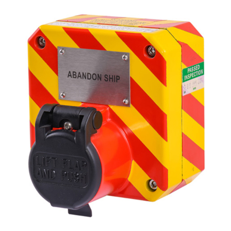
Eaton SM87BG User manual

Call points SM87BG/PB
Technical manual

ii CALL POINTS SM87BG/PB TM146 January 2023 www.eaton.com
DISCLAIMER OF WARRANTIES AND LIMITATION OF LIABILITY
The information, recommendations, descriptions and safety notations in this document are based on Eaton Corporation’s
(“Eaton”) experience and judgment and may not cover all contingencies. If further information is required, an Eaton sales
office should be consulted. Sale of the product shown in this literature is subject to the terms and conditions outlined in
appropriate Eaton selling policies or other contractual agreement between Eaton and the purchaser.
THERE ARE NO UNDERSTANDINGS, AGREEMENTS, WARRANTIES, EXPRESSED OR IMPLIED, INCLUDING
WARRANTIES OF FITNESS FOR A PARTICULAR PURPOSE OR MERCHANTABILITY, OTHER THAN THOSE
SPECIFICALLY SET OUT IN ANY EXISTING CONTRACT BETWEEN THE PARTIES. ANY SUCH CONTRACT STATES THE
ENTIRE OBLIGATION OF EATON. THE CONTENTS OF THIS DOCUMENT SHALL NOT BECOME PART OF OR MODIFY
ANY CONTRACT BETWEEN THE PARTIES.
In no event will Eaton be responsible to the purchaser or user in contract, in tort (including negligence), strict liability or
other-wise for any special, indirect, incidental or consequential damage or loss whatsoever, including but not limited to
damage or loss of use of equipment, plant or power system, cost of capital, loss of power, additional expenses in the
use of existing power facilities, or claims against the purchaser or user by its customers resulting from the use of the
information, recommendations and descriptions contained herein. The information contained in this manual is subject to
change without notice.

iii
Call points SM87BG/PB
English
CALL POINTS SM87BG/PB TM146 January 2023 www.eaton.com
Contents
1.0 INTRODUCTION. . . . . . . . . . . . . . . . . . . . . . . . . . . . . . . . . . . . . . . . . . . . . . . . . . . . . . . . . . . . . . . . . . . . . .1
2.0 INSTALLATION.......................................................................1
General ................................................................................... 1
Cable termination ........................................................................... 1
3.0 OPERATION .........................................................................2
4.0 MAINTENANCE ......................................................................4
5.0 CERTIFICATION/APPROVALS ...........................................................4
IECEx units ................................................................................ 4
ATEX units ................................................................................. 4
6.0 FUNCTIONAL SAFETY ................................................................4
Introduction ................................................................................ 4
Assessment of functional safety................................................................ 4
Conditions of Safe use ....................................................................... 5

iv CALL POINTS SM87BG/PB TM146 January 2023 www.eaton.com

1
Call points SM87BG/PB
English
CALL POINTS SM87BG/PB TM146 January 2023 www.eaton.com
1.0 Introduction
These manual fire alarm, emergency shutdown breakglass
and pushbutton units have been designed for the most
arduous environmental conditions. The units are both easy
to install and maintain. A choice of either stainless steel
or alloy makes the range suitable for both the offshore
and onshore industries.
The units are available with the following options and
features:
Lift flap
Duty label
Tag label
Earth continuity via internal/external earth studs
LED
End of Line and Series resistors and diodes
Switches (two switches, four poles maximum)
M20 or M25 gland entries in a range of positions, with a
maximum of four
Optional momentary or latching with key reset actions
2.0 Installation
General
A red high intensity LED can be fitted for alarm indication
when ordered from MEDC. As standard the LED is not
provided with over current protection. The forward current
(If) should be limited to 20mA.
When installing and operating explosion-protected
equipment, requirements for selection, installation
and operation should be referred to e.g. IEE Wiring
Regulations and the ‘National Electrical Code’ in North
America. Additional national and/or local requirements
may apply.
Ensure that all nuts, bolts and fixings are secure.
Ensure that only the correct listed or certified stopping
plugs are used to blank off unused gland entry points and
that the NEMA/IP rating of the unit is maintained. MEDC
recommend the use of a sealing compound such as
HYLOMAR PL32 on the threads of glands and stopping
plugs in order to maintain the IP rating of the unit.
These alarm call points are designed to be directly
mounted using the 4 off 9mm holes in the base of the unit.
Units may be mounted to vertical, horizontal or angled
surfaces.
The holes have been designed to accept an M8 screw or
bolt. MEDC recommend the use of stainless steel screws.
A red high intensity LED can be fitted for alarm indication
when ordered from MEDC. As standard the LED is not
provided with over current protection. The forward current
(If) should be limited to 20mA.
Cable termination
CAUTION: Before removing the cover assembly,
ensure that the power to the unit is isolated.
Unscrew and remove the 4 off M6 screws (5.0mm A/F
hexagon key) holding the cover assembly to the base.
Keep in a safe, accessible location.
Twist the cover assembly gently clockwise and
anti-clockwise, whilst pulling it away from the base.
Remove to gain access to the interior.
Cable termination should be in accordance with
specifications applying to the required application. MEDC
recommends that all cables and cores should be correctly
identified. Please refer to the wiring diagram provided
with the product.
Ensure that only the correct listed or certified cable glands
are used and that the assembly is shrouded and correctly
earthed.
All cable glands should be of an equivalent NEMA/IP
rating to that of the call point and integrated with the unit
such that this rating is maintained.
The internal earth terminal, where fitted, must be used
for the equipment grounding connection and the external
terminal is for a supplementary bonding connection
where local codes or authorities permit or require such a
connection.
Once termination is complete, carefully push the cover
assembly back onto the base, avoiding damage to the
mating surfaces. Ensure that the retaining strap is not
trapped between the mating surfaces and that the o-ring
is correctly seated in its groove. Ensure the retaining
strap and wires are clear of the microswitch actuator
and operating mechanism. Replace the 4 off M6 screws
(5.0mm A/F hexagon key) into the holes in the cover
assembly and tighten evenly. Ensure the maximum gap
of 0.15mm is maintained between the cover and the base
once assembled.
Purchaser/Customer should make Eaton aware of any
external effects or aggressive substances that the
equipment may be exposed to.
Ensure equipment is protected from direct dust laden
airflow which may cause charge transfer.

2
Call points SM87BG/PB
English
CALL POINTS SM87BG/PB TM146 January 2023 www.eaton.com
3.0 Operation
The operating voltage of the unit is stated on the unit label.
SM87BG General arrangement
SM87BG units - operation
The unit is operated by breaking the glass element in the
front of the cover using the hammer attached to the unit.
If a lift flap has been specified, this will need to be raised
first to gain access to the glass element.
SM87BG unit - resetting procedure
a. To replace the glass, a kit containing O-rings and glass
is provided.
b. Unscrew and remove the circular bezel on the front of
the unit.
c. Remove the original O-rings and glass and ensure the
grooves in the bezel and cover are clean.
d. Fit the larger O-ring into the groove on the cover.
e. Fit the smaller O-ring into the groove on the underside
of the bezel:-
I. Offer the O-ring up to the groove.
II. Place thumbs of both hands side by side onto
the O-ring.
III. Press the O-ring down into the groove circumference
maintaining even pressure, forcing the O-ring into the
groove.
IV. The O-ring should be fully seated in the groove and
not fall out when fitting the bezel to the cover.
V. Centralise the new glass element on the cover
f. Place the new glass element into position on the
cover and assemble the bezel over the top of the glass
element.
g. Ensure the glass element stays central on the cover
by holding down the glass with thumb through the
hole in the centre of the bezel.
h. Carefully use the glass element to depress the
plunger until the glass is in full contact with the cover
O-ring. Ensure there is an even gap around the glass.
Without allowing the glass element to move, screw
down the bezel until the bottom of the bezel is
tightened against the cover.

3
Call points SM87BG/PB
English
CALL POINTS SM87BG/PB TM146 January 2023 www.eaton.com
SM87PB General arrangement
SM87PB units - operation
The unit is operated by lifting the flap on the front of the
cover, then depressing the steel actuator underneath.
Depending on the unit type ordered, the actuator will
either remain in its depressed position (latching versions)
or return to its original position (momentary versions).
SM87PB units - resetting procedure
On units with a latching mechanism, once operated,
the actuator remains in its depressed position. To reset
the call point, lift the flap on the front of the cover and
insert the key (provided with the unit) into the slot in
the front face of the actuator. The key should be turned
slightly to locate it in the actuator and pulled back to the
initial position. The key can then be removed and the
flaplowered.
SM87PB Turn and push general arrangement
122 ±1
122 ±1
105 ±1 CRS
105 ±1 CRS
'T'
'B'
'R'
'L'
DUTY LABEL
TAG LABEL
(OPTIONAL)
9
1 FIXING HOLES
4 POSITIONS
36.5 ±1 (A)
30 ±1 (S)
87.5 ±2 (A)
81 ±2 (S)
138.5 ±3 (A)
132 ±3 (S)
SM87PB Turn & push - operation
The unit is operated by lifting the flap on the front cover,
then turning the actuator clockwise 90° and depressing
the actuator. The actuator will remain in its depressed
position.
SM87PB Turn & push – resetting procedure
Once operated the actuator remains in its depressed
position. To reset the call point, lift the flap on the front
cover and pull the actuator out from its depressed
position. Turn the actuator anti-clockwise 90°. The lift flap
can then be lowered.

4
Call points SM87BG/PB
English
CALL POINTS SM87BG/PB TM146 January 2023 www.eaton.com
4.0 Maintenance
During the working life of the unit, it should require little
or no maintenance. However, if abnormal or unusual
environmental conditions occur due to plant damage or
accident etc., then visual inspection is recommended.
If the unit requires cleaning, then only clean exterior
with a damp cloth to avoid electro-static charge build
up. If a unit fault should occur, then the unit can be
repaired by MEDC. All parts of the unit are replaceable.
If you acquired a significant quantity of units, then it
is recommended that spares are also made available.
Please discuss your requirements with the Technical Sales
Engineers at MEDC.
SM87PB spares
Description Part No.
2 Pole Microswitch PX99900457
3 Pole Microswitch PX99900477
Cover O-ring PX99900233
Lift flap and pin kit Contact MEDC
Cover screw for st. steel unit (4 off required) PX99900584
Cover screw for alloy unit (4 off required) PX99900818
Reset key (Not shown) PX99900108
5.0 Certication/approvals
IECEx units
Certified to IEC 60079-0, IEC 60079-1 and IEC 60079-31
Ex d unit (IEC certification No. IECEx BAS 09.0060)
Ex d IIC T6 (-55°C to +55°C) Gb
Ex tb IIIC T85°C (-55°C to +55°C) Db IP66/IP67
or
Ex d IIC T5 (-55°C to +70°C) Gb
Ex tb IIIC T100°C (-55°C to +70°C) Db IP66/IP67
The IECEx certificate and product label carry the IECEx
equipment protection level marking
Gb
Db
Where:
Gb signifies suitability for use in a Zone 1 surface
industries area in the presence of gas.
Db signifies suitability for use in a Zone 21 surface
industries area in the presence of dust
ATEX units
Certified to EN60079-0, EN60079-1 and EN60079-31
Ex d unit (ATEX certification No. Baseefa03ATEX0075)
Ex d IIC T6 (-55°C to +55°C) Gb
Ex tb IIIC T85°C (-55°C to +55°C) Db IP66/IP67
or
Ex d IIC T5 (-55°C to +70°C) Gb
Ex tb IIIC T100°C (-55°C to +70°C) Db IP66/IP67
The ATEX certificate and product label carry the ATEX
group and category marking:
II 2 GD
Where:
Signifies compliance with ATEX
II Signifies suitability for use in surface industries
2 Signifies suitability for use in a zone 1 area
G Signifies suitability for use in the presence of gases
D Signifies suitability for use in the presence of dust
DNV Type approved (SM87PB only). Approved
according to IEC60945: Maritime navigation and radio
communication equipment and systems.
The equipment is classed as exposed.
Minimum compass safe distance is 5m.
6.0 Functional safety
Introduction
The SM87PB Call Point has been designed for use
in potentially explosive atmospheres and harsh
environmental conditions. The marine grade alloy or
stainless enclosures are for use offshore or onshore,
where light weight combined with corrosion resistance
and strength is required.
The function of the call point is to raise an alarm manually
once verification of a fire or emergency condition exists,
by pushing the button.
The safety function of the SM87PB Call Point is to raise
the alarm when the Button is pressed.
Under No fault (Normal) Operating conditions the
SM87PB Push Button Unit will raise the alarm upon
operating the switch via pushing the button.
Under fault conditions the failure mode of the Push
Buttons is a failure to raise the alarm. For the failure rate
associated with this failure mode please refer to the
tablebelow.
Assessment of functional safety
The SM87PB Call Point is intended for use in a safety
system conforming to the requirements of IEC61508.
UL has conducted a Failure Modes Effect and Diagnostic
Analysis (FMEDA) of the SM87PB Push Button unit
against the requirements of IEC61508-2 using a proof test
interval of 8760hrs.
The results are shown below and are based on Route 1H.
The Call Point is classed as a Type A device.

5
Call points SM87BG/PB
English
CALL POINTS SM87BG/PB TM146 January 2023 www.eaton.com
SM87PB Pushbutton
Safety Function of SM87PB Push Button:
‘To raise the alarm upon pushing the button’
Architectural constraints: Type A
HFT= 0
SFF= 79.7%
Proof Test Interval
=8760Hrs
MTTR = 8 Hrs
SIL2
Random hardware failures: λDD = 0
λDU = 3.43E-08
λSD = 0
λSU = 1.34E-07
Probability of failure on demand: PFDAVG= 1.50E-04
(Low Demand Mode)
SIL3
Probability of Dangerous failure on safety
function: PFH = 3.43E-08
(High Demand Mode)
SIL3
Hardware safety integrity compliance[1] Route 1H
Systematic safety integrity compliance Route 1S
Systematic Capability SC2
Overall SIL-capability achieved SIL 2 (Low Demand)*
SIL 2 (High Demand)*
*Limited to SIL 2 due to SFF value
Conditions of Safe use
The following conditions apply to the installation,
operation and maintenance of the assessed equipment.
Failure to observe these may compromise the safety
integrity of the assessed equipment:
1. The user shall comply with the requirements given
in the manufacturer’s user documentation (This
Safety Manual and Technical manual) in regard to all
relevant functional safety aspects such as application
of use, installation, operation, maintenance, proof
tests, maximum ratings, environmental conditions,
repair,etc;
2. Selection of this equipment for use in safety functions
and the installation, configuration, overall validation,
maintenance and repair shall only be carried out by
competent personnel, observing all the manufacturer’s
conditions and recommendations in the user
documentation.
3. All information associated with any field failures
of this product should be collected under a
dependability management process (e.g., IEC
60300-3-2) and reported to the manufacturer.
4. The unit should be tested at regular intervals to
identify any malfunctions; in accordance with this
safety manual.

6CALL POINTS SM87BG/PB TM146 January 2023 www.eaton.com
Call points SM87BG/PB
русский
Contents
1.0 ВВЕДЕНИЕ ............................7
2.0 УСТАНОВКА .................................................7
Общая информация 7
Кабельный ввод 7
3.0 ЭКСПЛУАТАЦИЯ ....................................................................8
4.0 ТЕХОБСЛУЖИВАНИЕ ................................................................9
5.0 СЕРТИФИКАЦИЯ/АТТЕСТАЦИЯ.......................................................10
Устройства класса 1ЕСЕх 10
Устройства кʌʌасса АТЕХ: 10

7CALL POINTS SM87BG/PB TM146 January 2023 www.eaton.com
Call points SM87BG/PB
русский
1.0 Введение
Настоящие устройства ручной пожарной сигнализации,
предусматривающие разбивание стекла и нажатие
кнопки аварийного выключения, разработаны для
самых тяжелых условий окружающей среды Эти
устройства легко и устанавливать, и обслуживать
Возможность выбора в качестве конструкционного
материала нержавеющей стали или сплава позволяет
использовать их в отраслях промышленности, где
работы могут производиться как в морских условиях,
так и на суше
Устройства выпускаются со следующими
возможностями и функциями:
Подъемный щиток
Ярлык с рабочими характеристиками
Этикетка с маркировкой
Заземление при помощи внутренних/наружных
заземляющих штырей
СИД
Конечные и добавочные резисторы и диоды
Переключатели (два переключателя с числом полюсов
до четырех)
Сальниковые вводы размером М20 или М5 в
положениях, максимальное число которых не
превышает четырех
Предусмотренные отдельным заказом
кратковременные или фиксируемые действия с
возвратом в исходное состояние с помощью ключа
2.0 Установка
Общая информация
Требования, предъявляемые к выбору, установке и
эксплуатации взрывозащищенного оборудования,
должны соответствовать «Нормативным требованиям
к монтажу электрических схем Института
инженеров-электриков (IEE)» и «Национальным
электротехническим нормативам» для Северной
Америки Необходимо учитывать также наличие
дополнительных федеральных и (или) местных
требований
Проследите, чтобы все гайки, болты и крепления были
надежно затянуты
Проследите, чтобы для заглушки неиспользуемых
сальниковых вводов использовались только правильно
каталогизированные или сертифицированные
заглушки и чтобы был выдержан класс защиты
NEMA/IP устройства Компания MEDC рекомендует
нанести герметик HYLOMAR PL32 на резьбу
сальников и заглушек с целью сохранения класса
защиты IPустройстваДанные тревожные извещатели
рассчитаны на установку с использованием 4
отверстий размером
9 мм в базовой части устройства
Устройства могут монтироваться на вертикальных,
горизонтальных поверхностях, а также на
поверхностях, расположенных под углом к вертикали
Отверстия рассчитаны под винты или болты размером
М8 MEDC рекомендует использовать винты из
нержавеющей стали
Кабельный ввод
ОСТОРОЖНО! Перед снятием узла крышки
убедитесь в том, что питание устройства
отключено.
Выверните 4 винта Мб (размер зева шестигранного
ключа — 5,0мм), удерживая крышку в сборе на
установочной поверхности Храните их в безопасном,
легкодоступном месте Осторожно поворачивайте
крышку в сборе по часовой стрелке и против нее, при
этом вытаскивая ее из базовой части Удалите ее,
чтобы получить доступ к внутреннему пространству
Кабельный ввод должен соответствовать
спецификациям, разработанным для конкретной
прикладной задачи MEDC рекомендует, чтобы все
кабели и жилы кабелей были должным образом
идентифицированы См схему электропроводки,
поставляемую вместе с изделием Проследите, чтобы
использовались только правильно каталогизированные
или сертифицированные кабельные уплотнения и
чтобы узел был экранирован и правильно заземлен
Все кабельные уплотнения должны соответствовать
классу защиты NEMA/IP извещателя и быть встроены в
устройство, как того требует этот класс
Внутренняя клемма заземления там, где она
установлена, должна использоваться для
заземления оборудования, а внешняя клемма — для
дополнительного заземления там, где местные законы
или власти позволяют или требуют наличия такого
соединения
По завершении заделки с большой осторожностью
поместите крышку в сборе обратно на основание,
стараясь не повредить сопрягающиеся поверхности
Проследите, чтобы фиксирующая скоба не попала
между сопрягающимися поверхностями и чтобы
кольцевое уплотнение правильно село в свою канавку
Проследите, чтобы фиксирующая скоба и провода не
задевали привод микропереключателя и управляющий
механизм Установите 4 винта размером Мб (размер
зева шестигранного ключа — 5,0мм) обратно в
отверстия узла крышки и равномерно их затяните
Проследите, чтобы между крышкой и основанием был
выдержан зазор величиной не более 0,15мм
Покупатель/заказчик обязан проинформировать
Eaton обо всех внешних воздействиях и агрессивных
веществах, которым оборудование будет подвергаться
во время эксплуатации
Убедитесь, что оборудование защищено от
насыщенного пылью потока воздуха, который может
привести к переносу заряда

8CALL POINTS SM87BG/PB TM146 January 2023 www.eaton.com
Call points SM87BG/PB
русский
3.0 Эксплуатация
Рабочее напряжение устройства приведено на его этикетке
Общая компоновка SM87BG
Устройства SM87BG — эксплуатация
Для управления устройством необходимо разбить
стекло в передней части крышки при помощи
молотка, прилагаемого к устройству В случае если
был предусмотрен подъемный щиток, чтобы получить
доступ к стеклу, щиток необходимо предварительно
поднять
Устройство SM87BG — процедура сброса
a Для замены стекла поставляется комплект,
содержащий кольцевые уплотнения и само стекло
b Выверните и снимите круглую лицевую панель в
передней части устройства
c Снимите исходные кольцевые уплотнения и стекло
и проследите, чтобы канавки в лицевой панели и
крышке были чистыми
d Установите кольцевое уплотнение большего
размера в канавку на крышке
e Установите кольцевое уплотнение меньшего
размера в канавку на обратной стороне лицевой
панели:-
I Разместите кольцевое уплотнение на канавке
II Положите большие пальцы обеих рук рядом друг с
другом на кольцевое уплотнение
III Равномерно нажимая на кольцевое уплотнение по
всему контуру, вставьте его в канавку
IV Кольцевое уплотнение должно полностью сесть
в канавку и не должно выпадать при установке
лицевой панели на крышку
V Отцентрируйте положение нового стекла
на крышке
f Установите новое стекло в надлежащее
положение на крышке, а поверх стекла установите
лицевую панель
g Обеспечьте центральное положение стекла на
крышке, прижимая и удерживая его большим
пальцем через отверстие в центре лицевой панели
h Осторожно надавливайте стеклом на шток, пока
оно не войдет в полный контакт с кольцевым
уплотнением крышки Проследите, чтобы зазор
вокруг стекла был равномерным
Не сдвигая стекла, вворачивайте лицевую панель
до тех пор, пока ее дно не будет прижато к крышке

9CALL POINTS SM87BG/PB TM146 January 2023 www.eaton.com
Call points SM87BG/PB
русский
Общая компоновка SM87PB
Устройства SM87PB — эксплуатация
Для управления устройством необходимо поднять
щиток, расположенный перед крышкой, и нажать
на стальной пускатель, находящийся под ним
Взависимости от типа заказанного устройства
пускатель либо останется в нажатом положении
(версии с фиксацией пускателя), либо вернется в
исходное (версии с кратковременным нажатием)
Устройства SM87PB — процедура сброса
В устройствах с механизмом фиксации нажатый
пускатель остается в нажатом положении Чтобы
восстановить готовность извещателя, поднимите
щиток на передней крышке и вставьте ключ
(поставляется вместе с устройством) в щель на
передней стороне пускателя Ключ следует слегка
повернуть, чтобы установить его в пускателе, затем
потянуть назад и вернуться в исходное положение
Затем можно извлечь ключ и опустить щиток
Общая компоновка SM87PB поворотно - нажимного типа
122 ±1
122 ±1
'T'
'B'
'R'
'L'
36.5 ±1 (A)
30 ±1 (S)
87.5 ±2 (A)
81 ±2 (S)
138.5 ±3 (A)
132 ±3 (S)
ЭTИКETКA C MAPКИPOBКOЙ
(OПЦИЯ)
ЯPЛЬIК C PAБOЧИMИ
XAPAКTEPИCTИКAMИ
УCTAHOBOЧHЬIE OTBEPCTИЯ
9±1 4’ПOЛOЖEHИЯ
105 ±1 PACCTOЯHИE
MEЖДУ ЦЕHTPAMИ
105 ±1 PACCTOЯHИE
MEЖДУ ЦЕHTPAMИ
Извещатель SM87PB поворотно-нажимного типа-
Включение
Для того чтобы включить устройство, поднимите
откидную крышку на передней панели, после чего
поверните рукоятку по часовой стрелке на 90° и
утопите ее Рукоятка останется в нажатом положении
Извещатель SM87PB поворотно-нажимного типа - Сброс
После включения рукоятка останется в нажатом
положении Для того чтобы выполнить сброс ручного
извещателя, поднимите откидную крышку на передней
панели и потяните рукоятку, чтобы вернуть ее в
исходное положение Поверните рукоятку против
часовой стрелки на 90° Опустите откидную крышку
4.0 Техобслуживание
В течение всего срока службы устройству необходимо
минимальное техобслуживание или вообще не
требуется никакого техобслуживания Однако, если,
например, из-за повреждения или аварии установки
возникают аномальные или необычные условия
окружающей среды, рекомендуется производить
визуальный осмотр
Если устройство нуждается в очистке, производите ее
только для внешней его поверхности, используя для
этого кусок влажной ткани во избежание накопления
электростатического заряда

10 CALL POINTS SM87BG/PB TM146 January 2023 www.eaton.com
Call points SM87BG/PB
русский
Если в работе устройства происходят сбои, его можно
отремонтировать в компании MEDC Может быть
заменена любая деталь устройства
Если вы приобретаете большое количество устройств,
рекомендуется иметь необходимый доступ к
соответствующим запасным частям Обсудите
свои требования с инженерами службы сбыта
компанииMEDC
5.0 Сертификация/аттестация
Устройства класса 1ЕСЕх
Сертифицированы на соответствие стандартам IEC
60079-0, IEC 60079-1 и IEC 60079-31
Устройство Ex d (сертификация IEC № lECEx BAS
090060)
Ex d IIC Тб (от -55 °C до +55 °C) Gb
Ex tb IIIC T85 °C (от -55 °C до +55 °C) Db IP66/IP67
ИЛИ
Ex d IIC T5 (от -55 °C до +70 °C) Gb
Ex tb IIIC T100 °C (от -55 °C до +70 °C) Db IP66/IP67
В сертификате lECEx и на этикетке изделия
содержится маркировка lECEx уровня защиты
оборудования
Gb
Db
Где:
Gb означает возможность применения в наземных
промышленных условиях Зоны 1 в присутствии газа
Db означает возможность применения в наземных
промышленных условиях Зоны 21 в присутствии пыли
Запчасти SM87
Описание Деталь №
2-полюсный микропереключатель РХ99900457
3-полюсный микропереключатель РХ99900477
Уплотнительное кольцо крышки РХ99900233
Откидная заслонка и комплект
контактов Контакт MEDC
Винт крышки для блока из нерж стали
(требуется 4) РХ99900584
Винт крышки для блока из сплава
(требуется 4) РХ99900818
Кнопка сброса (Не показано) РХ99900108
Устройства кʌасса АТЕХ:
Сертифицированы на соответствие стандартам
EN60079-0, EN60079-1 и EN60079-31
Устройство Ex d (сертификация АТЕХ №
Baseefa03ATEX0075)
Ex d IIC Тб (от -55 °С до +55 °С) Gb
Ex tb IIIC T85 °C (от -55 X до +55 °C) Db IP66/IP67
ИЛИ
Ex d IIC T5 (от -55 °C до +70 °C) Gb
Ex tb IIIC T100 °C (от -55 X до +70 °C) Db IP66/IP67
В сертификате АТЕХ и на этикетке изделия содержится
маркировка, характеризующая группу и категорию АТЕХ:
II 2 GD
Где:
означает соблюдение требований АТЕХ
II означает возможность использования в наземных
промышленных условиях
2 означает возможность использования в условиях
Зоны 1
G означает возможность использования в
присутствии газов
D означает возможность использования в
присутствии пыли
Сертификат типовых испытаний DNV (SM87PB)
Сертификат соответствия IEC6945:
Оборудование для морской навигации и
радиосвязи
Оборудование классифицируется как открытое
Минимальное безопасное расстояние до компасов
составляет 5 м
Введение
Ручной извещатель SM87PB предназначен для
использования в потенциально взрывоопасных средах
и тяжелых условиях окружающей среды Корпус из
морского сплава или нержавеющей стали пригоден для
использования как на море, так и на суше, в условиях,
где требуется малый вес в сочетании с устойчивостью
к коррозии и прочностью
Ручной извещатель предназначен для подачи
аварийного сигнала вручную при подтверждении
возгорания или аварийной ситуации путем нажатия
кнопки Функция обеспечения безопасности,
выполняемая ручным извещателем SM87PB,
заключается в подаче аварийного сигнала при
нажатии кнопки
В безотказном (нормальном) рабочем состоянии
кнопочный извещатель SM87PB подаст аварийный
сигнал при срабатывании выключатели после
нажатии кнопки Режим отказа кнопочного
выключателя означает отсутствие подачи аварийного
сигнала после нажатия кнопки Частота отказов,
соответствующих этому режиму отказов, указана в
приведенной ниже таблице
Оценка функциональной безопасности
Ручной извещатель SM87PB предназначен для
использования в системах безопасности, отвечающих
требованиям стандарта IEC61508
Компания UL провела анализ последствий и
диагностики режимов отказов (FMEDA) кнопочного
извещателя SM87PB в соответствии с требованиями
стандарта IEC 61508-2 с интервалом контрольных
испытаний 8760 часов
Результаты испытаний, основанные на методе 1H,
представлены ниже
Ручной извещатель классифицирован как устройство
типа А

11CALL POINTS SM87BG/PB TM146 January 2023 www.eaton.com
Call points SM87BG/PB
русский
Кнопочный извещатель SM87PB
Функция безопасности кнопочного извещателя SM87PB:
«Подача аварийного сигнала при нажатии кнопки»
Архитектурные ограничения: Тип А
HFT (отказоустойчивость) = 0 SFF (доля
безопасных отказов) = 79,7 %
Интервал между
контрольными испытаниями
8760 ч MTTR (средняя
наработка до ремонта) = 8 ч
SIL2
Случайные отказы
оборудования: λDD = 0
λDU = 3,43E-08
λSD = 0
λSU = 1,34E-07
Вероятность отказа по запросу: PFDAVG=1,50E-04
(РЕЖИМ РЕДКОЙ ИНТЕНСИВНОСТИ
ЗАПРОСОВ)
SIL3
Вероятность опасного отказа
функции безопасности: PFH = 343E-08
(Режим частой интенсивности
запросов)
SIL3
Соответствие уровню
безопасности оборудования[1] Сценарий 1н
Соответствие уровню
безопасности системы Способ 1S
Систематическая способность SC2
Общий достигнутый SIL SIL 2 (Редкое использование)*
SIL 2 (Частое использование)*
*Ограничено SIL 2 из-за значения SFF
0.0000
0.0020
0.0040
0.0060
0.0080
0.0100
0.0120
0.0140
036912 15 18 21 24 27 30 33 36 39 42 45 48 51 54 57 60 63 66 69 72 75
PFD .
( )
SM87PB
SIL
SIL2 (SFF)
Условия безопасной эксплуатации
Следующие требования применяются к установке,
эксплуатации и техническому обслуживанию
описанного оборудования Несоблюдение данных
указаний может привести к снижению безопасности
рассматриваемого оборудования
1 Пользователь обязан соблюдать все требования,
изложенные в пользовательской документации,
предоставленной изготовителем (данное
руководство по безопасности и техническое
руководство), связанные с Функциональной
безопасностью: к области применения, установке,
эксплуатации, обслуживанию, контрольным
испытаниям, максимально допустимым значениям,
условиям окружающей среды, ремонту и тд
2 Выбор данного оборудования для реализации
защитных Функций, а также установка,
конФигурация, общая проверка соответствия,
обслуживание и ремонт должны осуществляться
исключительно компетентным персоналом с
учётом всех условий и рекомендаций изготовителя,
указанных в пользовательской документации
3. Вся информация, связанная с любыми
эксплуатационными отказами данного
изделия, должна собираться в рамках процесса
управления надежностью (например,
МЭК 60300-3-2) и передаваться изготовителю.
4 Для обнаружения неисправностей необходимо
регулярно проводить испытания данного устройства
в соответствии с данным руководством по
безопасности

12
Call points SM87BG/PB
Francais
CALL POINTS SM87BG/PB TM146 January 2023 www.eaton.com
Contents
1.0 INTRODUCTION.......................13
2.0 INSTALLATION...............................................13
Généralités ......................................................13
Terminaisons des câbles ............................................13
3.0 FONCTIONNEMENT......................................................................................14
4.0 ENTRETIEN .............................................................................................15
5.0 CERTIFICATION/HOMOLOGATIONS........................................................................15
Unités IECEx .............................................................................. 15
Unités ATEX............................................................................... 16

13
Call points SM87BG/PB
Francais
CALL POINTS SM87BG/PB TM146 January 2023 www.eaton.com
1.0 Introduction
Ces alarmes incendie, brise-vitres d’arrêt d’urgence et
boutons d’arrêt manuels ont été conçus pour fonctionner
dans les conditions environnementales les plus extrêmes.
Ces unités sont faciles à installer et à entretenir. Un choix
entre un alliage en aluminium de catégorie marine ou
en acier inoxydable rendent la gamme appropriée pour
l’usage en mer ou sur terre.
Les unités sont disponibles avec les options et
fonctionnalités suivantes :
Volet soulevable
Etiquette de fonction
Etiquette d’identification
Continuité de mise à la masse à travers des bornes
internes et externes
DEL
Résistances et diodes Fin de Ligne et Série
Commutateurs (deux commutateurs, quatre pôles
maximum)
Entrées de presse-étoupes M20 ou M5 dans une série de
positions, au maximum 4
Loquet ou verrou facultatif avec réinitialisation par clé
2.0 Installation
Généralités
Lors de l’installation et de la mise en service d’un appareil
protégé contre les explosions, les spécifications de
sélection, d’installation et de fonctionnement doivent être
consultées, par exemple les règlements de IEE Wiring
Regulations (réglementation IEE du câblage) en matière
de câblage et le National Electrical Code («code électrique
national») en Amérique du Nord. Des spécifications
nationales et/ou locales additionnelles peuvent s’appliquer.
Assurez-vous que tous les écrous, les boulons et les
attaches sont bien fixés.
Assurez-vous que seuls les bouchons listés ou certifiés
sont utilisés pour neutraliser les presse-étoupes inutilisés,
et que l’indice NEMA/IP de l’unité est maintenu. MEDC
recommande l’application d’un composé d’étanchéité tel
que le HYLOMAR PL32 sur les fils des presse-étoupes et
des bouchons afin de maintenir l’indice IP de l’unité.
Ces points de déclenchement d’alarme sont conçus pour
être directement montés via 4 trous de fixation de 9 mm
à la base de l’unité.
Les unités peuvent être montées sur des surfaces
verticales, horizontales ou inclinées.
Les trous ont été conçus pour accepter une vis ou
un boulon M8. MEDC recommande l’usage de vis en
acierinoxydable.
Terminaisons des câbles
AVERTISSEMENT : Avant d’enlever le couvercle,
assurez-vous que l’alimentation est débranchée.
Dévissez et enlevez les 4 vis M6 (clé hexagonale A/F de
5,0mm) retenant le couvercle à la base. Gardez les vis
dans un endroit accessible et sûr.
Tournez doucement le couvercle dans les deux sens
tout en l’éloignant de la base du boîtier. Soulevez-le pour
accéder à l’intérieur.
Les terminaisons des câbles doivent être conformes aux
spécifications relatives au domaine d’application voulu.
MEDC recommande que tous les câbles et les âmes
soient correctement identifiés. Veuillez vous référer au
schéma de câblage fourni avec le produit.
Assurez-vous que seuls les presse-étoupes correctement
listés ou certifiés sont utilisés et que l’ensemble est
fermé et correctement relié à la masse.
Tous les presse-étoupes doivent posséder un indice
NEMA/IP équivalent à celui du point de déclenchement
et doivent être intégrés à l’unité d’une manière qui
maintienne cet indice.
La borne de masse interne, lorsqu’elle est installée,
doit être utilisée pour la connexion à la masse de
l’appareil, et la borne externe sert de connexion de liaison
supplémentaire lorsque les règlements ou les autorités
locales permettent ou exigent une telle connexion.
Une fois que les terminaisons ont été installées, replacez
doucement le couvercle sur le boîtier en évitant d’abîmer
les surfaces de contact. Assurez-vous que la lanière de
fixation n’est pas bloquée entre les surfaces de contact et
que le joint torique est correctement positionné dans sa
cannelure. Assurez-vous que la lanière de fixation et les
câbles sont dégagés de la commande de micro contact
et du dispositif de fonctionnement. Replacez les 4 vis
M6 (clé hexagonale A/F de 5,0mm) dans les trous du
couvercle et resserrez de manière égale. Assurez-vous
que l’écart maximal de 0,15mm entre le couvercle et la
base est maintenu après l’assemblage.
L’acheteur/client doit informer Eaton de tout impact
externe ou de toute substance agressive auxquels
l’appareil peut être exposé.
Assurez-vous que l’appareil est protégé des débits d’air
directs chargés de poussière qui peuvent provoquer un
transfert de charge.

14
Call points SM87BG/PB
Francais
CALL POINTS SM87BG/PB TM146 January 2023 www.eaton.com
3.0 Fonctionnement
La tension nominale de l’unité est indiquée sur l’étiquette
Disposition generale SM87BG
Unités SM87BG - fonctionnement
L’unité fonctionne en brisant la vitre sur la face avant du
couvercle au moyen du marteau attaché à l’unité SI un
volet soulevable a été spécifié, celui-ci devra être soulevé
pour pouvoir accéder à la vitre
Unités SM87BG - procédure de réinitialisation
a Pour remplacer la vitre, une trousse est fournie,
contenant des joints toriques et des vitres
b Dévissez et enlevez le panneau circulaire sur la face
avant de l’unité
c Enlevez les joints toriques et la vitre d’origine et
assurez-vous que les rainures du panneau et du
couvercle sont propres
d Placez le joint torique le plus large dans la rainure sur
le couvercle
e Placez le joint torique le plus petit dans la rainure sur
la face interne du panneau :
I Positionnez le joint torique dans la rainure
II Placez les deux pouces de chaque côté du joint
III Pressez le joint vers l’intérieur de la rainure en
maintenant une pression égale
IV Le joint doit être complètement encastré et ne pas
tomber lors du positionnement du panneau sur
lecouvercle
V Centrez la nouvelle vitre sur le couvercle
f Placez la nouvelle vitre en position sur le couvercle et
assemblez le panneau par dessus la vitre
g Assurez-vous que la vitre reste au centre du couvercle
en maintenant celle-ci avec le pouce passé à travers le
trou au centre du panneau
h Utilisez la vitre avec précaution pour dépressuriser le
piston jusqu’à ce qu’elle soit en contact complet avec
le joint torique du couvercle Assurez-vous qu’il y a un
écart égal tout autour de la vitre
Sans laisser la vitre bouger, vissez le panneau jusqu’à
ce que sa partie inférieure soit resserrée contre
lecouvercle
Disposition generale SM87PB

15
Call points SM87BG/PB
Francais
CALL POINTS SM87BG/PB TM146 January 2023 www.eaton.com
Unités SM87PB - fonctionnement
L’unité fonctionne suite au soulèvement du couvercle
et à la dépressurisation de l’actionneur en acier situé
dessous Selon le type d’unité commandé, l’actionneur
restera en position dépressurisée (versions avec loquet)
ou retournera à sa position initiale (versions avec
momentum)
Unités SM87PB - procédure de réinitialisation
Sur les unités possédant un mécanisme de verrouillage,
l’actionneur reste en position une fois actionné Pour
réinitialiser le point de déclenchement, soulevez le
couvercle de la face avant de l’unité et insérez la clé
(fournie avec l’unité) dans la fente de la face avant de
l’actionneur La clé doit être tournée légèrement pour
la loger dans l’actionneur, puis remise dans sa position
initiale La clé peut ensuite être retirée et le volet rabaissé
Disposition generale SM87PB torner & appuyer
122 ±1
122 ±1
105 ±1 VIS
105 ±1 VIS
'T'
'B'
'R''L'
ETIQUETTE DE
FONCTION
ETIQUETTE
D’IDENTIFICATION
(OPTIONNELLE)
Ø 4 EMPLACEMENTS DE
TROUS DE FIXATION 9±1
36.5 ±1 (A)
30 ±1 (S)
87.5 ±2 (A)
81 ±2 (S)
138.5 ±3 (A)
132 ±3 (S)
SM87PB Tourner & appuyer - fonctionnement
L’appareil se met en marche en soulevant le volet du
couvercle avant, puis en tournant le commutateur
d’activation jusqu’à 90 degrés dans le sens des aiguilles
d’une montre et en appuyant sur le commutateur
d’activation Le commutateur d’activation restera appuyé
SM87PB Tourner & Appuyer - procédure de réarmement
Après chaque utilisation, le commutateur d’activation
reste appuyé Pour réarmer l’appareil, soulevez le volet
du couvercle avant et tirez le commutateur d’activation
hors de sa position appuyée Tournez le commutateur
d’activation dans le sens inverse de celui des aiguilles
d’une montre jusqu’à 90 degrés Le volet soulevé peut
alors être baissé et ramené à sa position initiale
4.0 Entretien
L’unité ne devrait exiger que très peu, ou pas, d’entretien
au cours de sa durée de vie Toutefois, si des conditions
environnementales anormales ou inhabituelles se
produisent suite à un accident d’usine etc, une inspection
visuelle de l’appareil est recommandée
Si l’unité doit être nettoyée, ne nettoyez que l’extérieur
avec un chiffon humide pour éviter le développement de
charges électrostatiques
Si une unité tombe en panne, celle-ci pourra être
réparée par MEDC Tous les composants de l’unité
sontremplaçables
Si vous avez acquis de nombreuses unités, il est
recommandé de commander des pièces de rechange
Veuillez faire part de vos spécifications aux ingénieurs
technico-commerciaux de MEDC
Pièces détachées SM87
Description N° Composant
Micro-interrupteur bipolaire PX99900457
Micro-interrupteur tripolaire PX99900477
Joint torique de couvercle PX99900233
Ensemble rabat et broche de relevage Contacter MEDC
Vis de couvercle pour unité en inox (x 4 requises) PX99900584
Vis de couvercle pour unité en alliage (x 4 requises) PX99900818
Clé de réinitialisation (non représentée) PX99900108
5.0 Certication/homologations
Unités IECEx
Certifiées aux normes IEC 60079-0, IEC 60079-1 et IEC
60079-31
Unité Ex d (n° de certification IEC IECEx BAS 090060)
Ex d IIC T6 (-55°C à +55°C) Gb
Ex tb IIIC T 85°C (-55°C à +55°C) Db IP66/IP67
ou
Ex d IIC T5 (-55°C à +70°C) Gb
Ex tb IIIC T 100°C (-55°C à +70°C) Db IP66/IP67
Le certificat IECEx et l’étiquette de produit indiquent le
niveau de protection IECEx de l’appareil
Gb
Db
Où :
Gb indique l’aptitude de l’appareil à un usage dans les
industries à ciel ouvert de type Zone 1 avec présence de gaz
Db indique l’aptitude à un usage dans les industries à ciel
ouvert de type Zone 21 avec présence de poussière

16
Call points SM87BG/PB
Francais
CALL POINTS SM87BG/PB TM146 January 2023 www.eaton.com
Unités ATEX
Certifiées aux normes EN 60079-0, EN 60079-1 et EN
60079-31
Unité Ex d (n° de certification ATEX Baseefa03ATEX0075)
Ex d IIC T6 (-55°C à +55°C) Gb
Ex tb IIIC T 85°C (-55°C à +55°C) Db IP66/IP67
ou
Ex d IIC T5 (-55°C à +70°C) Gb
Ex tb IIIC T 100°C (-55°C à +70°C) Db IP66/IP67
Le certificat ATEX et l’étiquette de produit indiquent le
groupe et la catégorie ATEX :
II 2 GD
Où :
indique la conformité de l’appareil aux normes ATEX
II indique l’aptitude de l’appareil à un usage dans les
industries à ciel ouvert
2 indique l’aptitude de l’appareil à un usage dans un
secteur de type zone 1
G indique l’aptitude de l’appareil à un usage en
présence de gaz
D indique l’aptitude de l’appareil à un usage en
présence de poussière
Homologation de type DNV (seulement SM87PB) Certifié
conforme à la norme CEI 60945 :
équipement et systèmes de navigation et de
radiocommunication maritimes
L’équipement appartient à la catégorie des matériels
exposés
La distance minimale de sécurité du compas est de 5 m
Introduction
Le déclencheur d’alarme SM87PB a été conçu pour être
utilisé dans des atmospherès potentiellement explosives
et des conditions environnementales sévères Les boîtiers
en alliage de catégorie marine ou inoxydable sont conçus
pour être utilisés off-shore ou on-shore, où un poids
léger et un haut niveau de résistance à la corrosion et de
résistance mécanique sont nécessaires
La fonction du déclencheur d’alarme est de déclencher une
alarme manuellement lorsqu’une condition d'incendie ou
d’urgence est constatée, en enclenchant le bouton-poussoir
La fonction de sécurité du déclencheur d’alarme SM87PB
veille à déclencher l’alarme lorsque le bouton-poussoir est
enclenché
Dans des conditions de fonctionnement sans défaillance
(normales), l’unité de bouton-poussoir SM87PB déclenche
l’alarme une fois le commutateur activé en enclenchant le
bouton-poussoir
En cas de panne/défaillance, le mode échec des boutons-
poussoirs signifie l’échec du déclenchement de l’alarme
Pour de plus amples détails sur le taux d'échec/défaillance
associé à ce mode de panne, voir le tableau ci-dessous
Évaluation de sécurité fonctionnelle
Le déclencheur d’alarme SM87PB est destiné à être
utilisé dans un système de sécurité conforme aux
exigences IEC61508
UL a procédé à une étude « Effet des modes de panne
et analyse du diagnostic » (FMEDA-Failure Modes Effect
and Diagnostic Analysis) sur l’unité de bouton-poussoir
SM87PB par rapport aux exigences IEC61508 2, avec un
intervalle entre essais de sûreté de 8 760 heures
Les résultats sont présentés ci-dessous et sont basés sur
la Route 1H
Le déclencheur d'alarme fait partie des appareils de
classe A
Bouton-poussoir SM87PB
Fonction de sécurité du bouton-poussoir SM87PB :
‘Déclencher l’alarme lorsque le bouton-poussoir est enclenché’
Contraintes architecturales : Type A
HFT = 0
SFF = 79,7 %
Intervalle entre essais de sûreté
= 8 760 heures
MTTR (moyenne des
temps techniques de
réparation) = 8 heures
SIL 2
Défaillances de matériel aléatoires : λDD = 0
λDU = 3,43E-08
λSD = 0
λSU = 1,34E-07
Probabilité de défaillance sur
demande : PFDAVG=1,50E-04
(mode demande faible)
SIL3
Probabilité de défaillance dangereuse
sur fonction de sécurité : PFH = 3,43E-08
(mode demande élevée) SIL3
Conformité d'intégrité de sécurité du
matériel[1] Route 1н
Conformité d'intégrité de sécurité
systématique Route 1S
Capacité systématique SC2
Capacité SIL globale atteinte SIL 2 (demande faible)*
SIL 2 (demande élevée)*
*Limitée à SIL 2 en raison de la valeur SFF
This manual suits for next models
1
Table of contents
Languages:
Other Eaton Security System manuals

Eaton
Eaton XB15 User manual

Eaton
Eaton 405-M Manual

Eaton
Eaton i-on30R User manual

Eaton
Eaton i-on30EXL User manual

Eaton
Eaton Menvier 20 User manual

Eaton
Eaton BiWire Ultra User manual

Eaton
Eaton MENVIER30 User manual

Eaton
Eaton Scantronic i-on10 User manual

Eaton
Eaton Activeline GH5 User manual

Eaton
Eaton TWIN LED User manual

Eaton
Eaton FHF DSLB 20 LED User manual

Eaton
Eaton PH1 User manual

Eaton
Eaton MEDC BG2 Exe User manual

Eaton
Eaton i-on160EX User manual

Eaton
Eaton i-on Compact User manual

Eaton
Eaton DSLB 20 User manual

Eaton
Eaton i-on Series User manual

Eaton
Eaton i-on1000EX User manual

Eaton
Eaton i-on Compact User manual

Eaton
Eaton BG User manual