SKY Engines SKY 110s User manual

SKY 110s
User’s Manual

INDEX
1.0 INTRODUCTION
1.1 General warnings
1.2 Recommendations for the prevention of accidents
2.0 DIRECTION FOR USE
2.1 Fuel
2.2 Running - in
2.3 Starting the engine
3.0 TECHNICAL SPECIFICATIONS
3.1 Engine illustration
3.2 Technical specifications
3.3 Assembly of secondary components
3.3.1 Special assembly instructions
3.3.2 Radiator
3.3.3 Rods and silent block
3.3.4 Clutch
3.3.5 Starter
3.3.6 Muffler
3.3.7 Silencer
3.3.8 Laminar bundle
3.3.9 Carburetor
4.0 MAINTENANCE
Cleaning
Topping up liquids
Adjustment
Schedules and general recommendations
5.0 SPARE PARTS
6.0 WARRANTY
Requirements
Warranty Certificate

1.0 INTRODUCTION
Thank you for purchasing a SKY110s engine, developed and manufactured by
SKY ENGINES.
WE ADVISE YOU TO CAREFULLY READ THIS MANUAL AND FOLLOW ALL THE
MAINTENANCE INSTRUCTIONS GIVEN BELOW BEFORE USING THE ENGINE
IN ORDER TO AVOID SEVERELY DAMAGING IT.
If you require more information, have queries or need to purchase spare parts,
please contact us byphone or e-mail using the contact details printed on the cover.
We thank you for the attention, wish you the best of fun and hope you are satisfied with
yourpurchase.Best regards,
Sky Engines s.r.l.
1.1 GENERAL WARNINGS
• SKY ENGINES shall not be directly or indirectly liable for the use of the engine, especially if it is
altered or tampered with by third parties.
• MAINTENANCE IS ESSENTIAL to avoid severely damaging the engine. Therefore, we
advise you to CAREFULLY read Chapter 4.0 of this manual and thoroughly follow all the
instructions. For information on damaged spare parts, see paragraph 3.3, which illustrates the
assembly procedures for all the secondary components that tend to deteriorate in time.
• SKY ENGINES shall not be liable for damages caused by an inaccurate maintenance or
incorrect assembly, except for the replacement of components covered by the warranty.
• The engine has a maximum capacity of 90-120 Kg, which means that it is able to transport a
person with a maximum body weight within these parameters. The use of the engine to transport
heavier weights may cause problems to the trimming.
• It is advisable to perform all the inspections required in order to verify that the engine is safe and
in good working order before flying.
• Technical alterations made by the user, though permitted, are full responsibility of the user.
Spare parts used for said alterations shall not be covered by warranty.
• Alterations carried out by the user or the removal of original spare parts may jeopardize the
safety of the engine..
• SKY ENGINES reserves the right to change models and/or catalogues without warning

and without any whatsoever obligation. Further information is provided on Web site
www.skyengines.com
• Aircraft driven by this engine must be used in open spaces only and in areas
reserved for these activities. The user must be aware of all the hazards connected with
the use of this engine and be aware of the fact that it may accidentally switch off.
• For detailed information on the warranty terms, see Chapter 6.0 in this manual
1.2 RECOMMENDATIONS FOR THE PREVENTION OF ACCIDENTS
As the use of this engine can be very dangerous, it is important to adopt all the necessary
precautions both during, before and after the flight in order to avoid severe accidents.
We advise you to follow the general precautions illustrated below in order to avoid damages or
accidents.
• As the engine does not solve all flying problems, it is important to avoid risky moves. One of the
most common mistakes is flying above areas that do not allow you to land at very low heights. It is
always important not to underestimate the possibility of faults and the need of having to make an
emergency landing.
• Always take into account that the lack of thrust of the engine may affect the flight stability.
- Pay particular attention to swinging movements caused by the change of trimming that cause
falls of 4-5 meters.
- As the engine could switch off at any time, it is important to make sure you are able to perform an
emergency landing if required.
• ALWAYS avoid flying above water for your own safety and in order not to damage the engine.
2.0 DIRECTIONS FOR USE
The directions for use provided in this manual refer to models available at the time of print.
Although the manufacturer is not obliged to provide updates on changes, users may request
specific information on the upgrade of single products. For more information, visit Web site
www.skyengines.com.
WARNING!!
This is not a certified engine!
It is intended to be used for experimental and not certified engines.

INTERVAL OF TIME OIL PERCENTAGE
BREAK-IN 3 –3,5 %
SUBSEQUENT 2,5%
PERIOD
2.1 FUEL
SKY110s is a 2 stage engine that employs
a mixture of fuel and oil.
Always remember that a correct
carburetion and fuel mixing are essential
to prevent the seizure of pistons fitted on
2 stage engines, which are not covered by
warranty.
ATTENTION!!
MIX FUEL AND OIL WITH A 3% RATIO
USING PREMIUM QUALITY SYNTHETIC
OIL FOR 2 STAGE ENGINES.
Always check the amount and presence of
oil
as THE LACK OR EXCESSIVE
AMOUNTS
COULD DAMAGE THE ENGINE.
WARNINGS!!!
FUEL IS EXTREMELY
FLAMMABLE AND EXPLOSIVE.
ALWAYS PERFORM REFUELING
OPERATIONS OUTDOORS, IN AN
ADEQUATELY VENTILATED AREA AND
WHEN THE ENGINE IS NOT RUNNING.
DO NOT SMOKE CLOSE TO FUEL AND
DO NOT STORE IT IN AREAS WHERE
IT COULD BE EXPOSED TO SPARKS
OR FREE FLAMES. KEEP THE FUEL
OUT OF THE REACH OF CHILDREN.
ATTENTION!!
NEVER MIX DIFFERENT TYPES OF
OILS.
° Only use100% BARDAHL KTS synthetic
oil.

A good breaking-in ensures a long life of the engine and enhances the performance of its
components.
Use the engine very carefully during the first 3 hours of flight.
Do not use the engine at maximum power for extended intervals of time.
Do not keep the accelerator in the same position for several seconds; in this case it is
preferable to open and close the accelerator without increasing the elevation in order
not to force the engine
Use the engine for 10 minutes at a time, then allow it to cool.
Repeat the same operations every time you check the engine.
THE BREAK-IN PERIOD CAN BE CONSIDERED COMPLETED AFTER 3 HOURS OF FLIGHT
OR THE USE OF 10 LITERS OF FUEL!
2.3 STARTING THE ENGINE
SKY110S engine is started by a manual starter. It must strongly pull the rope and avoid to
flooding the engine.
2.2 RUNNING - IN
WARNINGS!
• The exhaust gases of the engine
contain carbon monoxide, which can cause
death. DO NOT START THE ENGINE
INDOORS. ALWAYS VERIFY THAT THIS
OPERATION IS PERFORMED OUTDOORS IN
ADEQUATELY VENTILATED AREAS.
• Always start the engine after it has
been completely assembled as the lack of
some components could cause severe
damage.
• Always handle the propeller with
utmost care at it may reach very high
speeds to the point of becoming hardly
visible. Always maintain a safety
distance.
If the engine is cold, always wait
a few minutes after start-up to
heat the engine and accelerate
at regular intervals to avoid
damaging it.
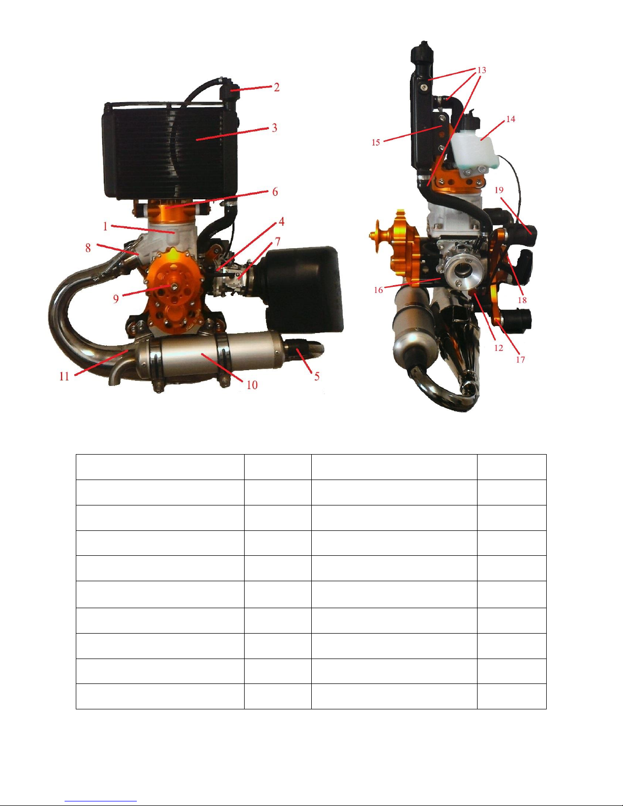
3.1 FIGURE OF THE ENGINE
1: CYLINDER
SK006
11: MUFFLER
SK033
2: RADIATOR CAP
SK013
12: IGNITION COIL
SK040
3: RADIATOR
SK010
13: RADIATOR’S HOSES
SK011/012
4: LAMINAR BUNDLE
SK021/24/26
14: DRAIN RESERVOIR
SK014
5: MUFFLER SEAL
SK043
15: RADIATOR RODS
SK017
6: HEAD + COVER
SK007/08
16: GUARD
SK001
7: WALBRO CARBURETOR
SK019
17: SPIDER
SK032
8: MUFFLER MAINFOLD
SK045
18: MANUAL STARTER
SK036
9: REDUCTION GEAR
SK031
19: SILENT BLOCK
SK015/016
10: SILENCER
SK041

3.2 TECHNICAL SPECIFICATION
TYPE
SINGLE-CYLINDER 2 STAGE ENGINE WITH LIQUID
COOLING
SWEPT VOLUME:
110 CC
MAX POWER
26 HP @ 11200 RPM
MAX. RATED
SPEED:
11300 RPM
BORE
53 mm
STROKE
50 mm
REDUCTION
MECHANICAL 1:4 OIL LUBRICATED
THRUST:
68/70 Kg WITH TWO PROPELLERS IN WOOD 125 cm
@11200 RPM *
70/73 Kg WITH THREE PROPELLERS FROM 125 cm
@10900 RPM*
CARBURETOR
WALBRO WG8
TOTAL WEIGHT:
WITH LIQUIDS 13,5 Kg
EGT:
660 °C
CHT:
170°C
MAX COOLANT
TEMPERATURE:
95°C
MAXIMUM
CAPACITY:
MAXIMUM WEIGHT OF USER: 90-120 Kg
CLUTCH
DRY CENTRIFUGAL
* Test was made in optimal conditions at sea level after running –in
WARNINGS!
The general recommendations included in the Technical Specifications sections are very important
to prevent severe damage to the engine and for the safety of users. ALWAYS FOLLOW THE
INSTRUCTIONS GIVEN ABOVE AND DO NOT EXCEED THE MAXIMUM VALUES SPECIFIED.
SKY ENGINES SHALL NOT BE LIABLE FOR INJURIES TO PEOPLE OR DAMAGES TO
PROPERTY ARISING FROM THE FAILURE TO FOLLOW THE AFOREMENTIONED
TECHNICAL SPECIFICATIONS.
3.3 ASSEMBLY OF SECONDARY COMPONENTS
3.3.1 SPECIAL ASSEMBLY INSTRUCTIONS
Engine SKY110S is more complex than other models and a greater experience is therefore
required to assemble its components and specifically its internal ones. As the engine is liquid
cooled, the assembly of the components that use the radiator's coolant requires the
implementation of specific tasks that only a skilled mechanics is able to carry out.
Therefore, all users who are not specifically skilled or trained to perform these operations
SHOULD NOT TOUCH THE ENGINE EXCEPT FOR ORDINARY MAINTENANCE
OPERATIONS, WHICH SHOULD BE PERFORMED FOLLOWING THE DETAILED
INSTRUCTIONS SPECIFIED BELOW. DO NOT IMPROVISE OR ATTEMPT TO MAKE
UNAUTHORIZED CHANGES THAT COULD DAMAGE THE ENGINES NOT COVERED BY
WARRANTY.
• Unauthorized changes could make the engine highly unstable!
• Replace the components of the engine with original SKY ENGINES spare parts to guarantee a
reliable operation.
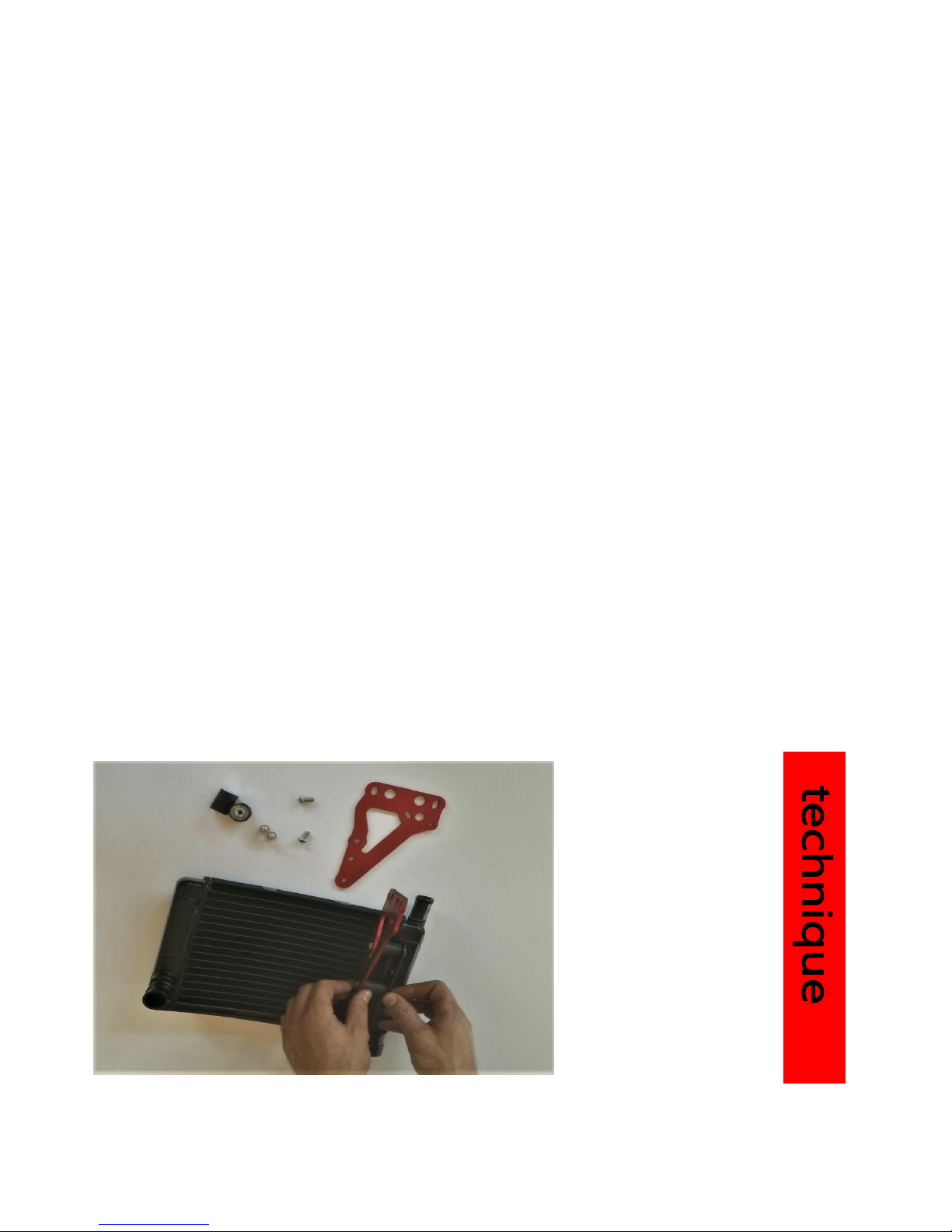
3.3.2 RADIATOR(see also 3.3.3 RODS SILENT-BLOCK)
Mount the special silent blocks on the radiator and then the brackets on the silent blocks
(on both sides).
Then mount the tank as shown.
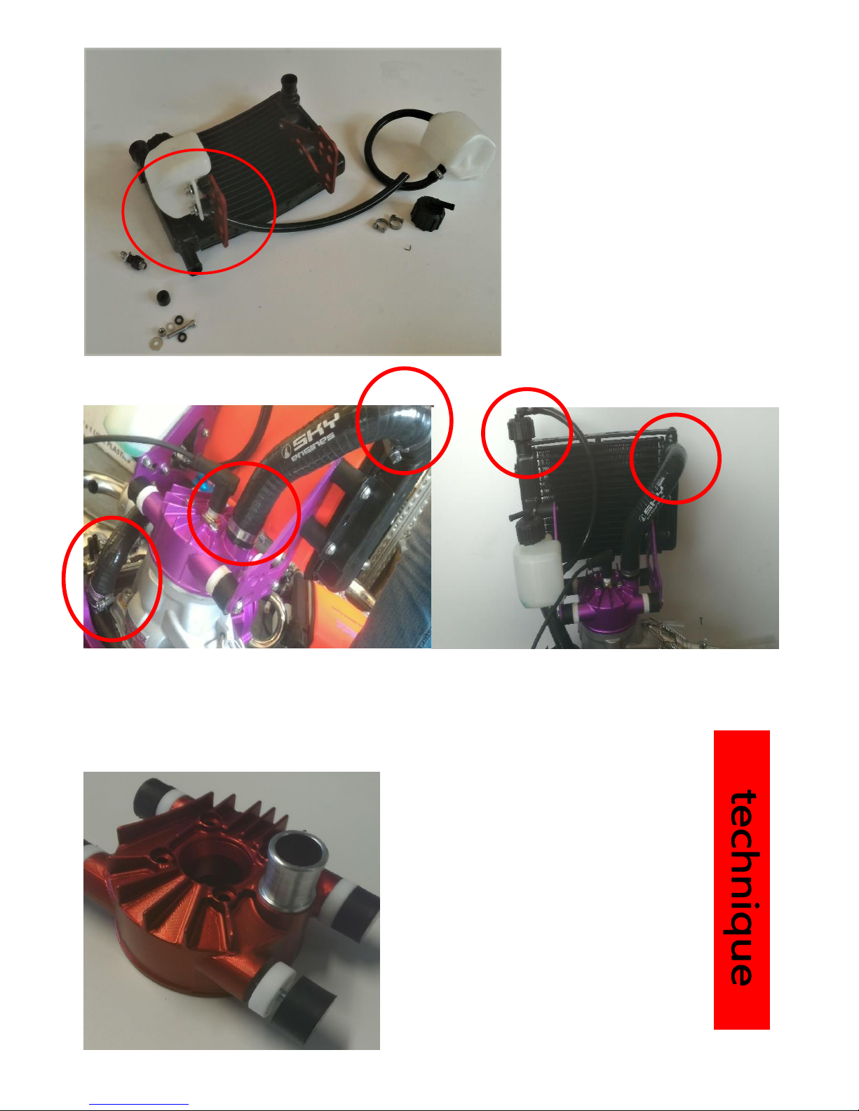
Place the radiator on the cover and
put the tubes in their respective
outlets as shown below.
Check the fitting positions and insert the clamp straps as in the photos.
3.3.3 SILENT BLOCK STAFF.
Fit the teflon plate and then the
silent blocks on the cover as
shown in the figure.

Mount the brackets on the silent block of the
cover and the silent blocks on the brackets.
Place the tank on the bracket and screw the nut without tightening it, just to see the tip of
the screw that goes out as in the figures to the side.
Finally mount the radiator on the silent blocks.

3.3.4 CLUTCH
Before mounting the clutch make sure you have the following pieces.
Place the spring in the seat of the pile and place the clutch body as shown in the figure.
Do this also on the other side.
Place the whole in a vice by helping to fix it from a cylindrical body by matching the holes of
the clamp and clutch body and pushing the pin as shown in the following figure.
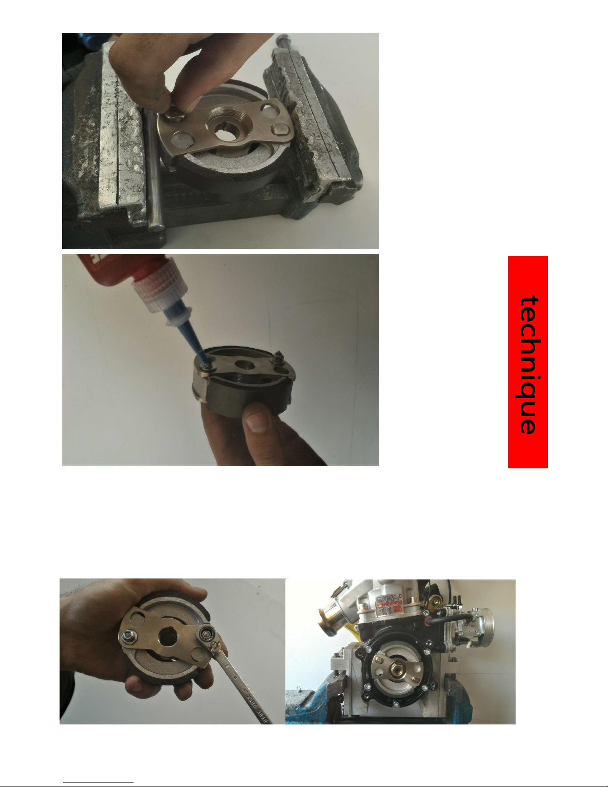
Place the pins on both sides,
also place the washers and
nuts put a loctite handle to
block the threads.
Tighten the nut without tightening the clutch body completely, leaving the relatively free mops in
the picture.
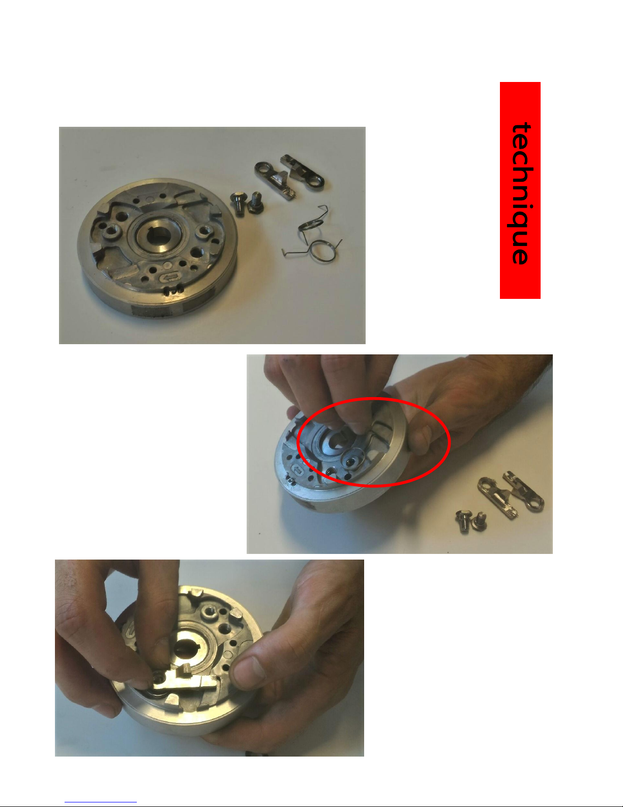
3.3.5 POWER SWITCH
Take the flywheel and make sure it is necessary, ie ratchets, screws and springs.
Be sure to clean the items in question.
Place the spring in the hole and
fly guide as in the photo on the
side.
Place the ratchet and make sure it
engages with the spring.

Place the locking tab and the provided screw, tighten and make sure the ratchet
be free to rotate as in the following 2 photos.
Take the 3.05 mm thick brass
washer (possibly working it)
and place it in the center of
the cup as shown.

Place the spring inside the cup and apply grease to the grease.
Place the rope in the hole in the windshield,
make a small knot to avoid baiting as in the 2
pictures here to the side.

Once you have tightened the winder in the bowl, make 8 ropes of rope to pull
the spring.
Finally, let the rope pass through the bowl hole and get the figure below and make sure it works.
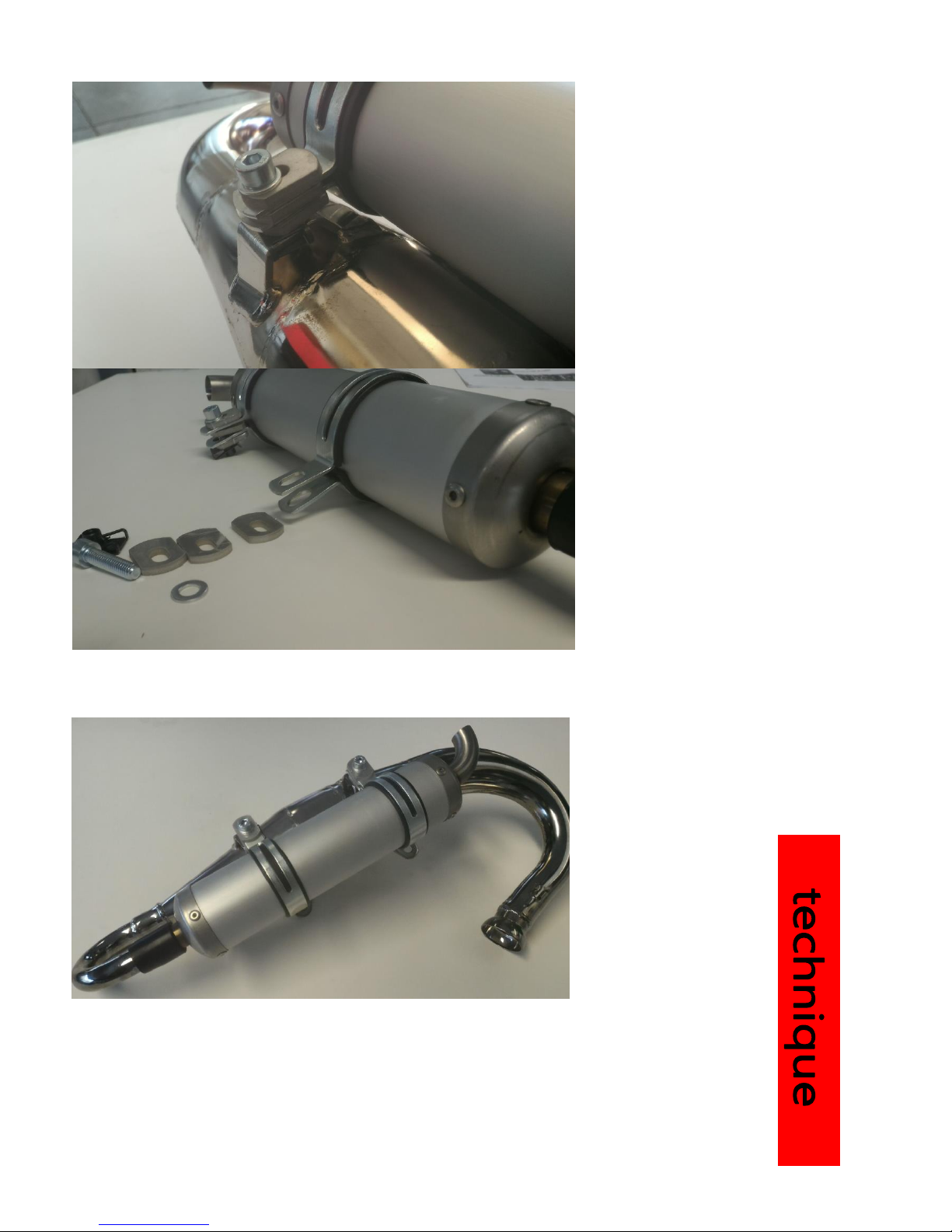
3.3.3 MUFFLER
Mount the 3 washers bend over
the bands and sort them as in
the figure.
Complete the muffler as shown in the figure
Apply copper grease to the inner rim of the muffler manifold, then place
the muffler on the manifold at the glue, pushing the manifold on the manifold
as in the following figures.
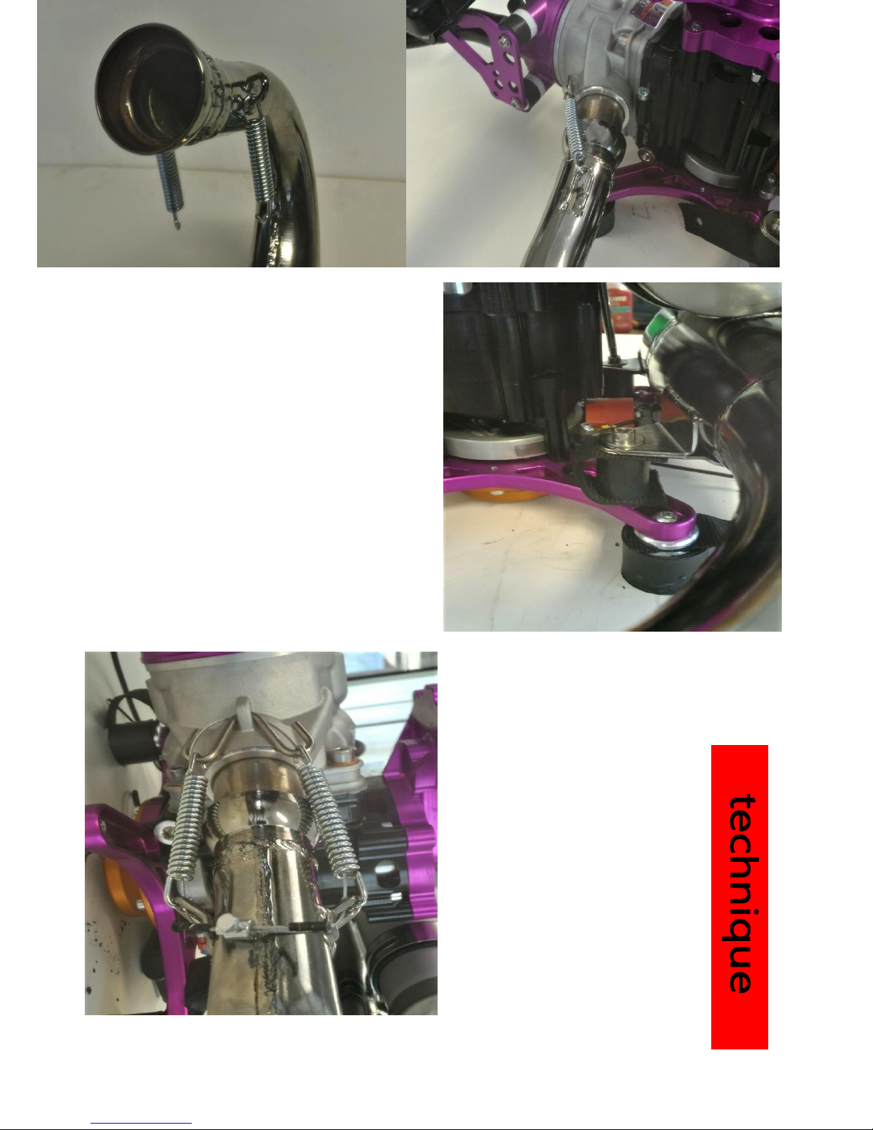
Tighten with 2 screws M6 x 12 and washers
the muffler fittings with silent blocks of the
engine chassis;
place 2 straps between the silent blocks and
the muffler as in the side photo.
Finally, insert the steel cable
between the hooks by sliding it into
the springs and tie it to the
manifold side as in
the picture below.
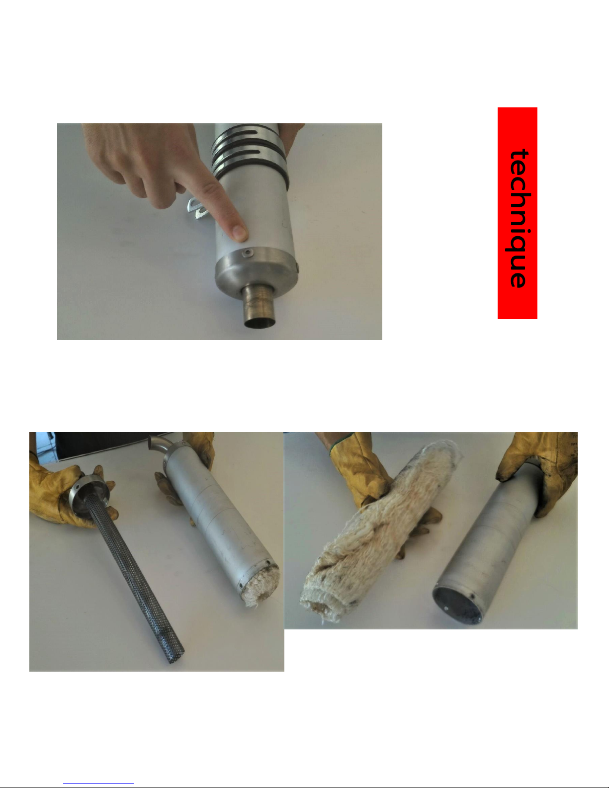
3.3.7 SILENCER
Unscrew the bolts that connect the manifold to the base of the silencer.
Unhook the tube base and remove the tube by holding the silencer out of the socket;
then remove the worn glass wool.
Hook the new glass wool, roll it up, recirculate the tube and screw down the manifold as
shown in the following pictures.
Table of contents
Other SKY Engines Engine manuals


Popular Engine manuals by other brands

Universal
Universal M3-20B Service manual

SOMFY
SOMFY BAT-R Programming instructions

Briggs & Stratton
Briggs & Stratton Vanguard 290000 Operator's manual

nord
nord B 1050 Manual with installation instructions

Leadshine
Leadshine iSV-B23 Series Hardware installation manual

Chery
Chery SQR372 Maintenance manual


