Sky Master 8001R Guide
TM
GARED
PERFORMANCE
SPORTS SYSTEMS
Gared Holdings, LLC
9200 E. 146th St.
Nobles ille, IN 46060
FILE LOC.
SHT. NO. PART NO. REV
Model: 8001 and 8001R
Skymaster Volleyball System
1
OF 27
601756161 C
Q:\Inventor Files\Installation Instructions\Installation Manual
Views\Volleyball\Sky aster III
DATE
1/31/2017
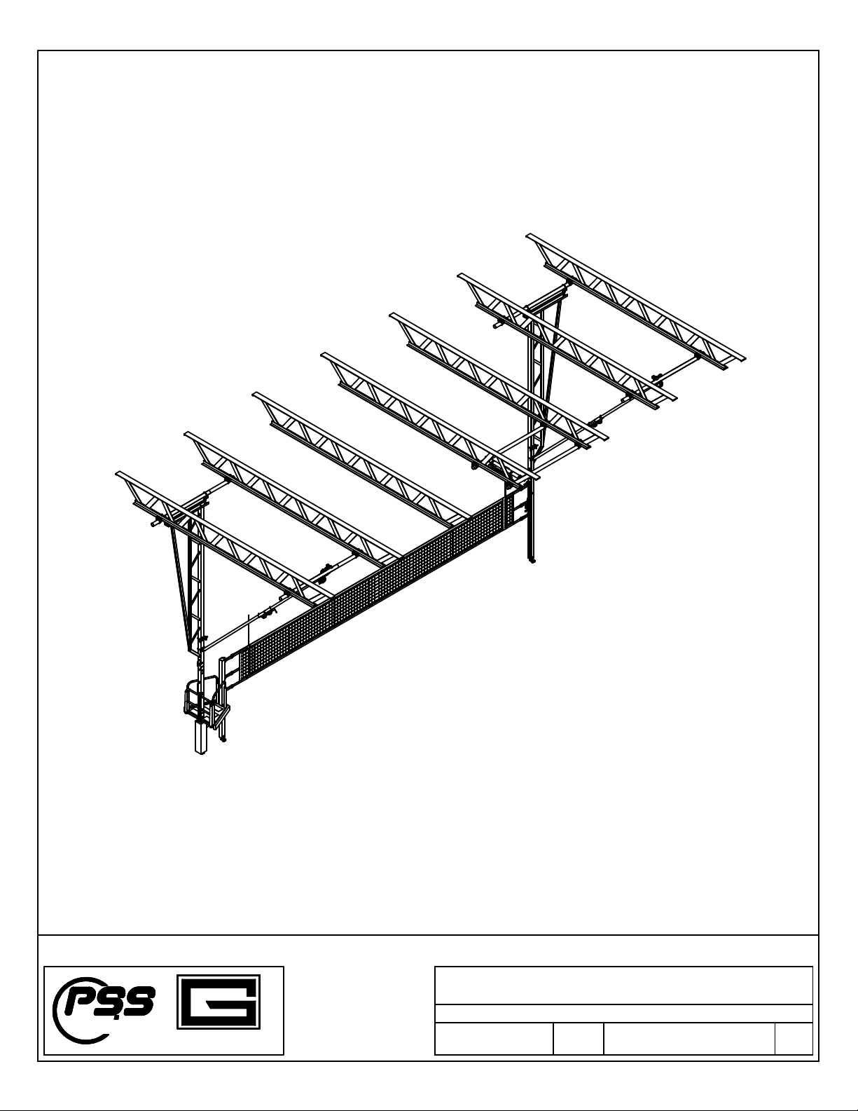
Installation and Assembly Instructions
Skymaster® Volleyball System
Please read & understand all instructions before attempting installation or operation of these units.
Table of C ontents
Section Page N o.
Introduction 2
Tools Required 3
Parts C ecklist 4-6
Installation and Setup 6-13
Referee Stand Pad Installation 14-15
Net Installation D etail 16-19
Electrical & W iring Inform ation 20-22
Operating Instructions 23-24
M aintenance 25-27
Introduction
T ank you for your purc ase of a Skymaster® Volleyball System. To ensure t at our equipment
will provide years of use to you, we are including t is installation, operation, and maintenance
guide. T is guide will provide information on t e proper assembly and installation met ods,
operating procedures, and preventative maintenance of your ceiling suspended volleyball system.
Please note t at a Bill of Materials is being included wit t is guide. Please c eck t at all of t e
parts called out on t e Bill of Materials are present prior to beginning assembly and setup.
Please do not substitute for factory parts. Please contact t e manufacturer’s customer service
department and allow t em to determine if substitute parts are acceptable.
It is recommended t at an individual w o as been properly trained perform assembly and set up
of t e volleyball system. No one under t e age of 18 s ould attempt assembly or set up of t e
unit, unless properly supervised.
To prevent normal wear and tear from s ortening t e life of t e unit, preventative maintenance
inspections and repairs s ould be performed at least once per year. If t e units are subject to
ig or unusual usage, inspections s ould be sc eduled to occur more frequently. If items are
found to be nonconforming, replacements can be ordered from t e manufacturer or one of its
aut orized dealers. W en contacting t e manufacturer or dealer, please ave information
regarding t e dealer/installer w o sold t e unit, t e name of t e project, and any applicable
warranty information.
Before proceeding with assembly, read all instructions and assembly procedures. Ma e sure
all parts have been received and are not damaged.
SHT. NO. PART NO. REV
2
OF 27
601756161 C
DATE
1/31/2017
Installation and Assembly Instructions
,
Operators Manual, and Maintenance Manual
Ceiling Suspended Volleyball System
SHT. NO. PART NO. REV
3
OF 27
601756161 C
DATE
1/31/2017
Installation and Assembly Instructions
,
Operators Manual, and Maintenance Manual
Ceiling Suspended Volleyball System
Tools Required:
Hammer
3/8” Hand Drill
Drill Bits - 3/16” and 1/2” wit 3/8” S ank
3/8” Ratc et Wrenc wit 1/2” and 9/16” Sockets
1/2” Ratc et Wrenc wit 9/16”, 11/16” and 3/4” Sockets
Wrenc es - 1/2”, 9/16”, 11/16”, 3/4” and 1-5/16"
Torque Wrenc s 5-75 Ft-Lbs. and 31-150 Ft-Lbs.
3/16” Allen Wrenc
4” C-Clamps (2)
4' Level
File ( alf round)
25' Tape Measure
Cable Cutters
Utility Knives
Wire Stripper
Screwdrivers (assorted sizes)
Ratc eting Pulleys
75' Ropes
Wire Nuts
Duct Tape
Block of Wood (for tapping)
Broom
S op Vac
Protective Covering for Floor

8001 8001R
46 1115-30-00 3/8" QUICK LINK 2 2
47 1282-30-00 5/16" UNIVERSALSNAP LINK 1 1
48 223-4-20-16Z SCREW, MACH PAN HD PHIL 1/4-20 UNC X 1 24 24
49 3125-30-00 1/4" CABLE THIMBLE 2 2
50 3225-30-00 1/4" CABLE CLAMP (FORGED CLIP) 4 4
51 501-5-18-16 BOLT, CARRIAGE 5/16-18 UNC X 1 10
52 501-5-18-52 BOLT, CARRIAGE 5/16-18 UNC X 3.25 8
53 502-4-20-14 HEX BOLT, 1/4-20 UNC X 0.875 12
54 502-5-18-12Z HEX BOLT, 5/16-18 UNC X 0.75 8
55 502-5-18-16 HEX BOLT, 5/16-18 UNC X 1 3
56 502-5-18-24Z HEX BOLT, 5/16-18 UNC X 1.5 2 2
57 502-5-18-44 HEX BOLT, 5/16-18 UNC X 2.75 2 2
58 502-6-16-40 HEX BOLT, 3/8-16 UNC X 2.5 2
59 502-6-16-80 HEX BOLT, 3/8-16 UNC X 5 5
60 502-8-13-16 HEX BOLT, 1/2-13 UNC X 1 12 12
61 502-8-13-64 HEX BOLT, 1/2-13 UNC X 4 2 2
62 545-5-18Z HEX NUT, NYLON LOCK 5/16-18 4 5
63 545-6-16Z HEX NUT, NYLON LOCK 3/8-16 3
64 545-8-13 HEX NUT, NYLON LOCK 1/2-13 2 2
65 548-5-18Z HEX NUT, SERRATED FLANGE 5/16-18 20
66 548-6-16 HEX NUT, SERRATED FLANGE 3/8-16 4
67 548-8-13 HEX NUT, SERRATED FLANGE 1/2-13 20 24
68 561-4 FLAT WASHER 1/4 12
69 561-5 FLAT WASHER 5/16 2
70 561-6 FLAT WASHER 3/8 7
71 562-4Z SPLIT LOCK WASHER 1/4 24 36
72 562-5 SPLIT LOCK WASHER 5/16 2
73 571-6-16-16 SELF TAPPING SCREW, 3/8-16 UNC X 1 16 16
74 921041000 ABRASIVE ANTISLIP TAPE (12") 3
75 921041000 ABRASIVE ANTISLIP TAPE (20") 1
QTY
Hardware List
Item Part Number Description
TM
GARED
PERFORMANCE
SPORTS SYSTEMS
Gared Holdings, LLC
9200 E. 146th St.
Nobles ille, IN 46060
FILE LOC.
SHT. NO. PART NO. REV
Model: 8001 and 8001R
Skymaster Volleyball System
4
OF 27
601756161 C
Q:\Inventor Files\Installation Instructions\Installation Manual
Views\Volleyball\Sky aster III
DATE
1/31/2017
Installation and Assembly Instructions
Ceiling Suspended Volleyball System
T e following parts list are inclusive aog all ardware and components to assemble t e Skymaster unit. NOT included
in t ese parts lists are t e ardware and components required to attac t e unit to t e over ead building structure (i.e
beam clamps, structural pipe, etc.) Please refer to your packing list enclosed wit t e s ipment for t ose parts.
Below is a list of t e ardware and quantities are per unit. W en multiple units are to be installed, refer to t e packing
list enclosed wit t e s ipment for total quantities of t ese items s ipped.
Major components list is on t e following page.

8001 8001R
1 601756161 MANUAL - 8001-8001R SKYMASTER III 1 1
2 604401462 8001 VB BRIDGE MAST-ANY HEIGHT 2 2
3 161655628 SWING HANGER ASS'Y, 3.5" EXTENDED 4 4
4 1448-11-08 EYEBOLT ASSEMBLY, 7/8"-9 X 6" 4 4
5 604401465 BRKT, OHVB LIFT 2 2
5a 604406158 HINGE WELDMENT, OHVB BRACE 2 2
6 101051043 U-BOLT, 1/2-13 X 4 X 4.0 SQ 6 6
7 161655633 CLAMP ASS'Y, 3.5 X 2.38 SWING HINGE 2 2
8 161655636 PULLEY HANGER ASSEMBLY, 3.5" 2 2
9 1005-07-00 #5 SWIVEL EYE BLOCK (3-1/2" PULLEY) 2 2
10 2375-04-00PC TUBE,RND,2.375 OD X 0.083 WALL
11 503955559 2.38" ADJ BRACE HINGE ASS'Y W/BRKR 2 2
12 604401471 POST WELDMENT, SKYIII NET 2 1
13 604401472 POST WELDMENT, SKYIII REF STAND 1
14 604401473 POST COVER PLATE 4 4
15 604406190 FOOT ASSY, SPRING LOADED 2 3
17 604401284 SKYMASTER HAND RAIL RH WELDED 1
18 604401316 GUIDE RAIL, OVERHEAD VB (92.0) 2 2
19 604401475 REF STAND FLOOR FRAME WELDMENT 2
20 604401478 SKYMASTER HAND RAIL LH WELDED 1
21 604401479 FLOOR PLATE - 8001R REF STAND 1
22 604406163 LADDER WELDMENT, SKYMASTER 1
23 604406167 BRKT WELDMENT, LADDER HINGE 1
24 604552249 RAIL ASSY, 7200 END POST 1 1
25 604553795 RAIL ASSY, 7200 WINCH , 8' STRAP 1 1
26 3025-30-00 1/4" GALVANIZED AIRCRAFT CABLE-7X19
27 1100 SAFESTOP SAFETY LOCKING STRAP 2 2
28 8194 ELEC HOIST,DBL DRUM 115V 1PH 60HZ W/KEY 1 1
30 101131065 1/2 X 7/8 X 14GA MACHINE BUSHING ZN 12 12
31 604406188 SPACER, SAFSTOP BRKT 2 2
32 701501117 SIDE PLATE, SAFE STRAP BRACKET 4 4
33 101651035 4" PLUG FOR SQUARE TUBE 1
34 604401167 PULL HANDLE 1
35 604406170 LATCH, LADDER 1
36 604401692 STRAP, FOLDING LADDER PULL 1
Major omponents
See Packing List
See Packing List
Item Part Number Description QTY
TM
GARED
PERFORMANCE
SPORTS SYSTEMS
Gared Holdings, LLC
9200 E. 146th St.
Nobles ille, IN 46060
FILE LOC.
SHT. NO. PART NO. REV
Model: 8001 and 8001R
Skymaster Volleyball System
5
OF 27
601756161 C
Q:\Inventor Files\Installation Instructions\Installation Manual
Views\Volleyball\Sky aster III
DATE
1/31/2017
Installation and Assembly Instructions
Ceiling Suspended Volleyball System
T e list of Pads and Accessories are on t e next page.

Installation Instructions
T e following illustrations s ow an overview of t e 8001 Ceiling Suspended Volleyball System
and t e 8001R Ceiling Suspended System wit Referee Stand. See installation prints provided
for all over ead structure details.
8001 8001R
80 601651165 VB NET 7000 SERIES 1 1
81 7607-22-00 NET SIDELINE MARKER 2 2
82 1028-22-00 NET ANTENNA 2 2
83 121971504 LABEL, "MANUFACTERED BY PSS" 1 1
84 124403482 DECAL, SKYMASTER VOLLEYBALL PADS 2 2
85 6251 BUCKLE COVERS SET OF (6) 1 1
86 124651582 WARNING LABEL - WINCH TIGHTENING 1 1
PAD KIT 604406171 604406172
90 884404074 PAD, UPRIGHT WINCH POST 2 1
91 884404075 PAD, REF POST LOWER - 1
92 884404076 PAD, REF POST UPPER - 1
93 884403593 PAD, SKYMASTER REF CROSS TUBE - 1
94 884403588 PAD, SKYMASTER REF STAND RH - 2
95 884404069 PAD, HAND RAIL SKYMASTER - 4
96 884404073 PAD, FOLDING LADDER POST - 1
97 883803594 PAD, FOLDING LADDER - 2
Net and Pads
Item Part Number Description QTY
TM
GARED
PERFORMANCE
SPORTS SYSTEMS
Gared Holdings, LLC
9200 E. 146th St.
Nobles ille, IN 46060
FILE LOC.
SHT. NO. PART NO. REV
Model: 8001 and 8001R
Skymaster Volleyball System
6
OF 27
601756161 C
Q:\Inventor Files\Installation Instructions\Installation Manual
Views\Volleyball\Sky aster III
DATE
1/31/2017
Installation and Assembly Instructions
Ceiling Suspended Volleyball System
36'-1 1/2"
[11.01 m]
SKYMASTER® 8001
30'-0"
[9.14 m]
3'- 3/4"
[0.93 m]
HOIST
WINCH
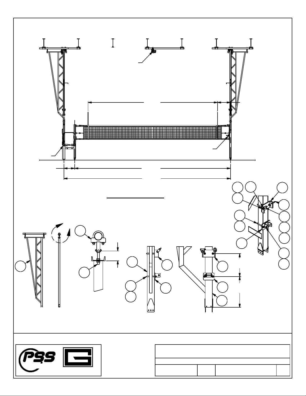
Attachment Details
T ese illustrations s ow some key attac ment details. Use as a guide for proper assembly
SWING HANGER TO
BRIDGE MAST
DETAIL A
BRACE & PULL UP
BRACKET ATTACH
TM
GARED
PERFORMANCE
SPORTS SYSTEMS
Gared Holdings, LLC
9200 E. 146th St.
Nobles ille, IN 46060
FILE LOC.
SHT. NO. PART NO. REV
Model: 8001 and 8001R
Skymaster Volleyball System
7
OF 27
601756161 C
Q:\Inventor Files\Installation Instructions\Installation Manual
Views\Volleyball\Sky aster III
DATE
1/31/2017
Installation and Assembly Instructions
A
Ceiling Suspended Volleyball System
36'-1 1/2"
[11.01 m]
38'-7 1/2"
[11.77 m]
SKYMASTER® 8001R
2
4
3
5a
1'-5"
[433 mm]
1'- 3/4"
[324 mm]
31
31
62
56
62
5
5a
61
64
6
67
2
2
30'-0"
[9.14 m]
COURT
3'- 1/4"
[0.92 m]
WINCH
REF. STAND
HOIST
2'-6"
[762 mm]
0'-4 3/8"
[111 mm]
5
32
46
5
5a
6
67

PULLEY HANGER AND UPPER
FOLDING BRACE BRACKET
TM
GARED
PERFORMANCE
SPORTS SYSTEMS
Gared Holdings, LLC
9200 E. 146th St.
Nobles ille, IN 46060
FILE LOC.
SHT. NO. PART NO. REV
Model: 8001 and 8001R
Skymaster Volleyball System
8
OF 27
601756161 C
Q:\Inventor Files\Installation Instructions\Installation Manual
Views\Volleyball\Sky aster III
DATE
1/31/2017
Installation and Assembly Instructions
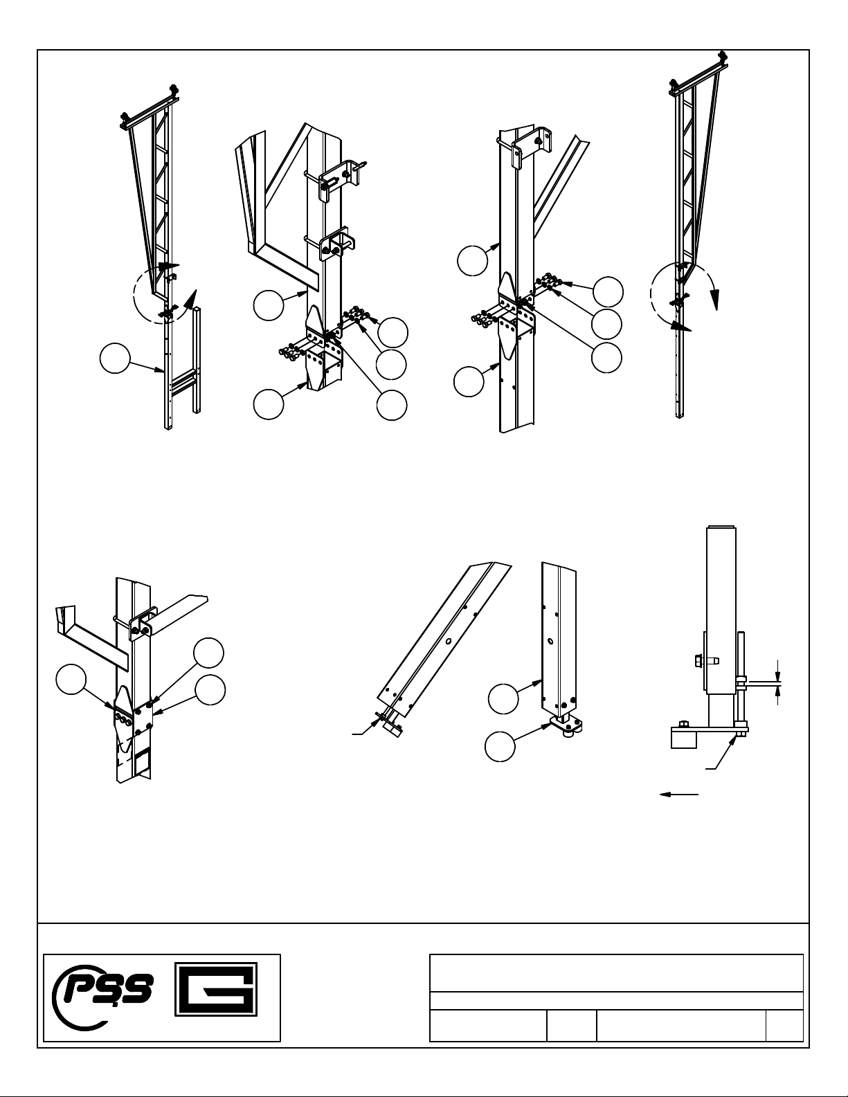
B
C
D
Ceiling Suspended Volleyball System
9
8
7
0'-3 3/4"
[97 mm]
Centerline of bracket
to be in line wit t e
centerline of t e 4"
square mast Pulley anger to be on t e
net side of t e mast centerline
FOLDING BRACE INSTALLATION
10
11
10
REFER TO INSTALLATION
PRINTS WITH SHIPMENT
INSTALL HINGE ASSEMBLY WITH
BREAKER BAR ON NET SIDE OF MAST
AFTER THE BRACE PIPES ARE BOLTED TO THE MAST AND THE CLAMP, SLIDE THE HINGE ASSEMBLY
ONTO THE FREE ENDS OF THE BRACE PIPES. PLUMB THE MAST AND TIGHTEN THE SET SCREWS ON
THE HINGE ASSEMBLY.
61 64
1/2-13 X 3
1
2
HEX BOLT
AND NYLON NUT ARE
SUPPLIED WITH CLAMP
ASSY.
BOLTS, NUTS, AND
SETSCREWS ARE
SUPPLIED WITH
HINGE ASSY.
9
7
8
5a
10
2
7
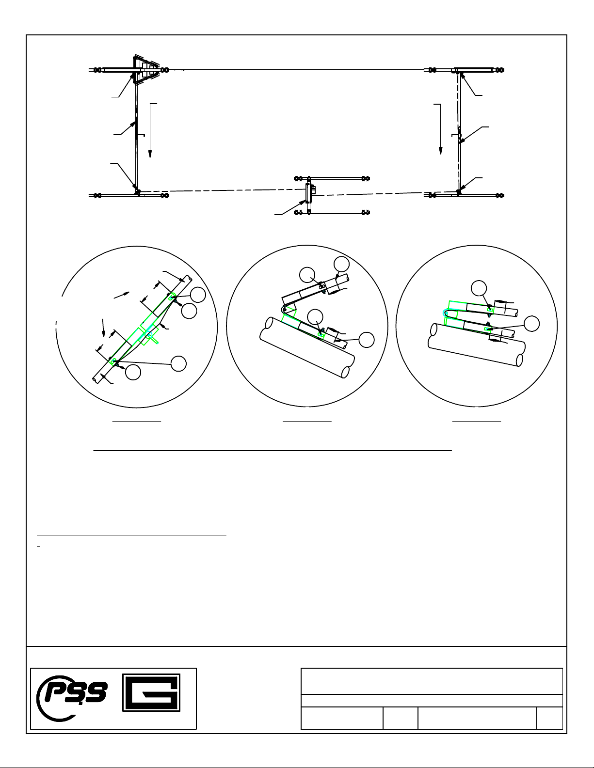
CABLE ROUTING DIAGRAM - PLAN VIEW
TM
GARED
PERFORMANCE
SPORTS SYSTEMS
Gared Holdings, LLC
9200 E. 146th St.
Nobles ille, IN 46060
FILE LOC.
SHT. NO. PART NO. REV
Model: 8001 and 8001R
Skymaster Volleyball System
9
OF 27
601756161 C
Q:\Inventor Files\Installation Instructions\Installation Manual
Views\Volleyball\Sky aster III
DATE
1/31/2017
Installation and Assembly Instructions
UPPER BRACE
LOWER BRACE
STRAP
MAST
MAST
A
H
A
H
D
C
D
C
F
F
A.) ASSEMBLE BRACE PER PRINT AND TIGHTEN
SET SCREWS. (SEE DETAIL 1)
B.) FOLLOW CABLE INSTALLATION
INSTRUCTIONS ABOVE
DO NOT ATTACH CABLE TO HINGE.
C.) FOLD MAST UNTIL HINGE CONTACTS
THE MAST AND STOP. MARK THE BRACE
PIPES 3" ABOVE AND 3" BELOW THE HINGE.
(SEE DETAIL 2)
D.) LOOSEN SET SCREWS AND RAISE THE
MAST TO THE MAXIMUM HEIGHT POSSIBLE.
E.) ADJUST HINGE SO THAT THE "A" + "B" = 6"
EXACTLY. (SEE DETAIL 3)
F.) TIGHTEN SET SCREWS AND LOWER THE MAST
G.) CYCLE MAST A FEW ADDITIONAL TIMES TO
ENSURE PROPER FOLDING.
H.) AS THE FINAL STEP, SECURE THE HINGE BY
DRILLING THROUGH THE BRACE PIPES AND
INSTALL THE SAFETY STRAP WITH THE
PROVIDED HEX HEAD BOLTS AND NYLOCK
NUTS. (SEE DETAIL 1)
ADJUSTABLE BRACE HINGE INTALLATION INSTRUCTIONS.
DETAIL 1 DETAIL 2 DETAIL 3
EQUAL
EQUAL
3"
3"
"A"
"B"
5.5" MIN - 5.875" MAX
EQUAL WITHIN 0.125"
CABLE
PULLEY
MAST
WINCH
PULLEY
CABLE
MAST
DIRECTION OF PULL DIRECTION OF PULL
Ceiling Suspended Volleyball System
REF STAND POST NET END POST
TM
GARED
PERFORMANCE
SPORTS SYSTEMS
Gared Holdings, LLC
9200 E. 146th St.
Nobles ille, IN 46060
FILE LOC.
SHT. NO. PART NO. REV
Model: 8001 and 8001R
Skymaster Volleyball System
10
OF 27
601756161 C
Q:\Inventor Files\Installation Instructions\Installation Manual
Views\Volleyball\Sky aster III
DATE
1/31/2017
Installation and Assembly Instructions
E
F
Ceiling Suspended Volleyball System
13
Install t e ref stand post and net end post onto t e bridge truss mast as s own above. make sure all bolts are securely
torqued.
14
73
14
Install t e cover plates on bot sides
of t e mast as s own above.
15
12
Install t e spring loaded Foot Assy at t e base of eac post as s own
above using (2) 3/8" Self-Tapping Screws. Wit t e mast plumb to t e
floor, adjust t e 3/8-16 adjusting screw to apply approximately 1/4" of
spring pressure to t e foot.
60
30
67
12
2
60
30
67
13
2
HEIGHT ADJUSTING
SCREW, 3/8-16
0'- 1/4"
[6 mm]
HEIGHT ADJUSTING
SCREW, 3/8-16
DIRECTION
OF FOLD

TM
GARED
PERFORMANCE
SPORTS SYSTEMS
Gared Holdings, LLC
9200 E. 146th St.
Nobles ille, IN 46060
FILE LOC.
SHT. NO. PART NO. REV
Model: 8001 and 8001R
Skymaster Volleyball System
11
OF 27
601756161 C
Q:\Inventor Files\Installation Instructions\Installation Manual
Views\Volleyball\Sky aster III
DATE
1/31/2017
Installation and Assembly Instructions
33
24
18
48
71
25
48
71
18
Always install t e end rail assembly (Item 24)
on t e referee stand post and t e winc rail
assembly (Item 25) on t e post opposite t e
referee stand for proper pad installation and fit.
End Post Assembly
Winc Post Assembly
Ceiling Suspended Volleyball System
8001R Referee Stand to Mast Assembly Details
See views on t e following page
Install t e two referee stand floor frames (Item 19) onto eac side of t e referee stand frame. Note t at only t e rear
of t e frames (slotted ole end) require flat was ers under t e bolt ead and under t e nuts.
12
13

TM
GARED
PERFORMANCE
SPORTS SYSTEMS
Gared Holdings, LLC
9200 E. 146th St.
Nobles ille, IN 46060
FILE LOC.
SHT. NO. PART NO. REV
Model: 8001 and 8001R
Skymaster Volleyball System
12
OF 27
601756161 C
Q:\Inventor Files\Installation Instructions\Installation Manual
Views\Volleyball\Sky aster III
DATE
1/31/2017
Installation and Assembly Instructions
Ceiling Suspended Volleyball System
66
19
66
70
70
59
19
21
20 17
65
51
65
Install t e floor plate (Item 21) and and rails (Items 17 and 20), T e 5/16" carriage bolts (Item 52) for t e and rail
attac ments are 3 1/4" long and go all t e way t roug t e frame. T e 5/16" carriage bolts (Item 51) are 1" long and
only go t roug t e top flange of t e frame.
Use t e 5/16" w izlock nuts on all bolts and tig ten securely.
Cut t e anti-slip tape (Item 73) into 4 pieces. 3 pieces
12" long and 1 piece 20" long.
Place t e pieces onto t e top surface of t e floor plate
as s own in t e diagram on t e left.
Remove t e backing strip from t e tape and press
t e tape firmly onto t e floor plate making sure t ere are no
air bubbles or wrinkles
52
DETAIL M
LADDER FOLDED
AND LATCHED
DETAIL N
LADDER LATCHED
TM
GARED
PERFORMANCE
SPORTS SYSTEMS
Gared Holdings, LLC
9200 E. 146th St.
Nobles ille, IN 46060
FILE LOC.
SHT. NO. PART NO. REV
Model: 8001 and 8001R
Skymaster Volleyball System
13
OF 27
601756161 C
Q:\Inventor Files\Installation Instructions\Installation Manual
Views\Volleyball\Sky aster III
DATE
1/31/2017
Installation and Assembly Instructions
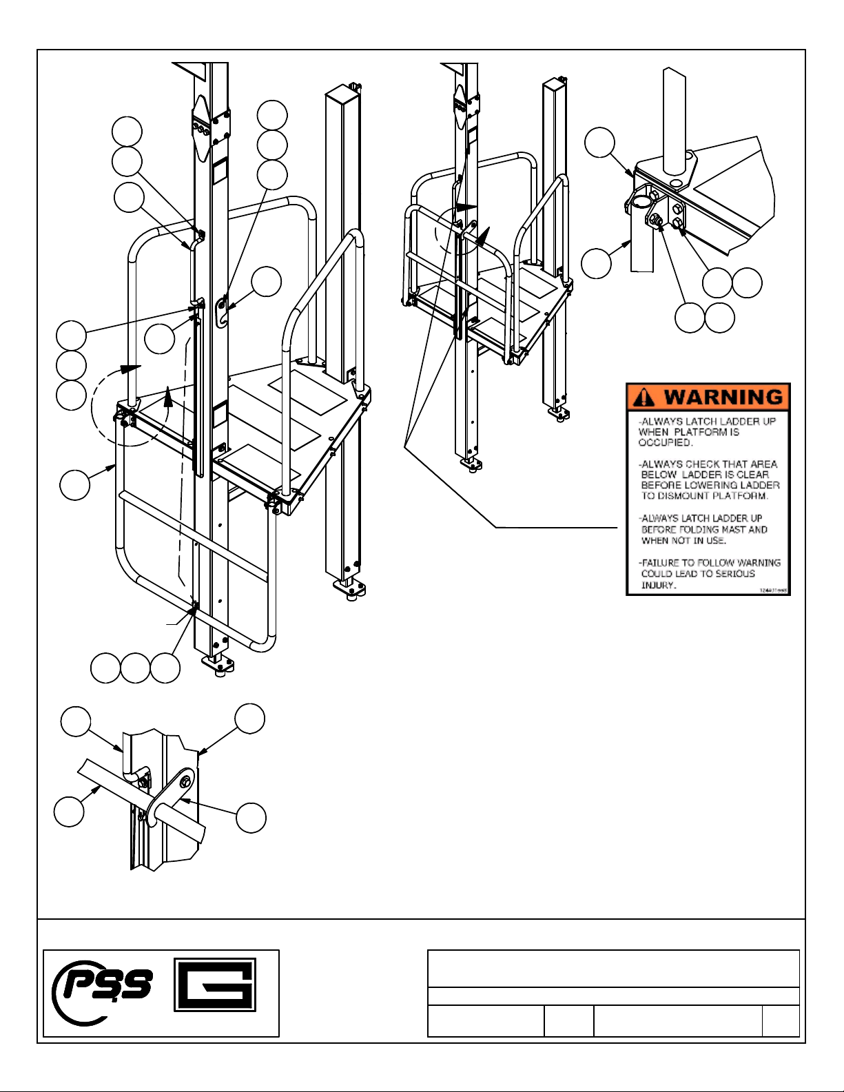
M
N
34
55
72
59
70
63
35 54 65
58 63
22
19
22
Connect the ladder pull
up strap to this bolt
Attached Ladder Brackets to platform frame with 5/16-18 x 3/4"
hex head screws and 5/16"flange nuts.
Attach Ladder Weldment to Ladder Brackets with 5/16-18 x 2
1/2" bolts and 5/16" lock nuts.
Attach the top of the Handle to mast post using 5/16-18 x 1 bolt
and lockwasher. The lower Handle bolt will also anchor the
ladder pull up Strap using a 5/16-18 x 1 bolt, lock washer and
flat washer.
The opposite end of the pull up Strap should be attached to the
Ladder with a 5/16-18 x 1" hex bolt, flat washer and locknut.
Attach the Ladder Locking Bracket to the Mast post using
3/8-16 x 5" hex bolt, flat washer and locking nut. The Locking
Bracket bolt should only be snugged so that Bracket swings
freely.
55
6962
55
72
69
36
35
22
34 13
-

8001R shown
8001 will use (2) Upright Post Pads (Item 90). DETAIL P
TM
GARED
PERFORMANCE
SPORTS SYSTEMS
Gared Holdings, LLC
9200 E. 146th St.
Nobles ille, IN 46060
FILE LOC.
SHT. NO. PART NO. REV
Model: 8001 and 8001R
Skymaster Volleyball System
14
OF 27
601756161 C
Q:\Inventor Files\Installation Instructions\Installation Manual
Views\Volleyball\Sky aster III
DATE
1/31/2017
Installation and Assembly Instructions
P
Ceiling Suspended Volleyball System
SKYMASTER PAD INSTALLATION
1. Install t e frame pads (Item 94) to t e frame rails using t e 1/4" x 7/8" ex
bolts (Item 53), 1/4" flat was er (Item 68) and 1/4" lockwas er (Item 71). A
quantity of (6) are required for eac pad.
2. Install t e and rail pads (Item 95) to t e (4) vertical and tubes.
3. Install t e ladder rail pad (Item 97) to t e vertical ladder tubes.
4. Install t e main post pad (Item 96) to t e post and secure wit velro straps.
5. Install t e crossover tube pad (Item 93) to t e lower orizontal rectangular
tube of t e referee stand frame and secure wit t e velcro straps.
6. Install ref stand net post pads (Item 91 & 92) to t e net post
7. Install t e winc post pad (Item 90) to t e winc post. On model 8001,
wit out ref stand, t ere will be a (Item 90) pad to install on bot t e winc
post and t e end post.
91
92
93
96
97
95
94
95
90
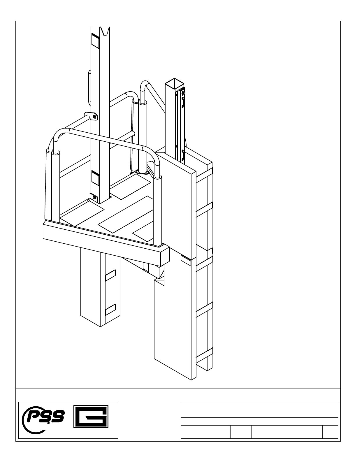
Referee Stand Pads Installed
TM
GARED
PERFORMANCE
SPORTS SYSTEMS
Gared Holdings, LLC
9200 E. 146th St.
Nobles ille, IN 46060
FILE LOC.
SHT. NO. PART NO. REV
Model: 8001 and 8001R
Skymaster Volleyball System
15
OF 27
601756161 C
Q:\Inventor Files\Installation Instructions\Installation Manual
Views\Volleyball\Sky aster III
DATE
1/31/2017
Installation and Assembly Instructions
Ceiling Suspended Volleyball System

N et In stalla tion Instru ctions
1. U nfold t e net and la y it out betw een t e tw o posts.
2. T e eig t of t e net is set by adjusting t e eig t of t e slide rails on t e en d post and w inc
post. R elease t e ca m loc s on t e rails and set t e net cable attac m ent points approx im ately
3/4” ig er t an t e desired pla yin g eig t (w ic is m easured at t e center of t e court). R eset
t e cam locks.
3. A ttac one end o f t e tension cable to t e ook at t e top of t e en d post ra il as s ow n. N ext
rotate t e crank and le of t e w inc co unter-
clockw ise to extend t e belt. A ttac t e ot er end of
t e cable to t e belt of t e w inch post rail w it a snap link. T urn t e w inc and le clockw ise to
tig ten t e belt.
4. C enter t e net so t ere is equal space betw een t e ends of t e net and t e posts. U ndo t e
V elcro net straps as t ey com e s ipped w it t e net.
W rap t e strap s t roug t e footm an’s loops
as s ow n in t e illustration at t e bottom of t is page. Pull t e straps tig t and press t e V elcro
surfaces toget er. T ese straps are responsib le fo r m aintaining t e net tension and m ay need to
be retig tened p eriodically. E x pect stretc in t e n et. In stall t e buckle pad s.
5. T e eig t of t e net w ill vary slig tly w it t e tig tness of t e cable. If t e net eig t needs
to be adjusted , loosen net strap s and loosen t e cable to take p ressu re o ff of t e side rails.
R elease t e cam lock s and m ove t e rails to t e desired eig t. T ig ten t e cam locks and
retig ten t e net.
R efer to t e illustrations on t e follo w ing pages fo r pro per net strap installation and position.
SHT. NO. PART NO. REV
16
OF 27
601756161 C
DATE
1/31/2017
Installation and Assembly Instructions
,
Operators Manual, and Maintenance Manual
FINISHED FLOOR
Ceiling Suspended Volleyball System
TABLE
VB Type US Di s Metric Di s
Men's VB 95 5/8" [2.429 ]
Wo en's VB 88 1/8" [2.238 ]
Youth VB 84" [2.134 }
Girl's VB 78" [1.981 ]
IMPORTANT:
DO NOT OVERTIGHTEN THE NET CABLE.
DO NOT TENSION THE NET CABLE IN THE
COUNTERCLOCKWISE DIRECTION.
30'-0"
[9.14 m]
COURT WIDTH
8'-3/8"
[2448 mm]
Maximum
7'-11 5/8"
[2428 mm]
MEN'S HEIGHT
AT CENTER LINE
8'-3/8"
[2448 mm]
Maximum
Centerline of Court

SHT. NO. PART NO. REV
17
OF 27
601756161 C
DATE
1/31/2017
Installation and Assembly Instructions
,
Operators Manual, and Maintenance Manual
Ceiling Suspended Volleyball System
MAST
PULL STRAP TIGHT AND
PRESS VELCRO PADS
TOGETHER
THREAD STRAP THROUGH
RECTANGULAR STEEL RING
NET
(ADJUST BUCKLE TO THIS
APPROXIMATE POSITION)
THREAD STRAP THROUGH
FOOTMANS LOOP
Footman's Loop
Net Strap
TOP VIEWS OF NET STRAP PLACEMENT
STEP 1
STEP 2
STEP 3
CONNECTION AT END POST (REFEREE STAND END) OF THE NET°
CONNECTION AT WINCH POST END OF THE NET
(ADJUST BUCKLE TO THIS
APPROXIMATE LOCATION)
STEP 1
STEP 2
STEP 3
THREAD STRAP THROUGH
FOOTMANS LOOP(S)
THREAD STRAP THROUGH
RECTANGULAR STEEL RING
PULL STRAP TIGHT AND
PRESS VELCRO PADS
TOGETHER
TOP AND CENTER STRAP MUST PASS
THROUGH TWO (2) FOOTMANS LOOPS
BOTTOM STRAP PASSES THROUGH
ONLY ONE (1) FOOTMANS LOOP
MAST
NET

TM
GARED
PERFORMANCE
SPORTS SYSTEMS
Gared Holdings, LLC
9200 E. 146th St.
Nobles ille, IN 46060
FILE LOC.
SHT. NO. PART NO. REV
Model: 8001 and 8001R
Skymaster Volleyball System
18
OF 27
601756161 C
Q:\Inventor Files\Installation Instructions\Installation Manual
Views\Volleyball\Sky aster III
DATE
1/31/2017
Installation and Assembly Instructions
Ceiling Suspended Volleyball System
Net Installation - End Post Details
NET ATTACHMENT SAME WITH
OR WITHOUT REFEREE STAND
PADS NOT SHOWN FOR CLARITY
GUIDE RAIL EXTRUSION
WRAP NET STRAP THROUGH
FOOTMANS LOOP
(SEE SHEET 17)
CAM LOCK
HEIGHT ADJUSTMENT RAIL
WRAP NET STRAP THROUGH
FOOTMANS LOOP
(SEE SHEET 17)
INSTALL BUCKLE COVERS (ITEM 85)
P/N 6251 OVER METAL RINGS
NET CABLE
WRAP NET STRAP THROUGH
FOOTMANS LOOP
(SEE SHEET 17)

TM
GARED
PERFORMANCE
SPORTS SYSTEMS
Gared Holdings, LLC
9200 E. 146th St.
Nobles ille, IN 46060
FILE LOC.
SHT. NO. PART NO. REV
Model: 8001 and 8001R
Skymaster Volleyball System
19
OF 27
601756161 C
Q:\Inventor Files\Installation Instructions\Installation Manual
Views\Volleyball\Sky aster III
DATE
1/31/2017
Installation and Assembly Instructions
Ceiling Suspended Volleyball System
MAST POST
Net Installation - Winch Post Details
PADS NOT SHOWN FOR CLARITY
SNAP LINK
NET CABLE
INSTALL BUCKLE COVERS (ITEM 85)
P/N 6251 OVER METAL RINGS
WINCH
BELT
SEE NET STRAP DETAILS SHEET 17
RATCHET WINCH
CAM LOCK
HEIGHT ADJUSTMENT RAIL
GUIDE RAIL EXTRUSION
WRAP NET STRAP THROUGH
FOOTMANS LOOP
(SEE SHEET 16)
1'-10"
[559 mm]
-
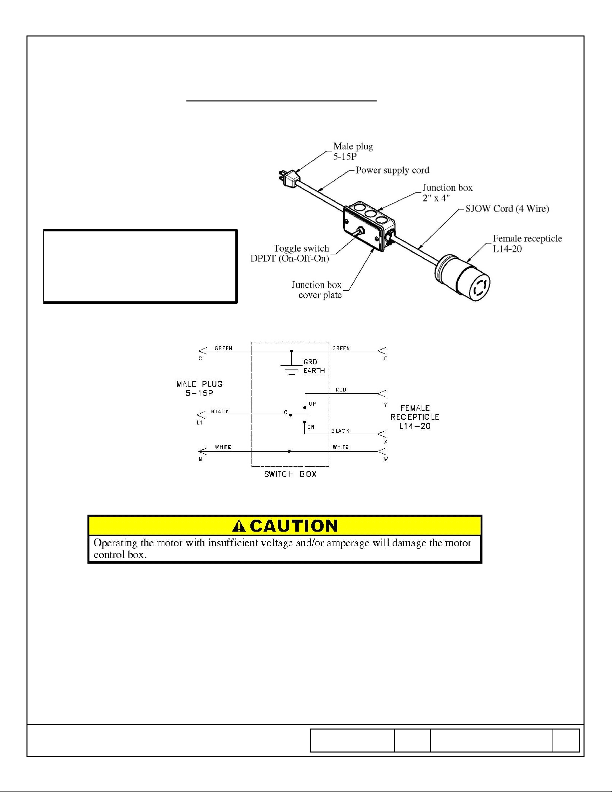
Electrical Wiring an
d Limit Switches
Most installations will require temporary wiring to be connected for power to set t e motor limits and test
t e curtain. Permanent wiring will be installed later by t e electrical contractor.
For temporary power to t e motor, a test
cord as s own can be manufactured
locally or purc ased from t e factory. In
order to provide t e required voltage and
amperage to t e motor, t e cord must meet
t e required wire sizes for t e specified
distance.
Extension cord for testing must be 16-3 or
eavier up to 25 feet run, 14-3 or eavier
for 25 to 50 feet run, 12-3 or eavier for
50 to 90 feet run, and 10-3 or eavier for
90 to 140 feet runs.
Test Cord Schematic
Damage caused due to inadequate electrical supply will not be covered under warranty.
SHT. NO. PART NO. REV
20
OF 27
601756161 C
DATE
1/31/2017
Installation and Assembly Instructions
,
Operators Manual, and Maintenance Manual
Before connecting t e temporary power and attempting to set t e limit switc es, make sure t ere are no
obstructions in t e way of t e masts or net w en folding.
Make sure t ere are no personnel near or under t e masts w en folding.
Ceiling Suspended Volleyball System
This manual suits for next models
1
Table of contents
Popular Accessories manuals by other brands


Merkury Innovations
Merkury Innovations Smart Wi-Fi Essential Oil Diffuser Start guide

Prime
Prime SmartOutlets RCWFIO instruction manual

Fike
Fike FIK-2351TIR Installation and maintenance instructions

WATTECO
WATTECO Vaqa'O quick start guide

Babolat
Babolat PULSE user guide

EVERSPRING
EVERSPRING SP818 user manual