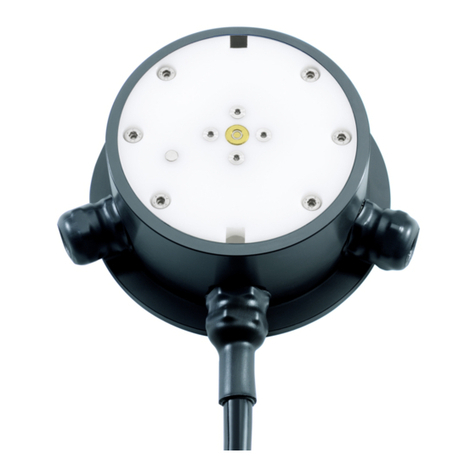
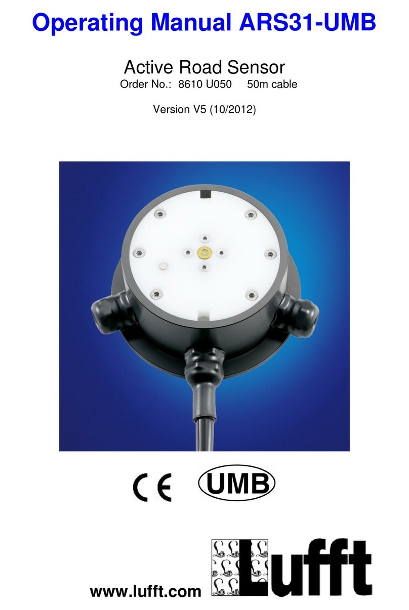
Lufft ARS31Pro-UMB User manual

Operating Manual
ARS31Pro-UMB
ARS31-UMB
Active Road Sensor
Order No. ARS31Pro-UMB: 8810.U051 50m cable
Order No. ARS31-UMB: 8610.U050 50m cable
Version V6 (06/2014)

Operating Manual ARS31Pro-UMB English
© G. Lufft Mess- und Regeltechnik GmbH, Fellbach, Germany. Subject to change without notice. 2

ARS31(Pro)-UMB Operating Manual V9/03.2017
G. Lufft Mess- und Regeltechnik GmbH, Fellbach, Germany 3
Contents
1Please read before commissioning ........................................................................................................5
1.1 Symbols used.....................................................................................................................................5
1.2 Safety instructions ..............................................................................................................................5
1.3 Designated use...................................................................................................................................5
1.4 Guarantee...........................................................................................................................................5
1.5 Incorrect use.......................................................................................................................................5
1.6 Nomenclature .....................................................................................................................................5
2Order Numbers.......................................................................................................................................6
2.1 Accessories ........................................................................................................................................6
2.2 Additional Documents and Software ..................................................................................................6
3Differences between ARS31Pro-UMB/ARS31-UMB..............................................................................7
4Device description ..................................................................................................................................8
4.1 Method of operation ARS31Pro-UMB/ARS31-UMB...........................................................................8
4.2 Additional features of ARS31Pro-UMB...............................................................................................9
4.3 Availability of measurement values ....................................................................................................9
5Installation.............................................................................................................................................10
5.1 Preparation.......................................................................................................................................10
5.2 Installation.........................................................................................................................................10
5.3 Connecting the cable........................................................................................................................14
5.4 Commissioning and testing ..............................................................................................................18
6Maintenance.........................................................................................................................................19
6.1 Replacing the sensor system ...........................................................................................................19
6.2 Connections......................................................................................................................................20
7Configuration ........................................................................................................................................22
7.1 Factory settings ................................................................................................................................22
7.2 Using PC configuration software......................................................................................................22
7.3 Firmware update...............................................................................................................................26
8Communication.....................................................................................................................................27
8.1 Binary protocol..................................................................................................................................27
8.2 ASCII protocol...................................................................................................................................29
8.3 Channel assignment for the data request ........................................................................................30
8.4 Mapping standards...........................................................................................................................32
9Technical data ......................................................................................................................................33
9.1 Measurements..................................................................................................................................33
9.2 Storage conditions (complete sensor)..............................................................................................33
9.3 Operating conditions.........................................................................................................................34
9.4 Electrical data...................................................................................................................................34
9.5Interfaces..........................................................................................................................................34
9.6 Mechanical data (excluding cable) ...................................................................................................34
10 EC Certificate of Conformity.................................................................................................................35
11 Troubleshooting....................................................................................................................................36
12 Service and maintenance.....................................................................................................................37
13 Disposal................................................................................................................................................37
14 Manufacturer.........................................................................................................................................38
14.1 Technical support .............................................................................................................................38
15 List of Figures.......................................................................................................................................39
ARS31(Pro)-UMB Operating Manual V9/03.2017
G. Lufft Mess- und Regeltechnik GmbH, Fellbach, Germany 4
Version history:
Version
Date
Edited by
Comments
1
21.08.2012
LA/BR/FS
First version
2
17.09.2012
LA/BR/FS
Technical data modified, adjustment to current public standards
3
10.04.2013
FS
Supplements to the cable length and to the installation
4
18.04.2013
FS
Extension cable table was added
5
12.03.2014
LA/BR/RR
Modification of Certificate of Conformity, clarification of the technical data (freezing temperature)
6
04.06.2014
LA/BR
Supplements to the cable length and power supply, integration of ARS31-UMB
7
10.07.2015
LA/BR
Calculation of saline concentration according to CEN/TC 15518-4, figures and channels updated
8
14.03.2016
LA
Technical data modified
9
16.03.2017
LA/BR
Technical data modified, chapter 7.3 updated

ARS31(Pro)-UMB Operating Manual V9/03.2017
G. Lufft Mess- und Regeltechnik GmbH, Fellbach, Germany 5
1 Please read before commissioning
Before using the equipment, please read the operating manual carefully and follow the
instructions in every detail.
This operating manual covers ARS31Pro-UMB/ARS31-UMB device version 9 and above
and firmware 10.3 and above.
1.1 Symbols used
Important indication concerning possible hazards to the user
Important indication for the correct functioning of the equipment
1.2 Safety instructions
Installation and commissioning must only be carried out by suitably qualified specialist
personnel.
Never take measurements on or touch live electrical parts.
Pay attention to the technical data and storage and operating conditions.
1.3 Designated use
The equipment must only be operated within the range of the specified technical data.
The equipment must only be used under the conditions and for the purposes for which
it was designed.
The safety and operation of the equipment can no longer be guaranteed if it is modified
or adapted.
Do not continue to use equipment that is obviously defective.
1.4 Guarantee
The guarantee period is 12 months from the date of delivery. The guarantee is forfeited if
the designated use is violated.
1.5 Incorrect use
If the equipment is installed incorrectly
-It may not function
-It may be permanently damaged
If the equipment is not connected correctly
-It may not function
-It may be permanently damaged
-There may be a possibility of an electrical shock
1.6 Nomenclature
Tg: Freezing temperature that the sensor identified
Tu: Road surface temperature, ambient temperature
Toi: Threat of icing

ARS31(Pro)-UMB Operating Manual V9/03.2017
G. Lufft Mess- und Regeltechnik GmbH, Fellbach, Germany 6
2 Order Numbers
ARS31Pro-UMB .. 50 m cable length.................................……. 8810.U051
ARS31-UMB........ 50 m cable length......................................... 8610.U050
2.1 Accessories
Power supply unit 24V/100VA...........8160.UISO
ISOCON-UMB...................................8160.UISO
Surge protection................................8379.USP
DACON8-UMB ..................................8160.UDAC
2.2 Additional Documents and Software
You can download the following documents and software via the Internet at www.lufft.de:
Operating Manual
This document
UMB Config Tool
Windows® software for testing, firmware updates and
configuration of UMB devices
UMB Protocol
Communication protocol for UMB devices
Firmware
The current equipment firmware

ARS31(Pro)-UMB Operating Manual V9/03.2017
G. Lufft Mess- und Regeltechnik GmbH, Fellbach, Germany 7
3 Differences between ARS31Pro-UMB/ARS31-UMB
ARS31Pro-UMB compared with ARS31-UMB possesses the following features:
Measurement of threat of icing by means of a direct measurement or freezing
temperature.
Exact measurement of road surface temperature with an external temperature
sensor.
Figure 1: ARS31Pro-UMB with an external temperature sensor

ARS31(Pro)-UMB Operating Manual V9/03.2017
G. Lufft Mess- und Regeltechnik GmbH, Fellbach, Germany 8
4 Device description
Active Road Sensor ARS31Pro-UMB/ARS31-UMB serves to determine the freezing
temperature of a liquid on the road surface. It can be used to measure the following data:
Salt concentration (NaCl, CaCl and MgCl)
Product concentration (potassium acetate, potassium)
Freezing temperature (independent of mixture)
The sensor excels further due to the following features:
Compact design and easy installation
Low maintenance
Parts can be replaced without uninstalling the device
Data transfer via RS485
Internal electrical isolation of power supply
ESD protection on all interfaces
Inverse-polarity protection
4.1 Method of operation ARS31Pro-UMB/ARS31-UMB
ARS31Pro-UMB/ARS31-UMB determines the freezing temperature of a liquid on the road
surface by means of active cooling and heating. The Sensor allows precise determination
of the freezing temperature in the absence of accurate knowledge of the type or mixture of
salt.
The sensor operates in a temperature range described in the chapter 9.3 Operating
conditions.
The freezing temperature is calculated for road surface temperatures of less than 5°C
(adjustable between 2°C and 10°C). The lowest possible freezing temperature that can be
calculated is about 20°C below the current road surface temperature, for details see
chapter 9.1.1 Freezing temperature.
The sampling rate for freezing point measurement in the sensor is configurable and may
be set to 20, 30 or 60 minutes (factory settings: 20 minutes). If the ambient conditions so
require, the sensor extends its measurement cycle by up to 10 minutes if necessary.
To avoid measurement gaps due to interference during measurement, the sensor is
equipped with an intelligent “hold measurement” function for freezing temperature.
If there is no freezing temperature / salt concentration detected in a measuring cycle the
last identified freezing temperature will be delivered for the following 40 minutes (default:
40 –interval can be adjusted). During this interval the freezing temperature can only move
to 0°C if the sensor definitely detects clear water on the road.
The freezing temperature profile is smoothed by the sensor. This function can be disabled
using the UMB-Config Tool.
Data polling takes place through any desired host computer which supports any of the
communication protocols described in Section 6 and disposes of an RS485 interface.

ARS31(Pro)-UMB Operating Manual V9/03.2017
G. Lufft Mess- und Regeltechnik GmbH, Fellbach, Germany 9
Measurements are polled and transmitted over an RS485 interface.
The device is connected using a 4-core cable.
Windows PC software is available for configuration and measurement polling during
commissioning.
4.2 Additional features of ARS31Pro-UMB
In addition, ARS31Pro-UMB determines the threat of icing as follows: for a dry road –by
cooling to an adjustable temperature value (∆ T1); for a wet road - by comparing the
measured freezing temperature with the road surface temperature while taking account of
the set temperature value (∆ T2).If a threat of icing is determined using one of the methods
described above, the sensor transmits “threat of icing”.“Threat of icing” is only transmitted
as a result of a direct measurement if the road temperature is less than +2°C.
This function must be activated in Configuration of the sensor.
To avoid measurement gaps due to interference during measurement, the sensor is
equipped with an intelligent “hold measurement” function also for threat of icing.
If the condition “threat of icing” was triggered by the freezing temperature measurement
and the freezing temperature enters the hold state, the condition “threat of icing” is also
updated via the last determined freezing temperature and the current road temperature. In
this case, updating of the threat of icing ends simultaneously with the updating of freezing
temperature. However, if during updating the threat of icing is actively determined by
means of a direct measurement, this condition is retained for the set period.
With external sensor the road surface temperature is determined exactly.
4.3 Availability of measurement values
After a successful measurement, the measurement values are available for query until new
measurement values are available. Synchronization between query and measurement
cycle is not needed. It is recommended to poll the sensor every minute. Within the
measurement interval the measured values are immediately updated when they become
available. Due to different environmental conditions the timing of the availability of
measurements can alter in the measurement interval, the measurement values are
therefore not necessarily updated in the grid of the selected measurement interval.
Start measurement
Start measurement
Start measurement
Start
TG 1
availa
ble
TG 2 available
TG 3
availa
ble
0
min
5
min
10
min
15
min
20
min
25
min
30
min
35
min
40
min
45
min
50
min
55
min
60
min
Figure 2: Example: Measurement interval 20 minutes
1) At time 15 min TG 1 is available and will be issued
2) In the next measurement cycle, at the time 25 min GT 2 is determined and issued. So
TG1 was issued for 10 minutes.
3) In the next measurement cycle, at the time 25 min GT 3 determined and issued. So TG2
was issued for 30 minutes.

ARS31(Pro)-UMB Operating Manual V9/03.2017
G. Lufft Mess- und Regeltechnik GmbH, Fellbach, Germany 10
5 Installation
The road sensor is installed in the middle of the carriageway. If the road has two lanes, the
sensor is installed in the left hand lane.
5.1 Preparation
The sensor ARS31Pro-UMB/ARS31-UMB requires a hole of diameter Dm > 16 cm and
depth Dp = 6 cm. A slit of width W = 2 cm and depth Dp = 5 cm is cut into the road for the
cable.
For ARS31Pro-UMB the external sensor requires an additional hole of diameter Dm > 9
cm and depth Dp = 5 cm.
Attention! When installing on bridges, make sure that the insulation layer is not
damaged (it is not always possible to maintain a depth of 6 cm in these cases).
5.2 Installation
Warning: Do not undo the cable connections under any circumstances
You can only cut the cable at the control panel end.
The cable must be laid in a protective tube in such a way as to ensure that any expansion
of the road covering does not affect the cable. The road sensor cables must not be
subjected to tensile force during installation.
Warning: Damage to the cable sheath or external sensors causes water ingress into
the sensor. Sensors with damaged cables must not be installed and can only be
repaired by Lufft.
Install the road sensor in the hole provided in such a way that it is flush with the road
surface. To do this, place the installation aid - which is already mounted on delivery - on
the road surface. It may be necessary to align the sensor by bending the installation aid.
Under no circumstances must the road sensor project beyond the surface of the
road covering (damage due to snow-clearers).
Fill the cavities with casting resin concrete.
Only use concrete bedding systems whose temperature remains below 80°C on
hardening as otherwise the road sensor will be damaged.
After the casting resin concrete has hardened, remove the installation aid and the green
protective film. Reinstall the fixing screws of the installation aid in the open holes of the
sensor (torque 2 Nm).

ARS31(Pro)-UMB Operating Manual V9/03.2017
G. Lufft Mess- und Regeltechnik GmbH, Fellbach, Germany 11
5.2.1 Enlarging the cable (for example 100m):
Important: the original cable must be shortened and extended from the shortest possible
distance (5m roadside). The loop resistance of the overall cable must not exceed 5 Ω!
Figure 3: Cable Extension
For example, extension of 100 m with a 0.5 mm² cable of 73.2 Ω/km loop resistance and
parallel connection of 4 cores each:
Per core 100 m cable results in a loop resistance of 7.3 Ω.
By parallel connection of 4 cores results in a loop resistance of 7.3 Ω/ 4 = 1.83 Ω
Figure 4: Example of an Extension Box

ARS31(Pro)-UMB Operating Manual V9/03.2017
G. Lufft Mess- und Regeltechnik GmbH, Fellbach, Germany 12
Extension Cable Table for ARS31Pro-UMB/ARS31-UMB
Active Freezepoint Sensor
Explanations:
Recommended extension cable: A-2YF(L)2Y Nx2x0,8 or similar
Wirebundle 2x (2 times) means 2 pair of wires e.g. 2x2x0,8 because
2 single wires are 1 pair for power supply (+&-)!
RS485 Terminator resistor required means that either at Sensor
input port or at muffle position a resistor of 120 Ohm should be
connected parallel to the RS485 2-wire interface.

ARS31(Pro)-UMB Operating Manual V9/03.2017
G. Lufft Mess- und Regeltechnik GmbH, Fellbach, Germany 13
The power consumption changes with change in the cable length:
The sensor will have a capacity of max. P = 30W needed.
R1 + R2 = loop resistance
U = Voltage in the cabinet at the end of the cable (24V)
US = voltage at the sensor
I = supply current
I is calculated with the equation
or
For the calculated case with loop resistance 1,83 Ω:
Not considered here is the short piece of the standard cable!

ARS31(Pro)-UMB Operating Manual V9/03.2017
G. Lufft Mess- und Regeltechnik GmbH, Fellbach, Germany 14
5.3 Connecting the cable
The road sensor cable is connected in the control panel together with the power supply
and the bus system, e.g. ISOCON-UMB.
The screening of the connection cable MUST be laid to ground.
Figure 5: Example of a Standard Lufft UMB Control Cabinet
Figure 7: Examples of the Earthing of the Cable Screening
There are two existing cables: color coded and numerical coded.
Connection to the road sensor cable:
1 White Negative power supply
2 Brown Positive power supply
3 Green RS485_A
4 Yellow RS485_B

ARS31(Pro)-UMB Operating Manual V9/03.2017
G. Lufft Mess- und Regeltechnik GmbH, Fellbach, Germany 15
Figure 8: ISOCON-UMB Connection
Warning! Connecting the cables incorrectly will destroy the road sensor!

ARS31(Pro)-UMB Operating Manual V9/03.2017
G. Lufft Mess- und Regeltechnik GmbH, Fellbach, Germany 16
Figure 6: Installation of ARS31PRO-UMB/ARS31-UMB in the road
Straßensensor
Road sensor
Straßensensor
Road sensor
ext.
Temp.Sens.
ext.
Temp.Sens.
min. Ø 16 cm
Schlitz/slit:
2 cm breit / wide
5 cm tief / deep
Straßenoberfläche
Road surface Gießharzbeton
casting resin concrete
Gießharzbeton
Casting resin conrete
Straßenoberfläche
Road surface
5 cm
6 cm
min. Ø 9 cm
59 cm
67,5°
ARS31Pro extension

ARS31(Pro)-UMB Operating Manual V9/03.2017
G. Lufft Mess- und Regeltechnik GmbH, Fellbach, Germany 17
externer
Temp.Sens.
externer
Temp.Sens.
Gießharzbeton
Casting resin concrete
6 cm
Montagehilfe
Installation aid
Innensechskant
Hexagon socket head screw
Straßensensor
Road sensor
Innensechskant
Hexagon socket head screw
Straßensensor
Road sensor
Gießharzbeton
Casting resin concrete
Straßenoberfläche
Road surface
Montagehilfe
Installation aid
ARS31Pro extension
Figure 7: Installing the ARS31PRO-UMB/ARS31-UMB

ARS31(Pro)-UMB Operating Manual V9/03.2017
G. Lufft Mess- und Regeltechnik GmbH, Fellbach, Germany 18
5.4 Commissioning and testing
After the device has been installed and connected correctly, the ARS31Pro-UMB/ARS31-
UMB is initialized and measurement begins. The first measurements are available after
approximately 1 minute; after approximately 20 minutes, the measurements for freezing
temperature and saline concentration / threat of icing are available (provided that the
ambient conditions allow such measurements).
The functionality of the road sensor must be checked after it has been installed. The
sensor must be connected to an evaluation unit (e.g. PC with UMB-Config Tool) for this
purpose. Communication between sensor and evaluation unit must be checked for perfect
operation.

ARS31(Pro)-UMB Operating Manual V9/03.2017
G. Lufft Mess- und Regeltechnik GmbH, Fellbach, Germany 19
6 Maintenance
Maintenance should be carried out on the road sensor once annually. This includes the
visual inspection of the housing. It is recommended to clean the surface of the sensor if it
is heavily soiled. Sensor replacement is recommended in the event of significant
mechanical damage to the sensor. This also applies if the sensor’s plastic insert is
severely worn.
6.1 Replacing the sensor system
If the road sensor’s plastic insert becomes unusable due to mechanical effects, or the
sensor is damaged, the plastic insert can be replaced with no need to replace the entire
housing.
Attention: Only replace the sensor system when the road is dry
To uninstall the plastic insert, remove all six hexagon socket head screws. There is a small
opening on the edge of the cover suitable for inserting a screwdriver. This allows you to lift
out the plastic insert. Make sure that the connection cable on the underside of the sensor
has not broken off. The connectors must be pulled out without putting a strain on the cable.
The housing must be cleaned thoroughly before installing the new sensor. Even small
impurities on the seat of the seal can cause the sensor to fail in the long term. No moisture
must be trapped in the housing!
On connecting the connector to the new sensor, make sure that you do not touch the
sensor electronics. Electrostatic discharge (ESD) destroys the sensor.
The seal must be greased with silicone grease prior to insertion. The seal must not bend
out of line on installing the plastic cover. You should also make sure that the thermal
conducting foil on the under edge of the housing is not displaced during installation. The
plastic cover must be inserted into the housing without the use of force. There is only one
possible installation position: The apertures on the copper head of the sensor must
point in the direction of the cable glands on the housing. The threads of the fixing screws
must be greased. First the screws are attached loosely and then tightened cross-wise
(torque 2 Nm).

ARS31(Pro)-UMB Operating Manual V9/03.2017
G. Lufft Mess- und Regeltechnik GmbH, Fellbach, Germany 20
6.2 Connections
6.2.1 Cable
See Section 3.3 Installation –Connecting the cable
6.2.1.1 Power supply
The ARS31Pro-UMB/ARS31-UMB power supply is 24 VDC ± 10% (for a cable length up to
15 meters).
For cable lengths over 15 meters see table below. The supply voltage must not exceed the
value of 28 VDC.
cable lengths
[m]
recommended power supply
[VDC]
≤15
24
20
24,6
25
25,1
30
25,7
35
26,3
40
26,8
45
27,4
50
28
The power supply unit used must be approved for operating devices of protection class III
(SELV).
6.2.1.2 RS485 interface
The device has a half-duplex, 2-wire RS485 interface with the following settings:
Data bits: 8
Stop bit: 1
Parity: none
Adjustable baud rates: 1200, 2400, 9600, 19200, 38400 (standard: 19200 bit/s)
Please do not change the baud rate of the sensor unless it is absolutely essential. If
the sensor is operated via ISOCON-UMB, the baud rate of the sensor must match the
set baud rate on the ISOCON-UMB.
The screened cable MUST be laid to ground in the control cabinet
If the device is not connected properly:
-It may not function correctly
-It may be permanently damaged
-There is a danger of electric shock under certain circumstances
6.2.2 Connections in the housing
There is a single 4-pole terminal block on the underside of the plastic insert. This serves to
connect the power supply and the interface to the associated cable.
This manual suits for next models
1
Table of contents
Other Lufft Accessories manuals

Lufft
Lufft SHM 31 User manual

Lufft
Lufft WS800-UBM User manual

Lufft
Lufft SHM 31 User manual

Lufft
Lufft MARWIS User manual

Lufft
Lufft IRS31Pro-UMB User manual

Lufft
Lufft WS10 User manual

Lufft
Lufft ARS31-UMB User manual

Lufft
Lufft VS2k-UMB User manual

Lufft
Lufft WS Series User manual

Lufft
Lufft VENTUS-USB User manual