SkyAzúl 210 User manual

SIGALARM
MODEL 210
SIGALARM
MODEL 210
INSTALLATION & OPERATION MANUAL


Installation and Operator’s Manual
SkyAzúl, Equipment Solutions www.skyazul.com 301-371-6126
NOTICE:
SIGALARM IS INTENDED TO BE AN AID TO YOU IN THE AVOIDANCE OF POWER
LINE CONTACT TYPE ACCIDENTS. OBEY ALL LAWS, REGULATIONS, AND
COMPANY REQUIREMENTS AND MOST IMPORTANTLY, USE COMMON SENSE.
SIGALARM IS NOT INTENDED TO REPLACE ANY OF THESE OTHER SAFETY
FACTORS, IT IS THERE TO PROVIDE AN ADDITIONAL SAFETY TOOL BUT YOU
HAVE TO USE IT PROPERLY IF IT IS TO BE OF ANY VALUE.
IF ANY PROBLEM CANNOT BE RESOLVED, PLEASE WRITE OR CALL AND
DESCRIBE THE TROUBLE. DO NOT SHIP WITHOUT PRIOR AUTHORIZATION.
REV DATE NAME DESCRIPTION
- 06/17/08 SC MODEL 210 INSTALLATION AND OPERATOR’S MANUAL
A 01/02/09 SC ADDITION OF REEL, CABLE GUIDE, AND BRACKET
INSTALLATION, INTRODUCTION AND FAMILIARIZATION
B 10/14/09 SC ADDITION OF STROBE SAFETY BEACON,
INSTALLATION REVISION, SPARE PARTS
C 05/10/13 SC REMOVAL OF STROBE, ADD KT200
SkyAzúl, Inc.
16 Walnut Street
Middletown, MD 21769
Fax 301-371-0029


Installation and Operator’s Manual
SkyAzúl, Equipment Solutions www.skyazul.com 301-371-6126
TABLE OF CONTENTS
ELECTROSTATIC FIELD DETECTION SYSTEM ................................................................................ 1
SIGALARM INSTALLATION................................................................................................................. 2
1INSTALLATION DIAGRAM............................................................................................................ 2
2PIGTAIL DIAGRAM........................................................................................................................ 3
3INTERNAL CABLE REEL DIAGRAM............................................................................................ 4
4MOUNTING OF THE REEL, CABLE GUIDES, AND BRACKETS................................................ 5
4.1CABLE REEL DIMENSIONS –LG154......................................................................................... 7
4.2CABLE REEL DIMENSIONS –KT200......................................................................................... 8
4.3BOOM INSTALLATION LOCATIONS........................................................................................ 10
4.46-PIN SCHEMATIC ................................................................................................................... 11
5ANTENNA INSTALLATION ......................................................................................................... 12
6TESTING....................................................................................................................................... 13
7TROUBLESHOOTING TIPS......................................................................................................... 13
8SPECIAL NOTES......................................................................................................................... 14
9SPECIFICATIONS:....................................................................................................................... 15
SIGALARM OPERATION.................................................................................................................... 16
10OPERATIONAL INTRODUCTION ............................................................................................... 16
10.1GENERAL DESCRIPTION........................................................................................................ 16
10.2THEORY OF OPERATION........................................................................................................ 16
11FRONT PANEL FAMILIARITY:.................................................................................................... 17
12OPERATING PROCEDURES: ..................................................................................................... 19
12.1OPERATION ............................................................................................................................. 19
13COMMON QUESTIONS ............................................................................................................... 22
14SPARE PARTS............................................................................................................................. 24


1
SkyAzúl, Equipment Solutions www.skyazul.com 301-371-6126
ELECTROSTATIC FIELD DETECTION SYSTEM
Background: Sigalarm antenna system is designed to protect the entire mast and has a test system
designed in the control box to test the entire system including the antenna and the electronics control
system. This is accomplished by pushing and holding the test button on the control box for
approximately three seconds, this action applies 12 volts dc to the antenna which checks out the
entire antenna to insure that there are no breaks. Understanding the above makes it easier when
installing the antenna system. “Note” Antenna leads use a minimum of 22 gauge wire this is a
very low current application. (Less than 2 ma for however long the test button is held).
The following wiring options may be utilized to connect antenna lead in with antenna pigtail:
(A) Sigalarm will supply the entire antenna system models: 110,210, 310, and 510
(B) Inspect for any existing spare wires that may exist. This includes coaxial cables, single or double
wire shielded cables, or two single unshielded cables.
(1) If a single coaxial cable is utilized the shield may be utilized as one of the two leads that is required
in order to test the antenna system. Shield must go to black wire of antenna lead in.
(2) If a single wire shielded cable or two wire coaxial is utilized the shield may be utilized as one of the
two wire that is required to test the antenna system. The shield provides an excellent electrostatic field
detector. Shield must go to black wire of antenna lead in.
(3) If a double wire shielded cable is utilized the shield must be utilized as one of the two wires that is
required to test the system (note) if the two center wires are used one of wires must be connected to
the shield where it connects to the pigtails at the top of the mast. Shield must go to black wire of
antenna lead in.
(4) If two unshielded wires are available they may be utilized and can be installed as a standard
hookup.
If AC is used anywhere on vehicle, the Sigalarm unit might detect this field and alarm
depending on the set sensitivity. If this happens, it is recommended to use a shielded antenna
wire near AC power. Please note that now the “active” part of the antenna is only the non
shielded portion and not the entire length of antenna.
2
SkyAzúl, Equipment Solutions www.skyazul.com 301-371-6126
SIGALARM INSTALLATION
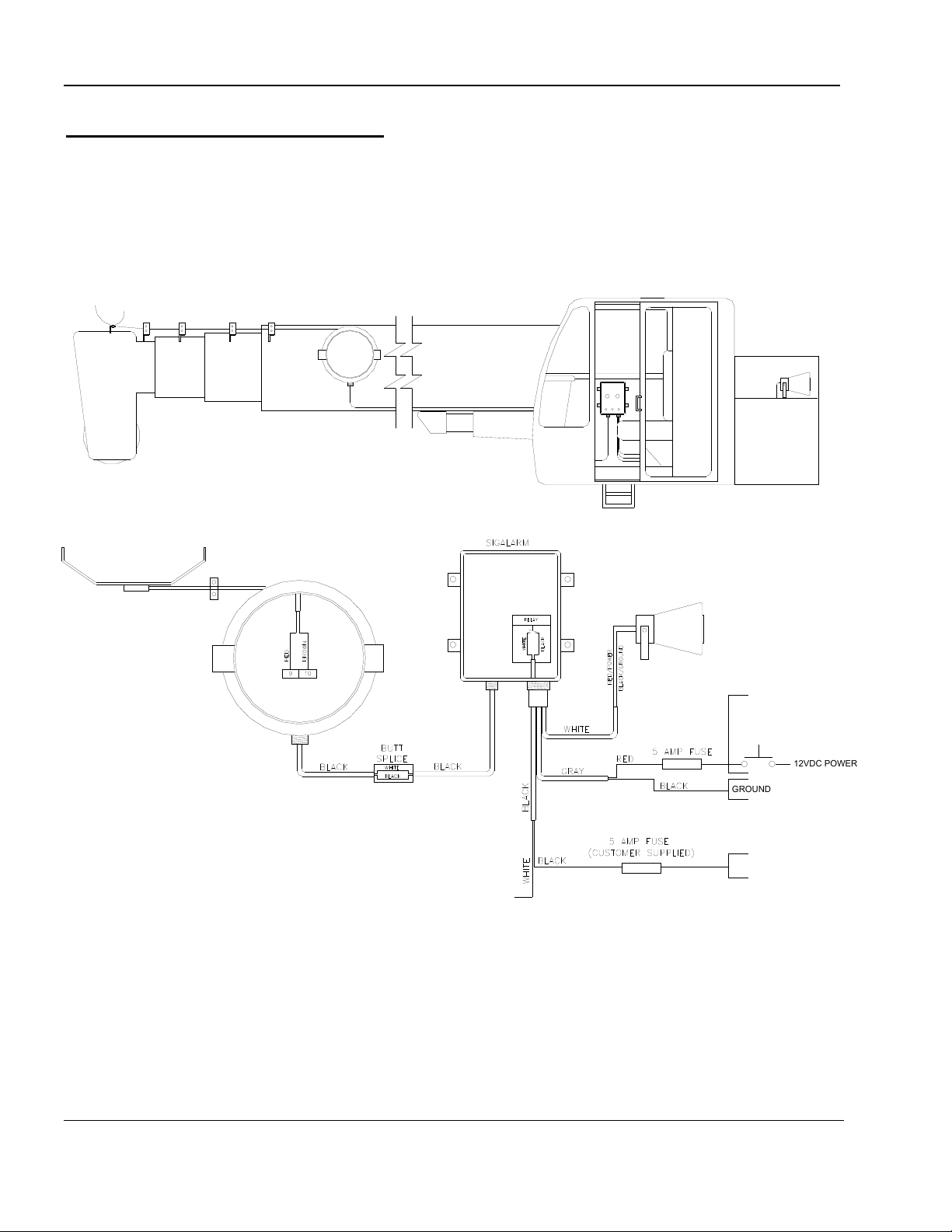
1 INSTALLATION DIAGRAM
+24V
GROUND
GROUND
RECOMMENDED TO WIRE 12V
SUPPLY POWER THROUGH A
BOOM PROXIMITY SWITCH THAT
PROVIDES POWER ONLY WHEN
THE BOOM IS INITIALLY RAISED
12VDC POWER
RELAY
OUTPUT
Relay Input

3
SkyAzúl, Equipment Solutions www.skyazul.com 301-371-6126
2 PIGTAIL DIAGRAM

4
SkyAzúl, Equipment Solutions www.skyazul.com 301-371-6126
3 INTERNAL CABLE REEL DIAGRAM

5
SkyAzúl, Equipment Solutions www.skyazul.com 301-371-6126
4 MOUNTING OF THE REEL, CABLE GUIDES, AND BRACKETS
After you have determined
the best location for
mounting the reel, check
that the antenna sensor will
have a unobstructed
straight line between the
reel and guides. (it is
recommended that the first
cable guide be 4-5 feet in
front of reel and 4-5 inches
below where antenna
releases off reel in order to
supply proper tension).
The extra antenna sensor NOT wound on the reel provides for the distance between reel
location and tip when retracted. This can be left loosely wound around reel so that it is out of
the way during reel installation.
If needed install additional antenna sensor between fixed section of the reel and the
ANTENNA LEAD-IN Cable coming out from control box. Be sure there is enough slack for any
possible movement in this area and that the cables are routed out of the way from wear or
possible abuse.
Reel and cable guides should be mounted without violating the structural integrity of the
equipment. The brackets and hardware furnished with your SIGALARM should be adequate
for most installations.
The main considerations are:
1. The antenna sensor is kept 2-7
inches off the solid metal boom.
(Keep in mind that some boom
shielding might occur and
sensitivity adjustments may
need to be made)
2. The reel, cable guides, and
brackets are securely mounted
to boom.
3. You have crimped the (2) female
pins provided on the end of the
sensor cable at tip (slide heat
shrink connector over antenna
prior to inserting these female
pins into jumper connector).

6
SkyAzúl, Equipment Solutions www.skyazul.com 301-371-6126
4. The antenna sensor end from reel is firmly clamped at
the boom tip to the deadman with a V clamp provided
prior to the jumper connector.
5. The antenna sensor can freely slide through the guides
6. Pigtail Assembly (provided) is installed correctly:
Attach angle brackets (supplied) to each side of the tip
on the last extension section, use the remaining (2) V
clamps, clear hose, and hardware provided to attach
antenna pigtail. Run this cable back to the (quick
disconnect) jumper connector and attach.
7. You have extended the boom to check mechanical
operation.
8. Prior to operation - Use the hold to test button on the control panel to verify that the entire
antenna system is working correctly.
TEST BUTTON

7
SkyAzúl, Equipment Solutions www.skyazul.com 301-371-6126
4.1 CABLE REEL DIMENSIONS – LG154
8
SkyAzúl, Equipment Solutions www.skyazul.com 301-371-6126
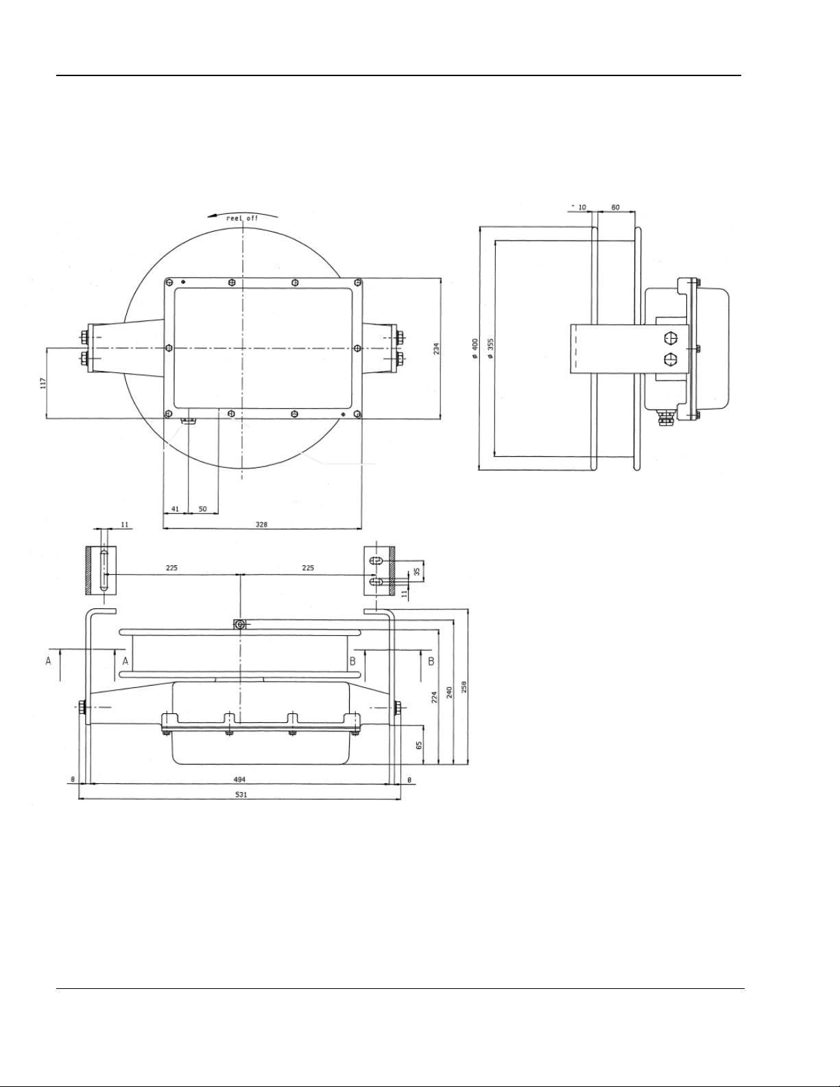
4.2 CABLE REEL DIMENSIONS – KT200
A - A B - B

9
SkyAzúl, Equipment Solutions www.skyazul.com 301-371-6126
CABLE REEL MOUNTING PLATE DIMENSIONS – KT200

10
SkyAzúl, Equipment Solutions www.skyazul.com 301-371-6126
4.3 BOOM INSTALLATION LOCATIONS

11
SkyAzúl, Equipment Solutions www.skyazul.com 301-371-6126
4.4 6-PIN SCHEMATIC

12
SkyAzúl, Equipment Solutions www.skyazul.com 301-371-6126
5 ANTENNA INSTALLATION
Antenna leads use a minimum of 22 gauge wire. These 2 wires can be run
internal or external of the Nycoil. These wires are to be connected to the
Multipin Connector at the end of the pigtail. Female pins are included and are
to be inserted in holes 1 and 3.Pins 2 and 4 will have a jumper pre inserted.
Power for the SIGALARM should come from a 12V DC supply circuit that
powers other 12 volt accessories.
Note: A ground wire should be mounted to a good vehicle ground at the point of
picking up power. The negative terminal of battery used to supply Sigalarm
should be grounded to chassis (this measurement should be less than two
ohms)
SIGALARM control box needs to be grounded by sanding off the exposed
mounting hole and connect to a good vehicle ground. Battery and Horn
and External Strobe-Three cables with six pin male connector.
White cable is for the external horn
Gray cable is for 12VDC power source. RED +, BLACK -
Black Cable is for the External Strobe.
White is connected to 24V
Black is connected to the red positive supply wire of strobe
Connect the black wire of the strobe directly to ground
Note: Reset button must be pushed when the external strobe is used whether
power lines are detected or not in order to return internal relay to its normal
closed position.
Antenna Lead-In -Single black shielded cable with 2 pin male connector, to be
ran to antenna port where the wires tie into the Nycoil. These wires should be
soldered and covered with shrink tube. “Note” when cutting to fit insure that the
ground wire is long enough to be able to ground to the vehicle

13
SkyAzúl, Equipment Solutions www.skyazul.com 301-371-6126
6 TESTING
CIRCUIT AND ANTENNA SENSOR TEST
Push the TEST BUTTON and hold it there: the green light should remain on, the
red light will flash, the interior buzzer sound, and the exterior horn(s) sound. This
should occur within the first 3 seconds after pushing and holding the test button. If
the green light goes off during this time, there is a cut in the antenna, a jumper pin
problem, or an internal failure.
7 TROUBLESHOOTING TIPS
APPLY POWER TO SYSTEM
If power LED (green) does not illuminate, check to make sure the battery cable
was connected to the battery with the correct polarity.
If green power LED still doesn't illuminate, clean and tighten battery connections
and affirm that power is getting to unit. Check that the black wire is connected to
negative, and the red wire is connected to positive.
NOTE: Verify that the equipment to which the SIGALARM PWS is mounted is
negatively grounded.
GREEN POWER LED
With power available to the system, push and hold reset button. If power LED
does not illuminate, but horns alarm, and the red alarm LED is flashing the power
LED may be defective or antenna is bad.
(Call Factory 1-800-589-3769)
INTERNAL HORN
Repeat same steps as above. Check connectors and cable. If still inoperable,
check wires to EXT horn for pinching (shorts). If problem remains, call the factory.
BATTERY CABLES
Check battery posts and the battery cable for damaged and verify that 12VDC is being applied to
the control module.

14
SkyAzúl, Equipment Solutions www.skyazul.com 301-371-6126
8 SPECIAL NOTES
Adjust controls to safe working conditions at each location. It is recommended
that you be assisted by a person on the ground to further insure that you do not
contact the power line during set-up of SIGALARM.
If the equipment is wired for 110/220VAC night lights which are not completely
shielded or grounded, the SIGALARM may be activated in its most sensitive
position by the electric field that exists when lights are in operation.
Since atmospheric electrical storms generate a similar field to voltage
transmission lines, the SIGALARM may be activated during such storms,
depending upon distance and intensity.
When operating in close proximity to high voltage power lines, vehicles should
be prohibited from traveling between the crane/boom and power line.
SPECIAL NOTES:
It is DANGEROUS to operate any "high lift" vehicle beneath high voltage
lines that are energized. Confirm their condition with SIGALARM.
It is DANGEROUS to operate any equipment directly over high voltage
lines. It will be necessary to re-calibrate the unit if you must work above
power lines. This is highly recommended against.
It is DANGEROUS to operate large equipment in an electrical storm.
IT IS RECOMMENDED THAT WHEN MULTIPLE VOLTAGE LINES ARE
PRESENT, THAT THE UNIT BE SET TO THE LOWEST VOLTAGE LINES
Table of contents


