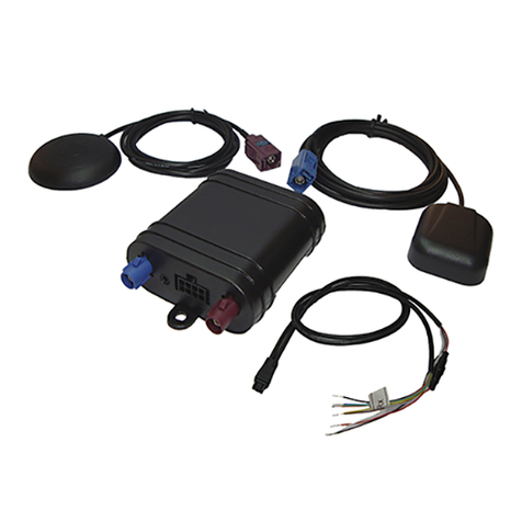
Skypatrol ST7200 User manual

Troubleshooting Guide
ST7200
Skypatrol
ST7200 Troubleshooting Guide
Revision 0.0

ST7200 Troubleshooting Guide
Ver. 0.0
Revision History
Revision Date Author Notes
0.0 06/09/2014 Renato Motta Initial draft version

ST7200 Troubleshooting Guide
Ver. 0.0
Table of Contents
REQUIREMENTS .................................................................................................................... 1
DIAGNOSTICS PROCEDURES ............................................................................................ 1
POWER UP TEST .................................................................................................................... 2
SERIAL COMMUNICATION TEST .................................................................................... 2
NETWORK TEST .................................................................................................................... 3
OUTPUT TEST ......................................................................................................................... 3
COMMUNICATION MODULE TEST ................................................................................. 4
INPUT TEST ............................................................................................................................. 5
GPS TEST.................................................................................................................................. 6
MEMORY TEST ...................................................................................................................... 7

ST7200 Troubleshooting Guide
Ver. 0.0
Page 1
Requirements
For these tests the requirements are:
An Skypatrol ST7200 series modem
A computer with any terminal application that is capable of sending data to
the serial port.
Active SIM card with GPRS capability
Application to manage GPRS/UDP communications
A relay and multimeter.
Diagnostics Procedures
YES NO
1 – Are the LEDs on? Next Step Run “Power up test”
2 – Do you see serial activity from the unit? Next Step Run “Serial communications test”
3 – Is the unit attaching to the network? Next Step
Run “Network test”
4 – Is the output fully functional? Next Step Run “Output test”
5 – Is the unit connecting correctly to the network?
Can it send reports?
Next Step Run “Communication Module Test”
6 – Is the inputs fully functional? Next Step Run “Input test”
6 – Is the unit reporting accurate positions? Next Step Run “GPS test”
7 – Is the unit keeping its programming through the
reset process?
Next Step Run “Memory test”

ST7200 Troubleshooting Guide
Ver. 0.0
Page 2
Power up Test
This is a visual test.
When the customer powers on the device he/she will see the LEDs turn on. If the
LEDs don’t turn on, connect the ignition sense cable (white cable) to the main power
source (12 V), the LEDs should turn on. If the device is connected correctly to the
serial port, it should show a message similar to “Main Version: S4x1-1119B3” when
the device powers on.
Should the LEDs remain off and no message is shown on the serial port, verify the
power supply if it is at least 12V, if everythin is OK with the power supply, it’s
possible that the unit cannot power up.
Serial Communication Test
This test verifies whether the device can send and receive commands via the serial
port.
Connect the device to the serial port with the configurations below:
Bits per second: 115200
Data bits: 8
Parity: None
Stop bits: 1
Flow control: None
Then power up the device, it will show on the serial port a message similar to “Main
Version: S4x1-1119B3” depending on your firmware version.
Send any command or character string to the device it will reply with “*”, so if you
see a “*” symbol for every character you send the device can receive and send data
though the serial port.
When you send the password of the device, it will reply with:
************
Accepted
After sending the password, all commands and characters will be shown normally.

ST7200 Troubleshooting Guide
Ver. 0.0
Page 3
Network Test
The network test can be verified by the LED behavior. The GSM/cellular LED (Blue)
reflects the state of the GSM registration.
o Blinking once a second means: Searching for GSM network
o Blinking every 3 seconds means: GSM lock
You can send the command below to check the GSM registration.
+XT:7050,1
The response is a message string in the format:
$$<UID>,7050,<GSM>,<GPR>,<PDP>,<HD>,<HO>,<PU>,<R>,<%GPS>,<%GPSQ>,
<%GSM>,<%GPR>,<%PDP>,<LV>,<HV>,<CX>,<DBO>,<ABI>,<DBI>,<SO>,<SI>,<
SS>##
<GSM> is GSM registration state: 0=Not Reg, 1=Home, 2=Search, 3=Denied, 4=Unknown,
5=Roaming
<GPR> is GPRS registration state: 0=Not Reg, 1=Home, 2=Search, 3=Denied, 4=Unknown,
5=Roaming
<PDP> is GPRS PDP state, 0=Deactivated, 1=Activated
<%GSM> is Percent lost GSM
<%GPR> is Percent lost GPRS
<%PDP> is Percent lost PDP context activation
If the device cannot register to the network, verify the SIM card and the location to
check for coverage issues. The device will always try to register automatically to the
network.
Output Test
For this test we will need a relay and a multimeter.
Connect PIN 86 and 30 of the relay to a 12V power source and connect PIN 85 to the
ST7200 output (Green wire).
Send the command to set the output to a short circuit
+XT:7005,2,2
You should hear the relay click. With a multimeter check the voltage at pin 87a of the
relay, there should be no current.
Send the command to set the output to an open circuit
+XT:7005,1,2
You should hear the relay click. With a multimeter check the voltage at pin 87a of the
relay, there should be a 12V current.

ST7200 Troubleshooting Guide
Ver. 0.0
Page 4
Communication Module Test
This test verifies the communication module’s functionality.
For this test you will need a computer connected to the internet, an application able to
receive and send data over UDP and a public SIM card with GPRS/data plans.
Setup the ST7200 device to the correct IP and port of your server and correct APN of
your SIM card and choose UDP (w/ commands) protocol, with the command
+XT:1010, then after the device has registered to the network send the command
+XT:7001,1 via the terminal and you should receive on your UDP application a
message from the device in the format:
$$<UID>,7001,<D>,<T>,<LT>,<LN>,<AL>,<SP>,<HD>,<SV>,<HP>,<BV>,<GS>,<OT
>,<CQ>,<MI>,<IG>,<BB>,<PM>##
Ex:
$$354660046703651,7001,2014/06/09,19:28:32,25.80207,-80.33222,3.0,0,0.0,12,0.8,12.5,1,2,16,0,0,4.0,1##
After you have received this message send via UDP the command +XT:7050,1 in the format:
+XT:<UID>,7050,1##
Ex:
+XT:354660046703651,7050,1##
You will receive on your UDP application the response of the +XT:7050 command.
If you don’t receive any messages via UDP from the device, verify the SIM card APN
and the location to check for coverage issues. Send the command +XT:7050,1
The response is a message string in the format:
$$<UID>,7050,<GSM>,<GPR>,<PDP>,<HD>,<HO>,<PU>,<R>,<%GPS>,<%GPSQ>,
<%GSM>,<%GPR>,<%PDP>,<LV>,<HV>,<CX>,<DBO>,<ABI>,<DBI>,<SO>,<SI>,<
SS>##
<DBO> is Data Bytes Out, 10000000 max
Check the <DBO> parameter to see how many bytes of data the device has sent since
the last clear.
If you don’t see any data going out, run the “Network Test” to check for GPRS
registration.

ST7200 Troubleshooting Guide
Ver. 0.0
Page 5
Input Test
For this test you will need a computer connected to the internet, an application able to
receive and send data over UDP and a public SIM card with GPRS/data plans.
Setup the ST7200 device to the correct IP and port of your server and correct APN of
your SIM card and choose UDP (w/ commands) protocol, with the command
+XT:1010, wait for the device to register to the network.
Send to the device the command
+XT:3001,0,1
+XT:3002,0,1
+XT:3015,3
After sending the commands connect the ignition wire (white) to a 12V source and
verify that the device sends a message when the wire is connected and disconnected to
the power source.
Alert message for Ignition ON are EV# 6011and EV# 6013 respectively.
Ex:
Ignition on report:
$$354660046703651,6011,2014/06/09,19:58:53,25.80236,-80.33195,-81.5,0,0.0,12,0.8,12.5,17,0,1,4.1,1##
Ignition off report:
$$354660046703651,6012,2014/06/09,19:58:58,25.80234,-80.33198,-76.3,0,0.0,12,0.8,12.4,16,0,1,4.2,1##
Now connect the input2 wire (yellow) to a ground source and wait for the unit to reply,
then remove the input2 wire to the ground source and wait for the unit to reply.
Alert message for auxiliary input going high is EV# 6019and going low is EV# 6020
respectively.
Ex:
Input2 high:
$$354660046703651,6019,2014/06/09,20:04:43,25.80208,-80.33198,-49.7,0,0.0,10,1.1,12.5,17,0,1,4.1,1##
Input2 low:
$$354660046703651,6020,2014/06/09,20:04:21,25.80206,-80.33198,-54.7,0,0.0,10,1.0,12.5,16,0,1,4.1,1##
If you don’t receive any messages via UDP from the device, verify the SIM card APN
and the location to check for coverage issues. The device will always try to register
automatically to the network. Run the “Network Test” and “Communication Module
Test” to check for GPRS registration.

ST7200 Troubleshooting Guide
Ver. 0.0
Page 6
GPS Test
This test verifies the communication between the device with it internal GPS and if the
GPS it is working correctly.
The GPS test can be verified by the LED behavior, the GPS LED (Green) reflects the state
of the GPS fix
o Solid mean: Searching for satellite
o Blinking every second means: GPS lock
Send the command +XT:7001,2, the response of the command is a string in the format:
$$<UID>,7001,<D>,<T>,<LT>,<LN>,<AL>,<SP>,<HD>,<SV>,<HP>,<BV>,<GS>,<OT
>,<CQ>,<MI>,<IG>,<BB>,<PM>##
Ex:
$$354660046703651,7001,2014/06/09,20:21:36,25.80226,-80.33211,-31.8,0,0.0,10,0.9,12.5,1,2,15,0,0,4.1,1##
If you don’t see a valid date, time, latitude and longitude from the device, send the
command below to check the GPS fix quality.
+XT:7050,1
The response is a message string in the format:
$$<UID>,7050,<GSM>,<GPR>,<PDP>,<HD>,<HO>,<PU>,<R>,<%GPS>,<%GPSQ>,
<%GSM>,<%GPR>,<%PDP>,<LV>,<HV>,<CX>,<DBO>,<ABI>,<DBI>,<SO>,<SI>,<
SS>##
<%GPS> is Percent lost GPS
<%GPSQ> is Percent lost GPS based on 5 Sat Quality Factor
If the device fails to get a valid GPS fix, then move the device to a location with a
better view of the sky and wait up to 15 minutes. If the device doesn’t report a valid position
then it’s possible that there is a inconvenience with the GPS module.

ST7200 Troubleshooting Guide
Ver. 0.0
Page 7
Memory Test
This tests checks to see if the device keeps it’s configuration after a power up cycle.
For this test send the command below and reset the unit.
+XT:3040,5,1,0,1,0,0,0,11.7,1,0,1,0,0,0,1,0,1,0,5,240,3,0,0,00001
Response:
$$<UID>,3040,5,1,0,1,0,0,0,11.7,1,0,1,0,0,0,1,0,1,0,5,240,3,0,0,00001##
Reset the unit: +XT:7003
Response:
$$<UID>,7003##
Resetting in 5 seconds
Main Version: S4x1-1119B3
Check if the device kept the configuration, send the command: +XT:3050
Response:
$$<UID>,3050,5,1,0,1,0,0,0,11.7,1,0,1,0,0,0,1,0,1,0,5,240,3,0,0,00001##
If the unit showed a configuration different form the one sent, try saving the configuration to a
profile (this is the recommended procedure) and reset the unit.
Send:
+XT:3040,5,1,0,1,0,0,0,11.7,1,0,1,0,0,0,1,0,1,0,5,240,3,0,0,00001
Response:
$$<UID>,3040,5,1,0,1,0,0,0,11.7,1,0,1,0,0,0,1,0,1,0,5,240,3,0,0,00001##
Send:
+XT:7008
Response:
$$<UID>,7008,00001##
Reset the device it should now always revert to the saved profile even if it loses the current
configuration.
Note: It’s not ok that the device lost configuration even without the +XT:7008 command,
losing the configuration when not using the +XT:7008 command could indicate a problem
with the power source.
Other manuals for ST7200
1
Table of contents
Other Skypatrol GPS manuals

Skypatrol
Skypatrol TT8540 User manual

Skypatrol
Skypatrol SP8600 User manual

Skypatrol
Skypatrol ST7200 User manual

Skypatrol
Skypatrol SP4700 User manual

Skypatrol
Skypatrol SP9700 User manual

Skypatrol
Skypatrol Evolution User manual

Skypatrol
Skypatrol TT8950 User manual

Skypatrol
Skypatrol SP4600 User manual
Skypatrol
Skypatrol SP9600 User manual

Skypatrol
Skypatrol SP1824 User manual