Skypatrol SP2600 User manual

SP2600

Document Title SP2602 User Manual
Version 1.0
Date 2015-11-13
Status Release
Copyright and Disclaimer
The user manual may be changed without notice.
Without prior written consent of Skypatrol Company Ltd., this user manual, or any
part thereof, may not be reproduced for any purpose whatsoever, or transmitted in
any form, either electronically or mechanically, including photocopying and
recording.
Skypatrol Company Ltd. shall not be liable for direct, indirect, special, incidental,
or consequential damages (including but not limited to economic losses, personal
injuries, and loss of assets and property) caused by the use, inability, or illegality to
use the product or documentation.
SP2602 User Manual

INSTRUCTIONS OF SAFETY
This chapter contains information on how to operate “SP2602” safely.
By following these requirements and recommendations you will avoid
dangerous situations. You must read these instructions carefully and follow the
strictly before operating the device!
Device with internal battery in long-time storage need regular charged to
avoid over-discharge and need store in the dry and cool place if the storage
time is longer than three months.
The device uses a 8V-32V DC power supply. The nominal voltage is 12V
DC. It is advised to transport the device in an impact-proof package.
Before usage, the device should be placed so that its LED indicators are
visible, which show what status of operation the device is in.
Before dismountle the device from the vehicle, disconnect all the
connection.
SP2602 User Manual

Contents
SP2602 Introduction.....................................................................................6
SP2602 Specifications..................................................................................7
Product overview..........................................................................................8
Check Part List.............................................................................................8
Standard Part List.........................................................................................8
Optional Part List.........................................................................................9
Getting Started............................................................................................11
The Backup Battery Switch........................................................................11
Open The Case...........................................................................................12
Insert SIM Card..........................................................................................13
Lock SIM Card Slot...................................................................................14
Close The Case...........................................................................................15
Install Direction .........................................................................................16
Installing the External GPS Antenna(Optional)..........................................17
Interface Denition & Cable Color.............................................................18
PIN Denition............................................................................................19
Power Connection......................................................................................20
Ignition Detection ......................................................................................21
Digital Inputs..............................................................................................22
SOS Button.................................................................................................23
SP2602 User Manual

Digital/Analog Multiplex Inputs....................................................................24
Digital Outputs...............................................................................................25
Serial Port / UART Interface..........................................................................27
Picture Upload to Remote Server...................................................................28
MDT..............................................................................................................29
Fuel Level Detection......................................................................................30
Remoter Control Idatalink Device.................................................................31
Voice Interface...............................................................................................32
1-Wire Bus.....................................................................................................33
User Combine Command...............................................................................34
SMS Report Explanation...............................................................................35
Common commands......................................................................................38
Set User Phone Number................................................................................38
Set User Password.........................................................................................39
Set Report Interval Mode Switching Condition............................................40
Set Position Report Interval To User.............................................................41
Set SIM Card APN........................................................................................43
Set GPRS Main Server ..................................................................................44
Set GPRS Backup Server ..............................................................................46
Set Position Report Interval To GRPS Server................................................48
LED Indicator Behavior ................................................................................50
SP2602 User Manual

6
SP2602 User Manual
SP2602 Introduction
The SP2602 is a new generation vehicle or asset tracking and telemetry
device designed for maximum autonomy and ease of use. It is intended for use
to protect and trace items such as containers-caravans-fixed plant-construction
equipment-in shore boats and truck trailers. It can also be used for temporary
tracking of vehicles for consignment purposes as well as covert “slap and track”
operations. It has the features as follows:
»Double GPRS servers
»Flexible packet
»Dynamic report
»Profile configuration
»Private hour mode
»Driving behavior
»Accident detection
»Single event
»Combination event
»Event flow
»Output wave shape
»Geo-fence
»Firmware OTA

7
SP2602 User Manual
SP2602 Speci ications
Physical Dimension 90(L)x46(W)x20(H)mm
Weight ~83g (With battery)
Environment Operating
temperature
-40°C ~+80°C (without backup battery)
-10°C ~+50°C (with backup battery)
I/O connector ACC input 1 channel
Digital output 1 channel
USB Mini USB 2.0
CPU ARM STM32F103 UcOS
LED indicator 3 LED indicators GSM & GPS & POWER
Power supply External DC 8 to 32V
Backup battery Type Rechargeable, Li-Po 3.7V, 750mAh
Power
consumption
≥230mA (Active Tracking)
≥25mA (Power Saving Mode)
≥10mA (Deep Sleeping Mode)
GSM/GPRS Model
Built-In
Air Prime HL6528
Quad band: GSM 850/900/1800/1900MHz
Multiple-slot Class 8 (dual band)/10 (quad band)
GPRS class 10/Station class B
TCP/IP over PPP
SIM card 1.8V & 3.3V
GPS
Internal antenna 25*25 with amplifier
External antenna N/A
Model uBlox NEO 6M
Channel 50 Parallel Channels
Accuracy Autonomous<2.5M
Sensitivity -162dBm
Sensor Accelerate sensor Built-In, 3-axis
Flash storage 16Mbits Built-In

8
SP2602 User Manual
Product overview
Check Part List
Before starting, check all the following items have been included with your device. If
anything is missing, please contact your supplier.
Standard Part List

USB Cable
Relay
Fastening Tape
Fuse
9
SP2602 User Manual
Optional Part List
10
SP2602 User Manual
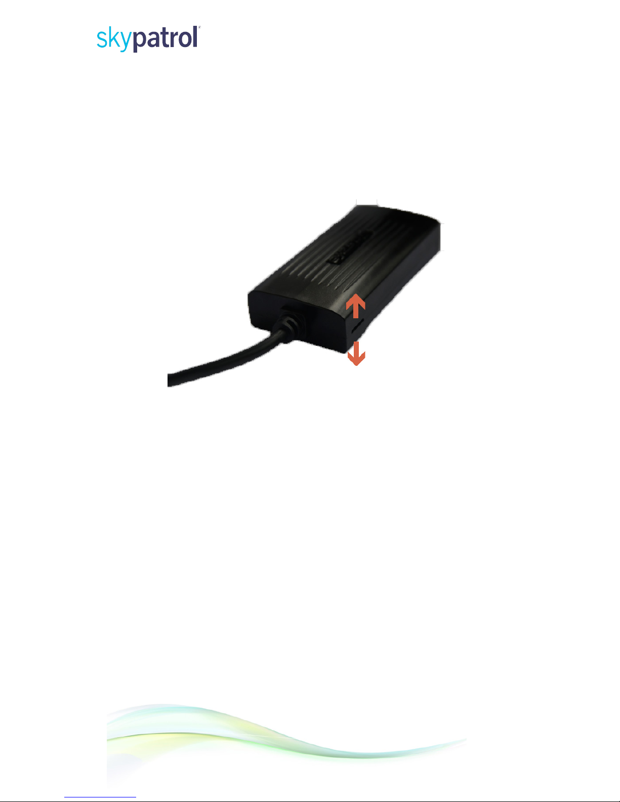
Getting Started
Open The Case
Forced open up via the gap.
11
SP2602 User Manual
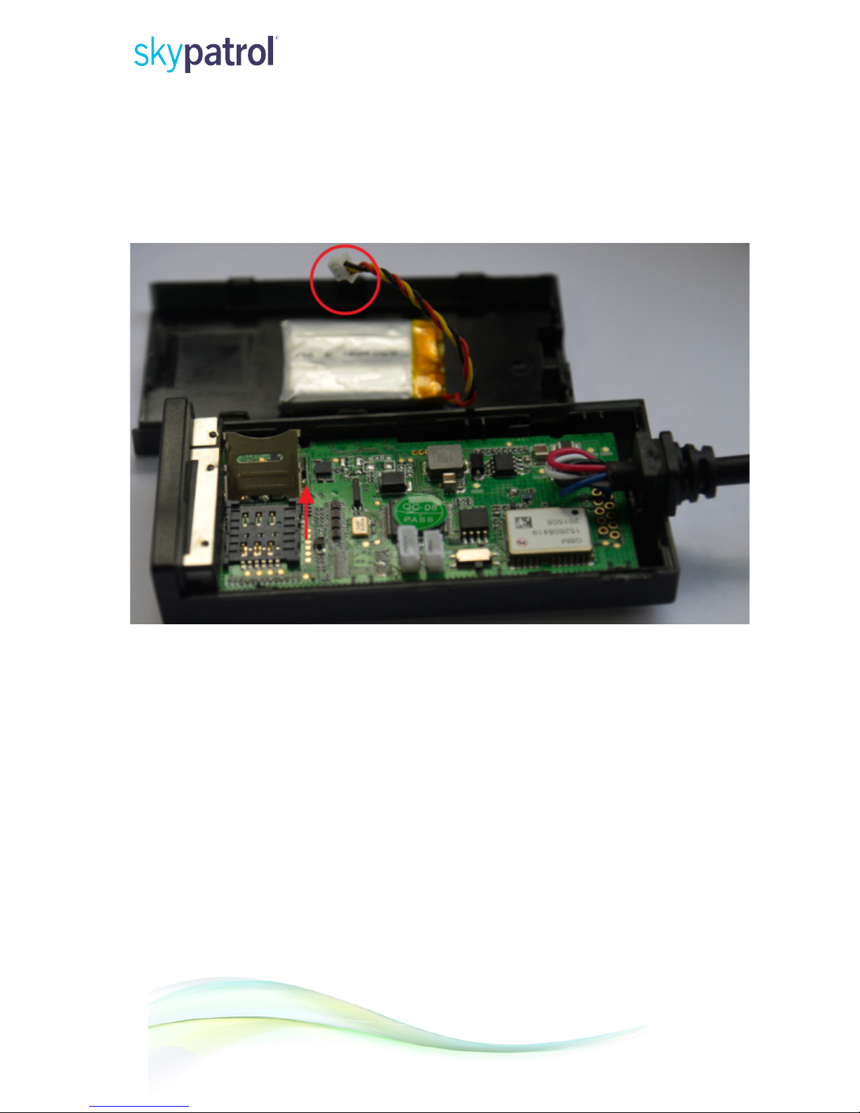
Open The Sim Card Cover
Disconnect the battery and device first, and then open the cover.

12
SP2602 User Manual
Insert SIM Card
Insert the SIM card into the holder and please notice the cut mark position.
Device use 1.8V or 3.3V Micro-SIM card, SIM card size 12*15mm.

13
SP2602 User Manual
Lock SIM Card Slot
Close the SIM card slot and lock it. Connect the battery connection.

14
SP2602 User Manual
Close The Case
Place the cover on the bottom in the position as shown in the photo and close until it
snapped.

15
SP2602 User Manual
Installation Direction
Device have built-in GSM and GPS antenna, the signal of GSM and GPS will
be affected by installation direction of device. The recommended installation
direction is as follows:
Face Up

17
SP2602 User Manual
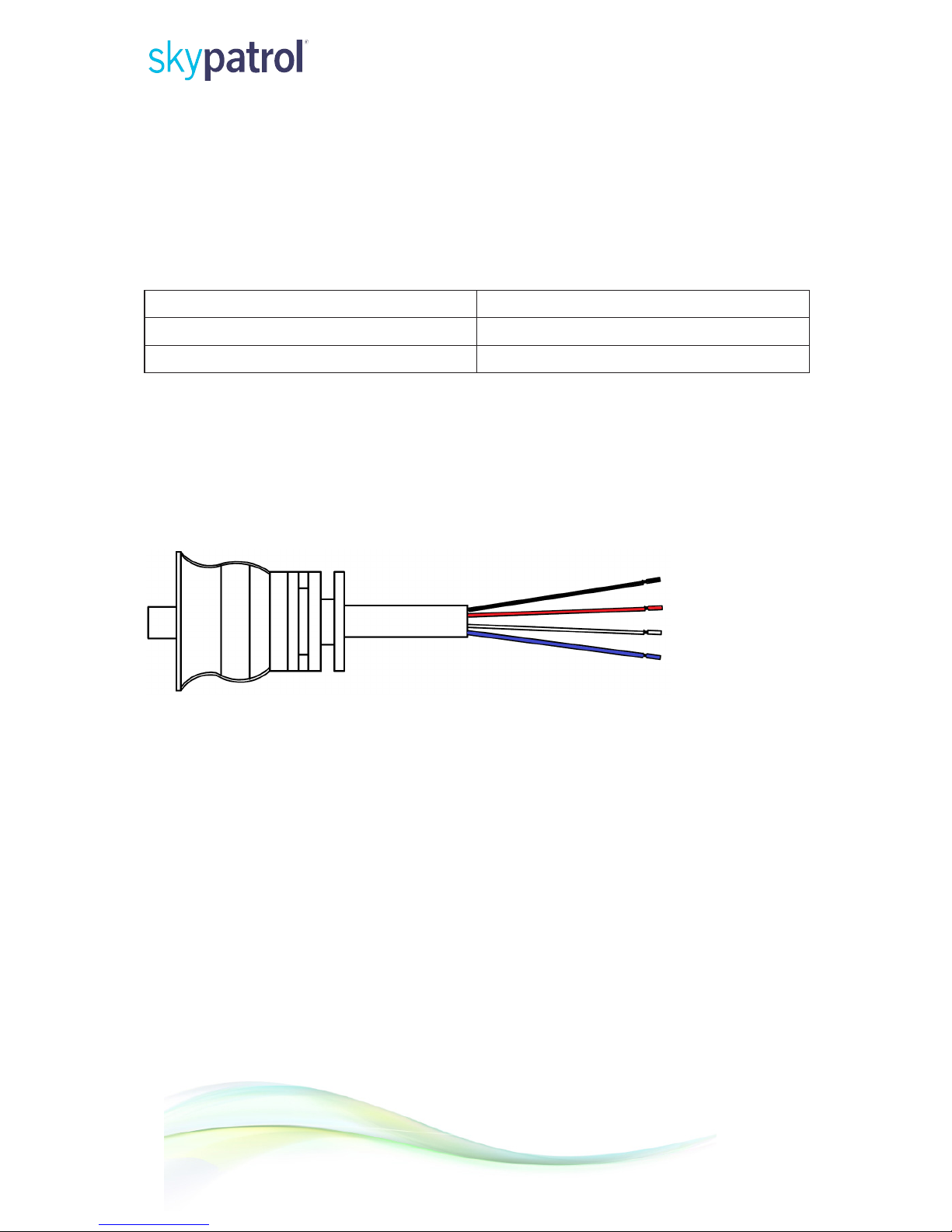
The number of I/O connectors can be customized by the customer, the following is
the definition of the 4 I/O connectors device.
Colour Name Definition Remark/Default
Black GND Negative (-)
Red VCC Positive (+) 8V-32V DC
White ACC ACC/Ignition signal input High level active
Blue OUT1 Digital output channel 1

18
SP2602 User Manual
Power Connection
VCC and GND are the power input pins. The input voltage range for this device is
from 8V to 32V. The device is designed to be installed in vehicles that operate on
12V or 24V systems without the need for external transformers.
GND
VCC 8V-32V
50 CM
Fuse
19
SP2602 User Manual
Digital Outputs
There are three digital outputs on device. All are of open drain type and the maximum
drain current is 200 mA. Each output has the built-in over current and recovery PTC fuse.
Logical State Electrical Characteristics
Enable 1.5~20V@Ids<200mA
Disable Open drain
Device can be configured as digital output according default mode, trigger any event will
generate digital output action.
Note:
OUT1 will latch the output state during reset
OUT1
50 CM

20
SP2602 User Manual
Out1 connect to relay.
50 CM
85(-)
87
30
87a
86(+)

21
SP2602 User Manual
User Combine Command
Device support to combine multiple commands through a SMS message sent to the
device. The commands are separated by a comma, the maximum length of the combined
command is 256 bytes. Formats as below:
User
name
Separated
Comma
Command
1
Separated
Comma
Command
2
Separated
Comma
... Command
n
1234 , UNO;139
12345678
, UPW;
4567
, ... USP0;
1;24
H;0;W
Command Reply Explanation:
After device received the user's command will immediately to process and use SMS
reply to the user, reply SMS has two kinds: command error, command success.
Command Error SMS
Content of message Explanation
G3C V1.00
ERR
Device name, Firmware version
Command Error
Command Success SMS
Content of message Explanation
G3C V1.00
UPW:1234
Ext_Pwr=11.94V
BAT=3.90V
#3
Device name, Firmware version
Command Setting
External power voltage
Built-in battery voltage
Consumed messages
This manual suits for next models
1
Table of contents
Other Skypatrol GPS manuals

Skypatrol
Skypatrol SP9700 User manual

Skypatrol
Skypatrol TT8750 Assembly instructions

Skypatrol
Skypatrol SP1824 User manual

Skypatrol
Skypatrol ST7200 User manual

Skypatrol
Skypatrol TT8540 User manual

Skypatrol
Skypatrol ST7200 User manual

Skypatrol
Skypatrol SP4700 User manual

Skypatrol
Skypatrol TT8950 User manual

Skypatrol
Skypatrol SP9600 User manual

Skypatrol
Skypatrol SP4600 User manual


