Skypatrol SP4700 User manual

SP4700s
erie
s products
user manua
1
SP4700 User manual

SP4700s
erie
s products
user manua
2
Copyright and Disclaimer
The user manual may be changed without notice.
Without prior written consent of Skypatrol LLC Company Ltd., this user manual, or any
part thereof, may not be reproduced for any purpose whatsoever, or transmitted in
any form, either electronically or mechanically, including photocopying and recording.
Skypatrol LLC Company Ltd. shall not be liable for direct, indirect, special, incidental, or
consequential damages (including but not limited to economic losses, personal
injuries, and loss of assets and property) caused by the u e, inability, or illegality to
use the product or documentation.
FCC Radiation Exposure Statement:
This equipment complies with FCC radiation exposur limits set forth for an
uncontrolled environment. This equipment should be installed and
minimum distance 20cm between the radiator & your body.
operated with
FCC Warning
This device complies with Part 15
following two conditions:
of the FCC Rules. Operation is subject to the
(1) This device may not cause harmful interference, and (2) this device must accept
any interference received, including interference that may cause undesired operation.
NOTE: Any changes or modifications to this unit not expressly approved by the arty
responsible for compliance could void the user's authority to operate the equipment.

SP4700s
erie
s products
user manua
3
INSTRUCTIONS OF SAFETY
This chapter contains information on how to operate “SP4700 series product” safely.
By following these requirements and recommendations you will avoid dangerous
situations. You must read these instructions carefully and
operating the device!
ollow them strictly before
The built‐in battery of device need to be charged regularly every two months to
avoid over‐discharge and need to be stored in the dry and cool place.
The device uses 8V‐32V DC power supply. The nominal voltage is 12V DC.
It is advised to transport the device in an impact‐proof package.
Before usage, the device should be placed properly to ensure LED indicators (device
operation status) are visible.
Before demounting the device from the vehic e, it should be disconnecting all the
connection first.

SP4700s
erie
s products
user manua
4
CONTENTS
1.
SP4700 Series Introduction.....................................................................................5
2.
SP4700 series products specifications .......................................................................6
3.
Product overview.......................................................................................................7
3.1
Check Part List.................................................................................................7
3.2
Open the device cap.........................................................................................9
3.3
Install SIM card..............................................................................................10
3.4
Connect USB data line...................................................................................10
3.5
Close the case.................................................................................................11
3.6
Installation Direction .....................................................................................12
4.
Interface Definition & Cable Color.........................................................................13
5.
User Combine Command.........................................................................................13
5.1
Command Error SMS ....................................................................................14
5.2
Command Success SMS................................................................................14
6.
SMS Report Explanation .........................................................................................15
6.1
“W” Mode Report..........................................................................................15
6.2
“T” Mode GPS Report...................................................................................16
6.3
“T” Mode LBS Report...................................................................................17
7.
Common commands ................................................................................................18
7.1
Set User Cell Phone Number.........................................................................18
7.2
Set User Password..........................................................................................19
7.3
Set Report Interval Mode Switching Condition.............................................20
7.4
Set timing Report Interval to User.................................................................21
7.5
Set SIM Card APN.........................................................................................22
7.6
Set GPRS Main erver...................................................................................23
7.7
Set GPRS Backup Server...............................................................................24
7.8
Set Timing Report Interval to GRPS Server..................................................26
8.
LED Indicator Behavior...........................................................................................27

SP4700s
erie
s products
user manua
5
1. SP4700 Series Introduction
The SP4700 series products are new generation vehicle or asset trackers and
telemetry device designed for maximum autonomy and ease for use. It is intended
for use to
protect and trace items such as containers‐caravan ‐fixed plant‐construction
equipment‐in
shore boats and truck trailers. It can also be used for temporary
tracking of vehicles for onsignment purposes as well as covert “slap and track”
operations. The features as follows:
Double GPRS servers
Flexible packet
Dynamic report
Profile
Private hour mode
Driving behavior
Accident detection
Single event
Combination event
Event flow
Output wave shape
Geo‐fence
Firmware OTA

SP4700s
erie
s products
user manua
6
2. SP4700 series products specifications
Specification
Dimension
94(L)X47(W)X20.5(H)mm
Weight
~83g (With battery)
Environment
Operating
temperature
‐40°C ~+80°C (without backup battery)
‐10°C ~+50°C (with backup battery)
USB
Mini USB
2.0
CPU
ARM
STM32F103
LED indicator
3 LED indicators
GSM & GPS & POWER
Power supply
External
DC 8 to 32V
Backup battery
Type :
Rechargeable, Li‐Po .7V, 750mAh
Power
consumption
≥230mA (Active Tracking)
≥25mA (Power Saving Mode)
≥10mA (Deep Sleeping Mode)
GSM/GPRS
Model (3G)
Built‐In
Air Prime HL8548
Band: GSM 850/900/1800/1900MHz
UMTS 850/900/1800/1900/2100MHz
Multiple‐slot Class 8 (dual band)/10 (quad band)
GPRS class 10/Station class B
TCP/IP over PPP
Model(2G)
Built‐In
Air Prime HL6528
Band : GSM 850/900/1800/1900MHz
Multiple‐slot Class 8 (dual band)/10 (quad band)
GPRS class 10/Station lass B
TCP/IP over PPP
SIM card
1.8V & 3. V
GPS
Internal antenna
25*25 with amplifier
External antenna
N/A

SP4700s
erie
s products
user manua
7
Model 1
U‐Blox NEO 6M
Channel
50 Parallel Channels
Accuracy
Autonomous<2.5M
Sensitivity
‐162dBm
Sensor
Accelerate sensor
Built‐In, 3‐axis
Flash storage
16Mbits
Built‐In
3. Product overview
3.1
Check Part List
Before starting, check all the following items
missing, please contact your supplier.
have been included. If anythi g is
①Standard Part List

SP4700s
erie
s products
user manua
8
②Optional Part List
Fuse
USB cable
Relay
Fasten tape

SP4700s
erie
s products
user manua
9
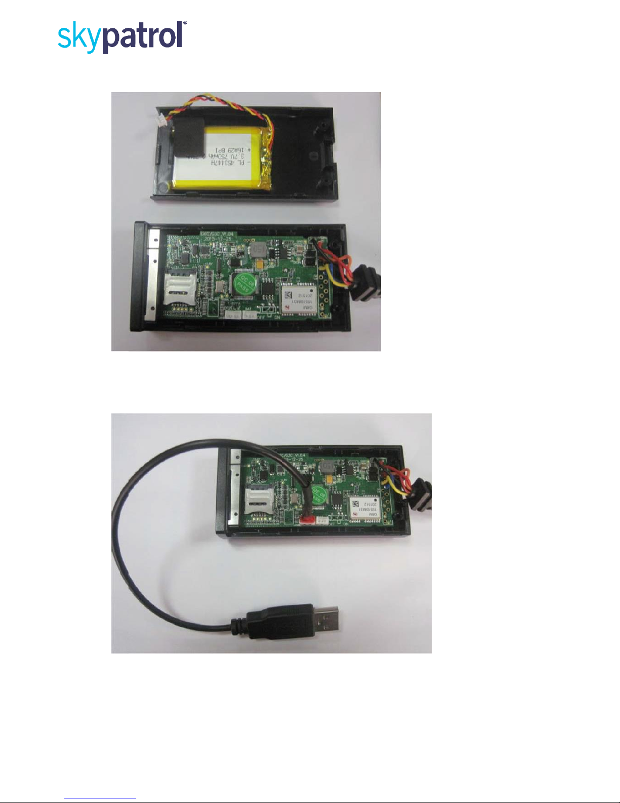
3.2
Open the device cap
(Take G3C US‐3G product for example)
Remove screws in the back of device first. Then force to open the device cap as the
arrow direction.
Remove the device cap carefully.
SP4700s
erie
s products
user manua
10
3.3
Install SIM card
Please note the installation direction of the SIM card.
3.4
Connect USB data line
The USB cable is optional not for standard part, only for se ial interface using.

SP4700s
erie
s products
user manua
11
3.5
Close the case
Put the power connector to corresponding socket and close the case carefully.
Close as the arrow direction and put screws on.

SP4700s
erie
s products
user manua
12
3.6
Installation Direction
Device has built‐in GSM and GPS antenna, the signal of GSM and GPS will be affected
by installation direction of device. The recommended installation direction as follows:
UP

SP4700s
erie
s products
user manua
13
O
4. Interface Definition & Cable Color
Different interface definitions of SP4700 series product explain:
I function
PIN definition
Level d finition
Color
SP2600
SP4700
POWER
VCC
8V‐32V
Red
√
√
GND
8V‐32V
Black
√
√
Digital input
ACC
High level:>5.7V;
Low level:<=5.7V
White
√
√
IN1
High Level:>0.7V
Low Level:<=0.7V
Orange
√
IN2
High Level:>0.7V
Low Level:<=0.7V
Red/Black
√
Digital input
&Analog
input
AD1/IN3
High Level:>6V
Low Level:<=6V
Green
√
AD2/IN4
High Level:>19V
Low Level:<=19V
Blue/ White
√
Digital
output
OUT1
Max open drain
currency:200mA
Blue
√
√
OUT2
Max open drain
currency:200mA
Yellow
√
OUT3
Max open drain
currency:200mA
Brown
Microphone
MIC+
Grey
Speaker
SPK+
Purple
SPK‐
Orange/ white
UART
TXD
TTL
White/ black
√
RXD
TTL
Green/white
√
I‐wire
I‐WIRE
Yellow/ black
√
Note: The number of interface wire is according to the specific product. The color
and definition of the interface wires can find in the above form
5. User Combine Command
Device supports multiple combine commands sent to the device via SMS. The
commands are separated by a comma; the
command is 256 bytes. Formats as below:
maximum length of the combined

SP4700s
erie
s products
user manua
14
User
name
Separated
Comma
Command
1
Separated
Comma
Command
2
Separated
Comma
...
Command
n

SP4700s
erie
s products
user manua
15
1234
,
UNO;139
12345678
,
UPW;
4567
,
...
USP0; 1;24
H;0;W
Command Reply Explanation:
After device received the user's command will immediately process and reply to the
user with SMS, reply SMS has two kinds: command error, command success.
5.1
Command Error SMS
Content
Explanation
G3C V1.00
ERR
Device name, Firmware version
Command Error
5.2
Command Succes SMS
Content
Explanation
G3C V1.00
Device name, Firmware version
UPW:1234
Command Setting
Ext_Pwr=11.94V
External power voltage
BAT=3.90V
Built‐in battery voltage
#3
Consumed messages

SP4700s
erie
s products
user manua
16
6. SMS Report Explanation
There are two kinds of SMS report: interval report and event report, SMS format
have "W" and "T" mode types, GPS and LBS two kinds of p sitioning data.
6.1
“W” Mode Report
Content
Explanation
G3C V1.00
Device name/Firmware version
LTM 2013‐06‐06 14:17:12
Date/Time
http://maps.google.com/maps?q...
Google map hyper link
ETD:28/ACC ON
Event ID/User defined event name/Data
GSM ‐52dBm
GSM network signal strength
EXT_PWR=12.08V
External power voltage
BAT=3.86V
Built‐in battery voltage
#301
Consumed messages

SP4700s
erie
s products
user manua
17
6.2
“T” Mode GPS Report
Content
Explanation
G3C V1.00
Device name/Firmwar version
LTM 2013‐02‐28 23:51:09
Date/Time
GPS 1.55/0.50/3/4
HDOP/ALTITUDE in meter/Fixed satellite
number/Time of first fixed
N23.164302
N means north/S means south
E113.428456
E means east/W means west
SPD:0km/h 0
Speed/Heading
ETD:28/ACC ON
Event ID/User defined event name/Data
GSM ‐52dBm
GSM network signal st ength
EXT_PWR=12.13V
External power voltage
BAT=3.96V
Built‐in battery voltage
#28
Consumed messages

SP4700s
erie
s products
user manua
18
6.3
“T” Mode LBS Report
Content
Explanation
G3C V1.00
Device name/Firmwar version
LTM 2013‐02‐28 23:51:09
Date/Time
MCC/MNC/LAC/CID/RSSI
Base station informati n type
460/0/2503/962C/‐53dBm
Main station(MCC/MNC/Local area code/ Station
ID/Signal strength)
460/0/2731/40F4/‐60dBm
Neighbor station 1
460/0/2703/4050/‐70dBm
Neighbor station 2
ETD:28/ACC ON
Event ID/User defined event name/Data
GSM ‐52dBm
GSM network signal st ength
EXT_PWR=12.13V
External power voltage
BAT=3.96V
Built‐in battery voltage
#28
Consumed messages
Note:
1.
Event report has “Event ID/User defined event name/Data” messages, fixed time
report has not “Event ID/User defined event name/Data” essages.
2.
“Date/Time” message, UTC: Greenwich Mean Time; LTM: Local time zone.

SP4700s
erie
s products
user manua
19
7. Common comm nds
To set your cell phone number as User0 or User1, send SMS command to control and
receive messages from device.
7.1
Set User Cell Phone Number
Command:
UNO command is set up 2 users’ phone numbers; user1 and user2 have the same
authorization. With the correct password, any phone number is able to use this
command. User0’s factory default
password is “1234”.
Command format:
1.
Set user0 phone number:
password is “1234”; User1’s factory default
< User0 Password>, UNO0 ;< new phone number>
2.
Set user1 phone number:
< User1 Password>, UNO1 ;< new phone number>
Parameter description:
<New phone number>: the length is less than or equal 20 bytes. The setting has two
formats:
1.
Domestic phone number, without country code.
2.
International phone number, with country
numbers.
code. It must add “+” before the
Example:
Set user0 phone number:
1234, UNO0; +8613912345678
Or
1234, UNO0; 13912345678

SP4700s
erie
s products
user manua
20
7.2
Set User Password
Command:
UPW command is set user command password. User0’s factory default password is
“1234”; User1’s factory default password is “1234”. Changing the default password at
the first time is highly suggested.
Command format:
1.
Set user0 password:
< User0 Password>, UPW0 ;< New Password>
2.
Set user1 password:
< User1 Password>, UPW1 ;< New Password>
Parameter description:
< New Password>: Fix 4 digits, range is “0000 to 9999”
Example:
Set user0 password
1234, UPW0; 5678
Table of contents
Other Skypatrol GPS manuals

Skypatrol
Skypatrol SP9700 User manual

Skypatrol
Skypatrol SP4600 User manual

Skypatrol
Skypatrol SP2600 User manual

Skypatrol
Skypatrol TT8950 User manual

Skypatrol
Skypatrol ST7200 User manual

Skypatrol
Skypatrol SP1824 User manual

Skypatrol
Skypatrol Evolution User manual

Skypatrol
Skypatrol TT8750 Assembly instructions

Skypatrol
Skypatrol TT8540 User manual

Skypatrol
Skypatrol SP9600 User manual


