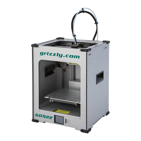
Skytech SkyMaker H Series User manual


Catalogue
Hardware Assembly of Skymaker H Series。
Introduction - 1 -
1. Bottom Corner Fittings Assembly................................................... - 1 -
2. Top Corner Fittings Assembly........................................................ - 8 -
3. Feedmachine Assembly ................................................................ - 14 -
4. Limit Switches Assembly ............................................................. - 18 -
5. Tackles Assembly......................................................................... - 19 -
6. Long Aluminium Fittings Assembly............................................. - 21 -
7. Nozzle Assembly.......................................................................... - 22 -
8. Automatic Level Controller Assembly.......................................... - 25 -
9. Top, Middle and Bottom Components Assembly.......................... - 29 -
10. The Electric Wire Road............................................................... - 31 -
11. Tackles Connect to Automatic Level Controller Assembly......... - 33 -
12. Timing Belt Assembly ................................................................ - 35 -
13. LCD Screen Assembly................................................................ - 37 -
14. Flat Cable on Cardinal Plate Assembly....................................... - 40 -
15. Fix the Cardinal Plate & External Plate Assembly ...................... - 44 -
16. Glass & Feeding Pipe Assembly................................................. - 46 -

- 1 -
Hardware Assembly of Skymaker H Series
First, let us begin by introducing the fittings of Skymaker H Series.
Name
Quantity
Name
Quantity
Hexagon Truss Head Screw
M4*8
2
0.9 ゜step angle with 42
micro-stepping Motor (long
wire)
1
Hexagon Truss Head Screw
M4*10
64
Limit Switches (include wire
& connector post)
4
Hexagon Truss Head Screw
M4*20
3
Cooling Fan
1
Hexagon Cup Head Screw
M2.5*12
8
Nozzle Heated Pipe
1
Hexagon Cup Head Screw
M3*8
21
Nozzle Temperature
Detecting Wire
1
Hexagon Cup Head Screw
M3*12
12
Cardinal Plate
1
Hexagon Cup Head Screw
M3*20
20
LCD Plate
1
Hexagon Cup Head Screw
M5*25
9
Carbon Fiber Shaft (include
plain bearings*2)
6
Hexagon Socket Set
Screw3*4
8
2GT 16 teeth Synchronizing
Wheel
3
M3 Nut
17
Feeding Synchronizing
Wheel
1
M4 Nut
3
F623ZZ Single Side Flange
Bearing
6
M4 Square Nut
64
608ZZ Bearing
1
M5 Nut
27
Rubber Pulley
9
M4 Washer
5
Heating Al Block
1
Bottom Corner Fitting
3
Radiating Al Block
1
Top Corner Fitting
3
Feeding Pipe
1
Automatic Level Controller
A
1
Nozzle 0.4 mm
1

- 2 -
Automatic Level Controller
B
1
Quick Coupler (big)
1
Automatic Level Controller
C
1
Quick Coupler (small)
1
Tackle (include timing belt
connector)
3
2020 Al Fitting (long)
3
Extruder Connector A
1
2020 Al Fitting (short)
9
Extruder Connector B
1
2GT Timing Belt (motor axle
transmission)
1
Limit Switch Stop
3
Coiler
1
Fixing Board of Cardinal
Plate
1
PTFE Pipe
1
LCD Plate Support
2
Round Glass
1
External Plate (power source
& transmission header)
1
USB Line
1
0.9 ゜step angle with 42
micro-stepping Motor (short
wire)
3
DC Stabilized Power Source
1
3P Connector Base
1
2P Connector Base
3

- 3 -
The following are 16 steps for H Series assembly:
1. Bottom Corner Fittings Assembly
2. Top Corner Fittings Assembly -
3. Feeding Machine Assembly
4. Limit Switches Assembly
5. Tackles Assembly
6. Long Aluminum Fittings Assembly
7. Nozzle Assembly
8. Automatic Level Controller Assembly
9. Top, Middle and Bottom Components Assembly
10. The Electric Wire Road
11. Tackles Connect to Automatic Level Controller Assembly
12. Timing Belt Assembly
13. LCD Screen Assembly
14. Flat Cable on Cardinal Plate Assembly
15. Fix the Cardinal Plate & External Plate Assembly
16. Glass & Feeding Pipe Assembly
Now, let’s start to assemble Skymaker H Series!
Bottom Corner Fittings Assembly
Fittings:0.9゜step angle with 42 micro-stepping Motor (short wire)*1、Bottom
Corner Fitting *1、2020 Al Fitting (short) *2、2GT 16 teeth Synchronizing Wheel*1、
Hexagon Socket Set Screw (3*4)*2、M4 Square Nut*10、Hexagon Cup Head Screw
(M3*8)*4、Hexagon Truss Head Screw (M4*10)*10

- 4 -
Assembly:
First, assemble the 2GT 16 teeth Synchronizing Wheel and the 0.9゜step angle with
42 micro-stepping Motor (short wire). Then screw two Hexagon Socket Set Screw
(3*4) on the 2GT 16 teeth Synchronizing Wheel tightly and one of the two Hexagon
Socket Set Screw (3*4) should be screwed on the plane side.
Use Hexagon Truss Head Screw (M4*10) and M4 Square Nut to assemble the two
side with eight holes (M4 Square Nut should be outside) but do not screw them tightly.
They have to be screwed with 2020 Al Fitting (short) later.
In the following picture, use Hexagon Truss Head Screw (M4*10) and M4 Square Nut
to screw two holes. First, put M4 Square Nut on finger and aim at a hole in the
Bottom Corner Fitting. Then use Hexagon Truss Head Screw (M4*10) to screw it
from outside but do not screw them tightly. They have to be screwed with 2020 Al
Fitting (long) later.

- 5 -
In the following picture, these four holes are used to fix the Bottom Corner Fitting and
0.9゜step angle with 42 micro-stepping Motor (short wire).
(the finger-pointed place is the bottom)
Aim at 0.9゜step angle with 42 micro-stepping Motor (short wire) and the Bottom
Corner Fitting. Then use Hexagon Cup Head Screw (M3*8) to screw them tightly.
Assemble 2020 Al Fitting (short) on the same side and then screw Hexagon Truss
Head Screw (M4*10) tightly.

- 6 -
2020 Al Fitting (short) of the three Bottom Corner Fitting should be screwed on the
same side.
Assemble the three Bottom Corner Fitting and put them to be a triangle.
Wedge the three Bottom Corner Fitting to a well-screwed M4 Square Nut. Be careful
not to pinch the wires.
(Wedging them to two well-screwed M4 Square Nut at a time is not acceptable.)

- 7 -
Wedge the three Bottom Corner Fitting to the second well-screwed M4 Square Nut
after finish the first one.
After wedge the M4 Square Nut of three Bottom Corner Fitting well, screw Hexagon
Truss Head Screw (M4*10) tightly.
Now, we finish the assembly of Bottom Corner Fitting!

- 8 -
2. Top Corner Fittings Assembly
Fittings:Top Corner Fitting*1、2020 Al Fitting (short)*1、F623ZZ Single Side Flange
Bearing*2、M4 Square Nut*5、Hexagon Cup Head Screw (M3*20)*1、Hexagon Truss
Head Screw (M4*10)*5、M4 Nut*1、Hexagon Truss Head Screw (M4*20)*1、M3
Nut*1、M4 Washer*1。
Assembly:
Assemble the tackle of timing belt used.
Make Hexagon Cup Head Screw (M3*20) go through the central hole.
Hitch the two F623ZZ Single Side Flange Bearing and stack these two together. The
side with border has to be outside.

- 9 -
Use M3 Nut to screw it tightly.
Assemble the screw of adjusting the tightness of timing belt.
The front and back of Top Corner Fitting

- 10 -
Turn the Top Corner Fitting to the back and put M4 Nut into the six-angled hole.
Press the M4 Nut by finger and turn it to the front to screw M4 Washer and Hexagon
Truss Head Screw M4*20. Be careful not to screw it tightly because it will be used to
adjust the tightness of timing belt later.
Use Hexagon Truss Head Screw M4*10 and M4 Square Nut to assemble two sides
with four holes (M4 Square Nut should be outside). Be careful not to screw them
because they have to be screwed with 2020 Al Fitting (short) later.

- 11 -
In the following picture, we have to use Hexagon Truss Head Screw (M4*10) and M4
Square Nut. Assemble Hexagon Truss Head Screw (M4*10) toward outside. First, put
M4 Square Nut on finger and aim at the hole in the Bottom Corner Fitting and use
Hexagon Truss Head Screw (M4*10) to screw from outside. Be careful not to screw it
tightly because it will be screwed with 2020 Al Fitting (long) later.
Assemble 2020 Al Fitting (short) and screw the Hexagon Truss Head Screw (M4*10)
tightly.
2020 Al Fitting (short) of the three Top Corner Fitting should be screwed on the same
side.

- 12 -
Put the three Top Corner Fitting to a triangle.
Wedge the three Top Corner Fitting to a well-screwed M4 Square Nut.
(Wedging them to two well-screwed M4 Square Nut at a time is not acceptable.)

- 13 -
Wedge the second well-screwed M4 Square Nut after finish the first well-screwed M4
Square Nut with the three Top Corner Fitting.
After wedge the M4 Square Nut of three Top Corner Fitting well, screw Hexagon
Truss Head Screw (M4*10) tightly.
Now, we finish the assembly of Top Corner Fitting!

- 14 -
3. Feeding Machine Assembly
Fittings:0.9゜step angle with 42 micro-stepping Motor (long wire)、Extruder
Connector A*1、Extruder Connector B*1、Feeding Synchronizing Wheel*1、Hexagon
Socket Set Screw (3*4)*1、Hexagon Truss Head Screw (M4*10)*2、Hexagon Truss
Head Screw (M4*8)*1、Hexagon Cup Head Screw (M3*8)*3、M4 Washer*1、608ZZ
Bearing*1、M4 Square Nut*2、Hexagon Cup Head Screw (M3*12)*1、Hexagon Cup
Head Screw (M3*20)*1、M3 Nut*2、Quick Coupler (small)*1。
Assembly:
Assemble 0.9゜step angle with 42 micro-stepping Motor (long wire) and Extruder
Connector A and then use three Hexagon Cup Head Screw (M3*8) to screw them
tightly.
In the following picture, the three holes are used to be screwed with Hexagon Cup
Head Screw (M3*8).
Use Hexagon Cup Head Screw (M3*12) to screw the Extruder Connector B.
In the following pucture, the hole is used to be screwed with Hexagon Cup Head
Screw (M3*12).

- 15 -
Assemble 608ZZ Bearing and Feeding Synchronizing Wheel and then use Hexagon
Socket Set Screw(3*4) to screw tightly.
Hexagon Socket Set Screw(3*4) has to be screw on the plane side.
Use M4 Washer and Hexagon Truss Head Screw (M4*8) to prevent 608ZZ Bearing
falling.

- 16 -
In the following picture, put a M3 Nut into the hole.
Assemble Hexagon Cup Head Screw (M3*20) and a M3 Nut and then screw. Then
screw the M3 Nut at the hole.
(The shorter the distance between two M3 Nut is, the tighter the feeding machine
fasten the filament.)
Screw the Quick Coupler (small) tightly.

- 17 -
Put two M4 Square Nut into the guide on the Al Fitting.
Use two Hexagon Truss Head Screw M4*10 to fix the Feeding Machine and we are
done with the assembly of Feeding Machine!
Advise you to screw it near the 2020 Al Fitting (long) of Top Corner Fitting to prevent
the motor line from exposing on the outside.

- 18 -
4. Limit Switches Assembly
Fittings:Limit Switches (include wire & connector post)、Limit Switch Stop*1、2P
Connector Base*1、M4 Square Nut*1、Hexagon Truss Head Screw (M4*10)*1、
Hexagon Cup Head Screw (M2.5*12)*2。
Assembly:
The front and the back of Limit Switch Stop.
Make Hexagon Truss Head Screw (M4*10) go through from the front and M4 Square
Nut is screwed on the back side.
Use Hexagon Cup Head Screw (M2.5*12) screw the Limit Switches (include wire &
connector post) on the front side.
Table of contents
Other Skytech 3D Printer manuals
