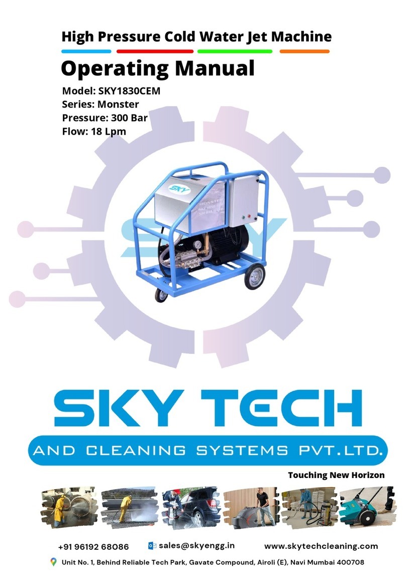
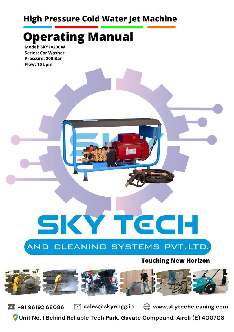
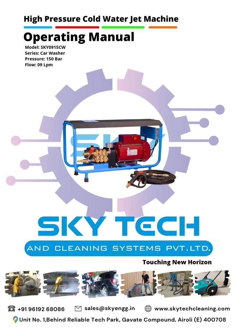
Skytech SKY1315CW User manual

High Pressure Cold Water Jet Machine
Operating Manual
Touching New Horizon
+91 96192 68086 sales@skyengg.in
Unit No. 1,Behind Reliable Tech Park, Gavate Compound, Airoli (E) 400708
www.skytechcleaning.com
Model: SKY1315CW
Series: Car Washer
Pressure: 150 Bar
Flow: 13 Lpm

1. INDTRODUCTION
The horizontal Plunger Pumps are designed and manufactured to pump or transfer
are generally driven by: electric
motors,
motors, tractor P.T.O...
Couplings may be fulfilled
flanging, reduction unit or
multiplier,
The Pumps are supplied
standard
Pump from the head (see fig.1).
On
on the left.
The Pump is supplied to be installed on a more complex machine or plant; the
manufacturer of such
machine
the
assembled machine/plant
2. INTENDED USE
Plunger Pumps are designed to be used in machines or systems for transferring pressurized water,
such as the following for example:
Bin Washers, Water Treatment,
Misting,
The temperature of the
workplace
The Pump cannot be used
submerged
3. OPERATIONAL RESTRICTION
The specifications of the liquid to
be
liquids; in particular, it is NOT
possible
In the
presence
for this
type
In
workplaces
In the
presence
material
To
pump
ATEX
workplaces).
To
foodstuffs.
To
wash
To
wash
4. GENERAL WARNING
Never start the
Pump
Constantly check
the
under pressure.
Pipes
shall be
replaced.
The Pump must
never
Protect rotating
parts
The Pump is
designed
systems, which may make the noise level vary, even quite substantially. The manufacturer of
such machine or
system and
inform
Protection
equipme
5. BEFORE START UP
LIQUIDS TO BE
PUMPED
The Pump is designed and
manufactured
The liquid in taken must be free
from
The liquid in taken shall have
viscosity
The maximum temperature of
the liquid to be pumped varies according to the conditions of the
system (see section 6.3 - INLET
Any other use is not admitted
unless
INLET AND
OUTLET OF
The Inlet port for the liquid that
must
The horizontal Plunger Pumps are designed and manufactured to pump or transfer
water.
motors,
endothermic petrol or diesel engines and
hydraulic
Couplings may be fulfilled
by means of transmission
shaft, direct
multiplier,
joints, pulleys and belts.
standard
with the power take-off of the shaft on the right,
looking
On
request, all Pump models can be supplied with
power
The Pump is supplied to be installed on a more complex machine or plant; the
machine
or plant shall add all the information related
to
assembled machine/plant
fulfilled.
Plunger Pumps are designed to be used in machines or systems for transferring pressurized water,
Car Wash, Civil and Industrial Washing Systems, Road
Washers
Misting,
Drain and Pipe Cleaning and Fire-fighting.
workplace
shall be between: Min. 0°C (32°F) - Max.45°C (113°F)
submerged
under any type of liquid.
be
used are described in detail herewith: do not use for
different
possible
to use Pumps in the following conditions:
presence
of water with high salt content, such as seawater
for
type
of use, you are recommended to use Pump stainless
steel
workplaces
where there is a corrosive or explosive atmosphere.
presence
of any liquid that is not compatible with the
constructional
of the Pump.
pump
paint, solvents, fuel and any flammable liquid (not
suitable
workplaces).
foodstuffs.
wash
people, animals, live electrical or electronic equipment.
wash
the Pump itself.
Pump
under pressure.
the
state of wear of the pipes and relevant fittings,
especially
Pipes
with signs of abrasion or that do not guarantee a
perfect
replaced.
never
run dry/without any liquid while in use.
parts
with a cover to prevent contact..
designed
to be integrated in a machine or system,
with
systems, which may make the noise level vary, even quite substantially. The manufacturer of
or
system shall assess the level of noise emitted by the
assembled
inform
the user appropriately, also in relation to the use
of
equipme
n t .
PUMPED
manufactured
to transfer clean liquid or non-aggressive watery
solutions.
from
sand or other solid particles in suspension.
viscosity
and density similar to water.
the liquid to be pumped varies according to the conditions of the
CONDITIONS).
unless
authorized in writing by the Engineering Department of
SKY
OUTLET OF
THE PUMP
must
be pumped is generally located on the lower part of
the
water.
They
hydraulic
shaft, direct
looking
at the
power
take-off
The Pump is supplied to be installed on a more complex machine or plant; the
to
safety of
Plunger Pumps are designed to be used in machines or systems for transferring pressurized water,
Washers
and
different
for
example;
steel
series.
constructional
suitable
for
especially
those
perfect
seal
with
various supply
systems, which may make the noise level vary, even quite substantially. The manufacturer of
assembled
machine or
of
suitable personal
solutions.
the liquid to be pumped varies according to the conditions of the
SKY
.
the
Pump's

head and may also be called the
suction
generally located on the upper
part
The Inlet and outlet ports may
be
dismantling or inverting
the closure
The Inlet and Outlet
CANNOT
INLET
CONDITIONS
Pump
is
mounted
abovethe
supply tank.
Max. difference of level
between
Pump and supply tank:
0,5 m/1.6 ft.
Max. working pressure:150
bar (2200 PSI).
Max inlet vacuum:
-0.2 bar (-6 inch.Hg).
Max. Pump speed: 1450 RPM.
Max.
Inlet
water
temperature:
40°C (104°F).
The inlet pipeline must comply
with
-
Any point of the inlet
pipeline cannot
-
Be absolutely leak-proof to
avoid
-
Not have 90° bends near the
Pump
-
Not have contractions or
restrictions.
-
Avoid any turbulence near
the
-
If an inlet filter is used, it must
cause any
contraction or any pressure drop. The filter should be grant a filtration degree between 50
and 80 meshes and should be
cleaned
Any other use is not admitted
unless
OUTLET
CONDITIONS
Make sure the delivery line and all the accessories are connected correctly, secured firmly, hermetically
that the pipes are sized appropriately. All pressurized pipes must be
pressure, which must never be less
than
SPEED AND
ROTATION
The rotation
speed
of the actual
Pump.
The minimum RPM admitted
The rotation direction of the
shaft
suction
port or supply port. The Outlet port for the
pumped
part
of the head and may also be called the delivery port.
be
used either on the right or the left side of the
Pump's
the closure
plugs.
CANNOT
be inverted.
CONDITIONS
(SUCTION)
abovethe
Pump is mounted below
the supply tank in gravity
feeding.
Pump is
pressure
between
Max. Pump speed: 1750 RPM.
Max. Inlet
pressure:6
bar (90 PSI).
Max. inlet water
temperature up to 150
Bar
The feeding source must
provide 50% more
than
Pump flow.
(2200 PSI) of
Working pressure: 50°C
(122°F).
If a pressure
feeding
used, it must be
started
the plunger Pump.
Max.
Inlet
water
temperature
over to 150 bar (2200 PSI) of
working pressure: 35°C
Max.
Inlet
water
temperature:
50°C (122°F).
(95°F).
with
the following requirements:
pipeline cannot
be smaller than the diameter of the Pump inlet.
avoid
any air infiltration
Pump
inlet.
restrictions.
the
Pump inlet and in the supply tank.
allow 200% more flow than the flow required by the
Pump.
contraction or any pressure drop. The filter should be grant a filtration degree between 50
cleaned
on a regular basis to ensure its proper
functionality.
unless
authorized in writing by the Engineering
Department
CONDITIONS
Make sure the delivery line and all the accessories are connected correctly, secured firmly, hermetically
that the pipes are sized appropriately. All pressurized pipes must be
marked durably with the
maximum
than
the maximum working pressure of the Pump, written on
the Label
ROTATION
DIRECTION
speed
of the shaft of the Pump must never exceed the RPM
written
Pump.
is: maximum RPM x 0.6.
shaft
of Pumps may be clockwise or anticlockwise.
pumped
liquid is
Pump's
head, by
pressure
fed.
pressure:6
The feeding source must
than
the
feeding
Pump is
started
before
temperature:
Pump.
It must not
contraction or any pressure drop. The filter should be grant a filtration degree between 50
functionality.
Department
of SKY.
Make sure the delivery line and all the accessories are connected correctly, secured firmly, hermetically
sealed and
maximum
admitted
the Label
written
on the Label

6. CONTROLS ON SYSTEM
UNLOADER
VALVE
A pressure regulator valve must
indicated on the Label of the
Pump.
Use of the Pump, even
for
the Pump itself.
The regulator valve shall be
compatible
values written on the Label and in
Incorrect installation of the pressure regulator valve could cause serious personal injuries and
damage to property as
well
The circuit must be
equipped
being exceeded in the
case
NOZZLE
A deteriorated nozzle could
cause
valve in the attempt to increase the pressure of the system because when the delivery line closes, this
would cause a boost in
pressure, which
If the pressure
drops, it is advisable to replace the nozzle and adjust the system's pressure again. The
flow rate of the Pump must be
at least
excess flow rate must
be discharged.
PULSATION
DAMPENER
For applications in which pulses produced by the Pump on the delivery line are harmful or undesired,
install an appropriately sized
pulse
PRESSURE
GAUGE
Install a gauge as near as possible to the outlet of the Pump because the
on the Pump's Label refers to the
pressure
on other accessories.
All the components of
the
An example of
the diagram
a Circuit
VALVE
be installed to avoid the pressure exceeding the
maximum
Pump.
for
a short period, with a pressure higher than such limit
would
compatible
with the maximum pressure, flow rate and
temperature
the "INLET CONDITIONS".
Incorrect installation of the pressure regulator valve could cause serious personal injuries and
well
as seriously damaging the actual Pump.
equipped
with another safety valve to prevent the maximum
pressure
case
of anomalies in the pressure regulator valve.
cause
a drop in pressure; in this case, do not adjust the
pressure
valve in the attempt to increase the pressure of the system because when the delivery line closes, this
pressure, which
could damage the Pump.
drops, it is advisable to replace the nozzle and adjust the system's pressure again. The
at least
10% higher than
the
flow rate that
the
utilities
demand; the
be discharged.
DAMPENER
(ACCUMULATOR)
For applications in which pulses produced by the Pump on the delivery line are harmful or undesired,
pulse
dampener.
GAUGE
Install a gauge as near as possible to the outlet of the Pump because the
maximum pressure written
pressure
detected on the head of the Pump and not on
the
the
machine or of the circuit must have technical
specifications
An example of
the diagram
of
a Circuit
maximum
limit
would
damage
temperature
Incorrect installation of the pressure regulator valve could cause serious personal injuries and
pressure
from
pressure
regulator
valve in the attempt to increase the pressure of the system because when the delivery line closes, this
drops, it is advisable to replace the nozzle and adjust the system's pressure again. The
demand; the
For applications in which pulses produced by the Pump on the delivery line are harmful or undesired,
maximum pressure written
the
nozzle or
specifications
compatible

with the data written on
the
7. INSTALLATION, START UP AND
SWITCHING
POSITIONING
Smaller and lighter Pumps can be handled by hand in compliance with current standards. Heavier
Pumps must be handled using the dedicated hook and
you need to use a lifting device, use appropriate strap/s, being careful not to damage the product. The
weight of the Pumps is written in
the
If the Pump is used in particularly dirty
recommended to
protect it, respecting
ASSEMBLY
Fit the Pump on a rigid surface keeping the power take
correct drainage in the
case of leakage of water or oil. The Pump must be secured firmly on a base,
which must be perfectly aligned with the transmission components. In the case of belt transmission,
make sure the pulleys are aligned
Use
appropriately sized hoses, both on the inlet and outlet of the Pump, according to the technical
specifications written on the
Label.
START UP
Before starting, check the
following:
Replace the RED cap
on
accessories supplied.
Check the oil level
through
Check the pressure
value
The pressure regulator
valve
Start and run the Pump for approximately 10 seconds until all the liquid has discharged from the
delivery line. Once the intake cycle is complete, you can set the Pump at the required pressure, by
adjusting the pressure
regulator valve, without ever exceeding the maximum pressure written on the
Pump's Label.
SWITCHING OFF
After use or if the Pump is to be put away in storage, wash it internally. You can do this by running the
Pump for several minutes with
clean water, then disconnect the supply line and leave the Pump to run
for approximately 15 seconds so
that
A few minutes devoted to the
internal
pump's lifetime.
Do not wash the Pump externally: water could get into the Pump crankcase, for example
through the oil vent cap.
After switching off, the
Pum
Do not throw the liquid
used
PRECAUTIONS
AGAINST
If shutdown during winter or in the case of places and seasons subject to frost, once the Pump has
finished working, run it for the time required to pump an emulsion of 50% of clean water and
antifreeze fluid through it in order
to prevent freezing
The Pump must not be used to
Pump
In the presence of ice or very
cold
started; otherwise the Pump
could
completely defrosted.
the
Pump's Label.
SWITCHING
OFF
Smaller and lighter Pumps can be handled by hand in compliance with current standards. Heavier
Pumps must be handled using the dedicated hook and
suitable lifting device. If there is no eyelet and
you need to use a lifting device, use appropriate strap/s, being careful not to damage the product. The
the
table on page 25.
If the Pump is used in particularly dirty
workplaces or is exposed to atmospheric agents, you are
protect it, respecting
the ventilation conditions.
Fit the Pump on a rigid surface keeping the power take
-
off and support feet horizontal to ensure
case of leakage of water or oil. The Pump must be secured firmly on a base,
which must be perfectly aligned with the transmission components. In the case of belt transmission,
and check the tension of the belts.
appropriately sized hoses, both on the inlet and outlet of the Pump, according to the technical
Label.
following:
on
the Pump Crankcase with the venting cap in the
through
the dedicated oil reservoir or inspection cap; top-up if
necessary.
value
on the accumulator, if installed; inflate or deflate if
necessary.
valve
must be set at "0" pressure to favour intake.
Start and run the Pump for approximately 10 seconds until all the liquid has discharged from the
delivery line. Once the intake cycle is complete, you can set the Pump at the required pressure, by
regulator valve, without ever exceeding the maximum pressure written on the
AND STORAGE
After use or if the Pump is to be put away in storage, wash it internally. You can do this by running the
clean water, then disconnect the supply line and leave the Pump to run
that
all the water in the head is discharged.
internal
washing of the pump brings considerable benefits in
terms
Do not wash the Pump externally: water could get into the Pump crankcase, for example
Pum
p could remain very hot for some time.
used
to wash the Pump outdoors but observe current
standards.
AGAINST
FREEZING
If shutdown during winter or in the case of places and seasons subject to frost, once the Pump has
finished working, run it for the time required to pump an emulsion of 50% of clean water and
to prevent freezing
and damage to the Pump.
Pump
antifreeze fluid that is not mixed with water.
cold
temperatures at the workplace, the Pump must
never
could
be seriously damaged. To start the system, the whole
circuit
Smaller and lighter Pumps can be handled by hand in compliance with current standards. Heavier
suitable lifting device. If there is no eyelet and
you need to use a lifting device, use appropriate strap/s, being careful not to damage the product. The
workplaces or is exposed to atmospheric agents, you are
off and support feet horizontal to ensure
case of leakage of water or oil. The Pump must be secured firmly on a base,
which must be perfectly aligned with the transmission components. In the case of belt transmission,
appropriately sized hoses, both on the inlet and outlet of the Pump, according to the technical
kit of
necessary.
necessary.
Start and run the Pump for approximately 10 seconds until all the liquid has discharged from the
delivery line. Once the intake cycle is complete, you can set the Pump at the required pressure, by
regulator valve, without ever exceeding the maximum pressure written on the
After use or if the Pump is to be put away in storage, wash it internally. You can do this by running the
clean water, then disconnect the supply line and leave the Pump to run
terms
of the
Do not wash the Pump externally: water could get into the Pump crankcase, for example
standards.
If shutdown during winter or in the case of places and seasons subject to frost, once the Pump has
finished working, run it for the time required to pump an emulsion of 50% of clean water and
50% of
never
be
circuit
must be

8. MAINTENANCE
ROUTINE
MAINTENANCE
If the Pump is used for light-duty
purposes,
After the first 50 hours:
Oil
Every 200 - 300 hours:
Oil
Every 1000 hours:
Replace
rings for heavy-duty
purposes,
jobs more often.
When inspecting or
replacing
caps over the valves (see
LUBRICATION
The Pump is supplied with the
correct
Periodically check the oil level in
the
Use OIL type SAE 15W-40 or
equivalent.
BRAND
AGIP
BP
CASTROL
ESSO
MOBIL
SHELL
TOTAL
The oil is to be changed by
draining
Pump stopped.
Every time you unscrew the oil
drain
DO NOT START
THE
During
maintenance,
Use and wear suitable personal protection equipment (i.e.
gloves). Wait
for
stopped
completely.
During
maintenance,
If the Pump is to
be
1.
Separate the
various
metal etc.).
2.
Use public or
dispose of
waste.
3.
This device
could
disposal could
have
MAINTENANCE
purposes,
the following routine maintenance jobs are
advised:
Oil
change (see section 9.2 - Lubrication)
Oil
change (see section 9.2 - Lubrication)
Replace
the valves - replace piston seal
purposes,
carry out the maintenance
replacing
the Pump valves, be careful which type of Loctite®
you
table on page 26-27).
correct
amount of lubrication oil (see table on page 25).
the
Pump through the oil level indicator.
equivalent.
Here are some recommended types of oil:
TYPE
F.1 Supermotoroil 20W-40
Vanellus C 20W-40
CASTROL
GTX 20W-40
Uniflo 20W-40
Super M 20W-40
Rimula R4 20W-40 / Helix Super
20W40
Rubia 20W-40 / Quartz 5000 20W-40
draining
it through the dedicated bottom oil drain plug and strictly
drain
plug we suggest replacing its gasket
THE
PUMP IF THERE IS NO OIL IN THE PUMP!
maintenance,
you are recommended to:
Use and wear suitable personal protection equipment (i.e.
for
the machine to cool down and to have
completely.
maintenance,
d not throw residues outdoors but observe current
standards.
be
scrapped:
various
parts depending on their type (i.e. plastic,
harmful
private waste disposal systems envisaged by local law
to
waste.
could
contain harmful substances: improper use or
incorrect
have
negative effects on human health and on the
environment.
advised:
you
use on the
with the
standards.
harmful
fluids,
to
incorrect
environment.

PROBLEMS
PROBABLE CAUSES
SOLUTIONS
The Pump
doesn’t
reach
required
pressure.
Incorrect or worn or plugged nozzle.
Change
to
proper
size
nozzle;
replace nozzle or clean nozzle.
Belt
slippage.
Tighten
or
replace
belt.
Air
leak
in
inlet
plumbing.
Check
or
replace
hoses
or
fittings.
Inlet
suction
strainer
clogged
or
improper size.
Check and clean, use adequate size.
Worn
seals.
Abrasives in Pumped fluid; severe
cavitations; inadequate
water supply.
Install and maintain proper filter.
Replace seals. Check inlet supply:
Max. -0,2 bar (-6 inch.Hg) vacuum.
Pressure
gauge
is
broken
or
not
registering accurately.
Check
with
new
gauge;
replace
worn
or
damaged
gauge.
Relief / unloader
valve stuck,
partially plugged or improperly
adjusted.
Adjust
or
repair
or
replace
relief / unloader valve.
Dirty
or
worn
inlet
or
outlet
valves.
Check
and
clean
or
replace
valves.
Leaky outlet hose.
Check
or
replace
discharge hoses
or
fittings.
Pump is noisy.
Air
leak
in
inlet
plumbing.
Check
or
replace
hoses
or
fittings.
Inlet
strainer
clogged
or
improper
size or insufficient supply of water to
the
Pump.
Check and clean, use adequate
size; increase water supply if not
sufficient.
Dirty
or
worn
inlet
or
outlet
valves.
Check
and
clean
or
replace
valves.
Worn
seals
or
o
-
rings.
Replace
seals
or
o
-
rings.
Plugged
inlet
filter or
improper
size.
Clean
or replace
filter.
Pulley
loose
on
crankshaft
or
worn
key.
Check
pulleys
and
key.
Broken
or
worn
bearings.
Replace
bearings.
Water
leakage
underthe
Pump
head.
Worn
low
pressure
seal
or
o
-
ring.
Replace
seal
or
o
-
ring.
Cracked
plunger.
Install
new
plunger.
Water in
crankcase. Oil
is
changing
colo
r into white.
High humidity in air (condensing).
Change
oil
every 250
hours
instead of
500.
Worn
crankcase
oil
seal.
Replace
crankcase
oil
seal.
Worn
low
pressure
seal.
Replace
seal.
Oil leak
between
crankcase and
head.
Worn crankcase oil seal.
Check plunger rod.
Replace crankcase oil
seal.
Oil leak in
the area of
crankshaft.
Worn
crankshaft
oil
seal.
Replace
crankshaft
oil
seal.
Worn
bearing
case
o
-
ring.
Replace
bearing
case
o
-
ring.
Bad
bearings.
Replace
bearings.
Oil leak at the
reared of the
Pump.
Damaged
or
improperly
installed
sight glass or crankcase cover seal or
drain plug.
Replace sight glass, plug or seals.
Frequent
or
premature
failure of
the
packing.
Scored
plungers.
Replace
plungers.
Over
pressure
in
inlet
manifold.
Reduce
inlet
pressure.
Abrasive
material
in
the
fluid
being Pumped.
Install proper filter
on
Pump
inlet
plumbing.
Corrosive additives in the fluid
being Pumped.
Use clean water or contact SKY
Technical Service Department for
more information’s.
Excessive
temperature
of
fluid
being Pumped.
Assure fluid inlet temperature
are within specified range (see
page
20).
Running
Pump
dry.
Do
not
run
Pump
without
fluid.
Excessive
vibrations
in outlet
line.
Air
leak
in
inlet
plumbing.
Check
or
replace
hoses
or
fittings.
Pulsation
damper
pressure
too
low.
Check
and
repressure.
Dirty
or
worn
inlet
or
outlet
valves.
Check
and
clean
or
replace
valves.
9. TROUBLE SHOOTING


DENOMINAZIONE - TITLE
CODICE - PART NO. REV.
MV925 G 3/8 F - G 1/4 F Campelli
15/03/13
4012205000 0
VIETATO RIPRODURRE O DIVULGARE IN TOTO O IN PARTE IL PRESENTE
DISEGNO SENZA AUTORIZZAZIONE SCRITTA DELLA TECOMEC S.p.A.
IT IS FORBIDDEN TO PARTIALLY OR TOTALLY COPY, USE OR DISCLOSE THIS MATERIAL
WITHOUT PRIOR WRITTEN CONSENT FROM TECOMEC S.p.A.
DWN
DISEGN.
VISTO
APPROVED
DATA
DATE
RF
CODICE CLIENTE - CUSTOMER PART NO.
42124- REGGIO EMILIA - ITALY
1
2
3
4
5
6
8
11
14
19
KIT 1 - KIT RICAMBI SE E GUARNIZIONI - REPAIR KIT SEAT GASKET Cod. 4019900025
KIT 2 - KIT RICAMBI LEVA COMPLETA - REPAIR KIT TRIGGER Cod. 4019900026
KIT 3 - KIT RICAMBI SCOCCHE E VITI - REPAIR KIT SHELL SCREW Cod. 4019900029
Num. Codice escrizione Completa Quant. Kit1 Kit2 Kit3
1 C00015011 CORPO MV925 G 1/4 F 1
2 000117 A.A. 3,00x 7,40x1,30 TB 1 X
3 060143 GUOR 2.62X2.84 104 VITON 75 NERO 1 X
4 R00300014 RON ELLA 3 X 7 X 1,5 OTTONE 1 X
5 P00004004 PERNO PREMISFERA MV925 1 X
6 0106200140 SE E MV2001 CONIATA CON OR NBR 90 1 X
7 160013 SFERA 5/16 G28 AISI 420C HRC 56 MIN 1 X
8 M00201052 MOLLA INOX 1,7 X 9,4 X 16,5 1
9 0110750700 GUOR 1.5X11 NBR 90 NERO 1 X
10 T00000096 TAPPO MV 925 VERS. STAN AR 1
11 T00303044 TUBO L.130 MM ZINCATO G 1/4 M 1
12 R00000212 RACCOR O ENTR. OTT G 3/8 F 1
13 L00002049 LEVA MV 925 NERA 1 X
14 P00004005 PERNO PER LEVA MV925 .4X22 INOX 1 X
15 P00000087 PERNO PER LEVA MV925 .5X33 IX 1 X
16 0100740520 SICURA MV951- ROSSA - 1 X
17 S02301247 SCOCCA MV 925 ESTRA NERA 1 X
18 T00200169 TARGHETTA MV 925 ESTRA ROSSA 1 X
19 S02301248 SCOCCA MV 925 SINISTRA NERA 1 X
20 0116730010 VITE AUTOF. 4 X 19 UNI 9707 6 X
21 T00200170 TARGHETTA MV 925 SINISTRA ROSSA 1 X
15
BETTAGLIO- ETAIL B
A
ETTAGLIO- ETAIL A
20
9
10
18
13
21
17
12
7
16

DENOMINAZIONE - TITLE
CODICE - PART NO. REV.
VRT3 G 3/8 F 31 MPA + MANOPOLA
0215010260 3
VIETATO RIPRODURRE O DIVULGARE IN TOTO O IN PARTE IL PRESENTE
DISEGNO SENZA AUTORIZZAZIONE SCRITTA DELLA TECOMEC S.p.A.
IT IS FORBIDDEN TO PARTIALLY OR TOTALLY COPY, USE OR DISCLOSE THIS MATERIAL
WITHOUT PRIOR WRITTEN CONSENT FROM TECOMEC S.p.A.
CODICE CLIENTE - CUSTOMER PART NO.
42124- REGGIO EMILIA - ITALY
9
15
17
1
12
13
23
9
7
15
22
14
26
27
25
KIT RICAMBIO VRT3 31 MPa Co . 4079900005
Num. Co ice Descrizione Completa Quant. Kit
1 0109712650 CORPO VRT3 G 3/8 F MV 0316 01B 1
3 4079500001 SEDE VRT3 Ø8 CONIATA CON OR NBR 90 1 X
4 0112720010 SFERA DIAM.13/32 AISI 44OC TEMP G20 1 X
5 0107720820 MOLLA SFERA MV 0316 28 1
6 0110751311 GUOR 1.78X17.17 2068 NBR 90 NERO 2 X
7 0115712280 RAC.SEDE3/8GF SF13/32' MV 0316 15A 1
8 0104720230 STELO VRT3 MV 0316 04 1
9 000125 A.A.11,50x15,9x1,20 TBT 000125B 2 X
10 0110750910 GUOR 2.62X10.78 3043 NBR 70 NERO 1 X
11 0110750170 GUOR 2.62X7.6 3030 NBR 70 NERO 1 X
12 0122790030 A.A.8X12,6X1,2 MV 0316 05 1 X
13 0115712250 RAC.GUIDA STELO VRT3 MV 0316 06 1
14 0118720120 SPINA ELASTICA UNI ISO 28748 3X14 1
15 030200 DADO VRTVHP M 8 x 4 OTT. 2
16 0107770080 MOLLA 5,7X20,7X56 31 MPA MV 0316 19 1
17 150204 RONDELLA D. 8,5x24,0x2,0 Z.B. 1
18 400305 MANOPOLA VRT2VHP ROHS 1
19 030101 DADO AUTOBLOC.BASSO M8x8 Z.B. 1
20 0128740090 COPERCHIO MAN.31MPA MV 0316 22 1
21 060109 GUOR 3.0X6.0 NBR 90 NERO 1 X
22 0157710040 OTTURATORE VRT3 MV 0316 07 1
23 0107720800 MOLLA OTTURATORE VRT3 MV 0316 08A 1
24 0110751321 GUOR 1.78X15.6 2062 NBR 90 NERO 1 X
25 0115712260 RACCORDO RITEGNO G3/8 F 1
26 060200 GUARNIZIONE D.14 x8,3x1,5 RAME 2
27 170101 TAPPO E.I. G3/8 CILINDRICO OTTONE 2
26
27
6
11
10
5
6
21
24
19
18
20
3
4
16
8
Table of contents
Other Skytech Pressure Washer manuals
Popular Pressure Washer manuals by other brands

Fieldmann
Fieldmann FDW 201402-E operating instructions

Nilfisk-Advance
Nilfisk-Advance E130.3 X-TRA Repair manual

Comet
Comet KT 1750 extra instruction manual
A.R.North America
A.R.North America AR388 Operating instructions and parts list
Parkside
Parkside PDR 12 A1 Translation of the original instructions
DeWalt
DeWalt DPD3000IC instruction manual
