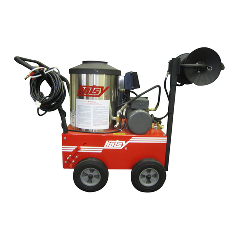
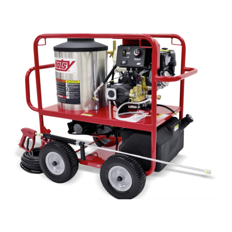
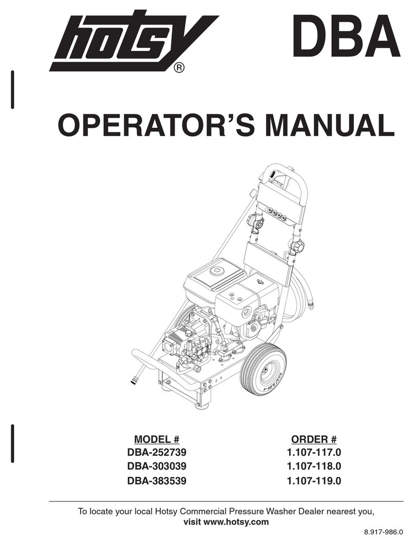
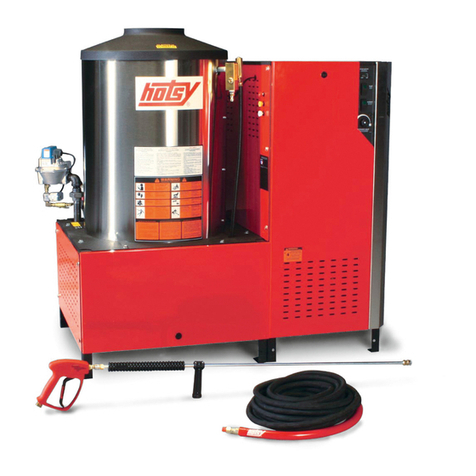
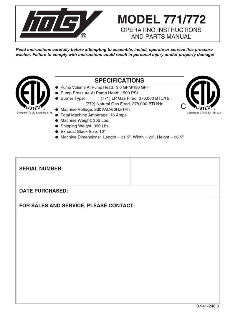
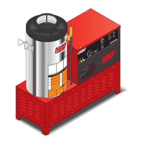
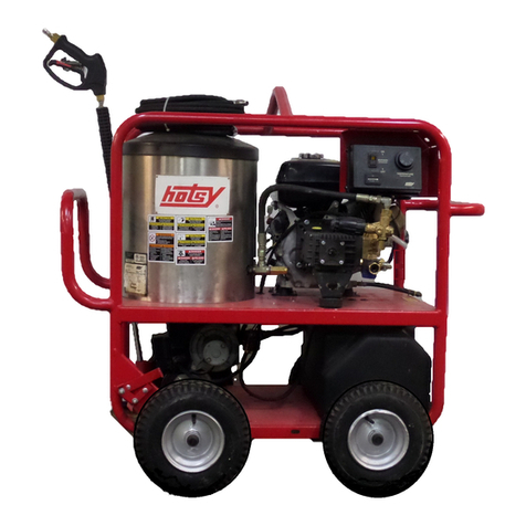
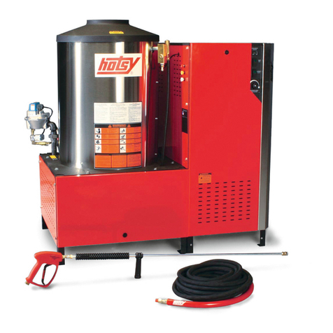
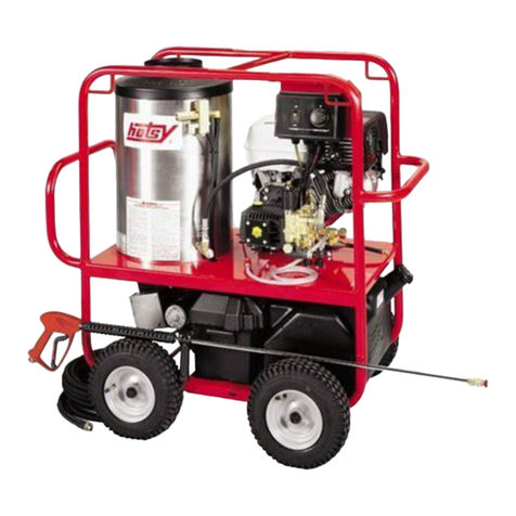
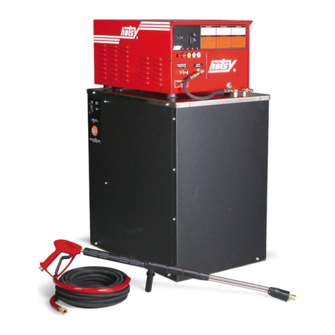
Hotsy 555 HE User manual

9.808-216.0 English Rev B (01/21) 1
555 HE
Service Manual

9.808-216.0 English Rev B (01/21) 2
Preface
Safety instrucons
Hazard levels
Descripon in this service manual
Service groups
Technical Features
Intended use
Field of applicaon
Safety installaons
Connecon performance of appliance
Pump
Safety catch
Unloader / bypass valve
Thermal relief valve
Symbols on the machine
Type plate
Flow paern
Overview of the appliance
Callouts 555 HE
Pump overview
Pump head overview
Pump head cross secon overview
Pump breakdown overview
Unloader / Bypass valve overview
Thermal relief valve overview
Fuel pump
High-eciency burner
Fuel nozzle
Burn head assembly
Measure fuel consumpon (only for California)
Service group
Scheduled maintenance chart
Trouble shoong chart
Trouble shoong process
Understanding the dierence between low, cavitaon and pulsang pressure
Pulsaon
Contents
5
5
5
6
6
6
6
6
6
6
6
7
7
7
7
7
8
9
9-10
11
11
11
12
13
13
14
14
15
15
15
16
16
17
18
18
18

9.808-216.0 English Rev B (01/21) 3
Cavitaon
Low pressure
Replacing leaking thermal relief valve
Vibraon
Water leaking from under pump
Oil is leaking from under pump
Oil is milky
Pressure washer unloader cycles when trigger or spray bar trigger is released
Motor will not turn on
Machine shuts o aer running a while
No burner
Burner motor turns on but there is no ame—fuel
Raw fuel out of burner exhaust
Burner ame turns on but low water temperature
Water temperature is too hot
Scheduled maintenance acvies
Inspecng pump oil
Changing pump oil
Changing quick connects / O-rings
Burner fuel lter—drain water / clean / replace
Cleaning hard water deposits from heang coils
Cleaning soot deposits from heang coils
Fuel nozzle replacement
Trouble shoong acvies
Check valve inspecon / replacement
Inspect packings, ceramic pistons and connecng rod connecon
Inspect inlet screen
Bypass thermal protector
Test pressure at trigger gun
Test pressure o the machine
Test pressure o the coil outlet
Test pressure before the coil inlet
Test pressure o the unloader
Test pressure o the pump (bypassing the unloader)
Changing and seng the unloader
Contents
19
19
19
20
20
20
20
21
21 –22
22
22
23—24
24
24
24
25
25
25
25
26
26
27-28
29
30
30
31
32
32
33
33
33
34
34
35
35

9.808-216.0 English Rev B (01/21) 4
Inspecng side of pump for oil leak
Inspecng cranksha cap side of pump for oil leak
Inspecng piston guide oil seals for oil leak
Inspecng trigger gun for leak
Tesng power supply
Reset GFCI
Check to see if voltage is into the machine from power supply
Check voltage into the pump switch
Check voltage out of the pump switch
Check voltage into the overload
Check voltage out of the overload to the contactor coil
Check voltage into the contactor coil
Check voltage out of the contactor
Check voltage out of the overload to the motor
Check voltage at the motor
Check voltage into the burner switch
Check voltage out of the burner switch
Check to see if the burner motor is spinning
Check fuel pressure
Adjusng fuel pressure
Check voltage at fuel solenoid
Determining if the fuel solenoid needs replacing
Checking power out of the thermostat
Checking power into the thermostat
Check voltage into the pressure switch
Checking for spark
Adjusng air
Technical documentaon
Technical specicaons 555 HE
Tools required
Torque specicaons
Contents
36
36
37
37
38
38
38
38
39
39
39
39
40
40
40
40
41
41
41
41
42
42
42
42
43
43
43
44
44
45-48
49

9.808-216.0 English Rev B (01/21) 5
Good service work requires extensive and pracce-oriented
training as well as well-structured training materials. Hence we
oer regular basic, advanced and expert training programs
covering the enre product range for all cered distributor
technicians. In addion to this, we also prepare service manu-
als for important appliances—these can be inially used as
instrucon guides and later on as reference guides. Apart from
this, we oer regular informaon about product enhance-
ments and their servicing.
If you should require addional assistance, have correcons or
quesons regarding this document, please do not hesitate
contacng us at: www.Hotsy.com and click on customer feed-
back to enter any info you may have for us or you can also
contact any of our Technical Support Specialists at 800-220-
5409.
Copying and duplicaon of texts and diagrams as well as
third-party access to this informaon is permied only with
the explicit permission of the company: KARCHER NORTH
AMERICA 6398 N Kärcher Way, Aurora, CO 80019.
1Preface
Service and maintenance tasks may only be performed
by qualified and specially trained specialists.
Observe safety information in the chapters!
DANGER
Please read the operating instructions for your
machine before using it, and pay particular attention to
the following safety instructions.
Warning and information plates on the machine
provide important directions for safe operation.
Apart from the notes contained herein, the gen-
eral safety provisions and rules for the prevention of acci-
dents of the legislator must be observed.
Switch off the appliance and, in case of applianc-
es connected to mains, pull out the power cord before
cleaning and performing any maintenance tasks on the
machine.
Relieve the high pressure system of all pressure
prior to all work on the appliance and the accessories.
Only use accessories and spare parts which have
been approved by the manufacturer. The exclusive use of
original accessories and original spare parts ensures that
the appliance can be operated safely and trouble free.
Only use the fuels specified in the Operations
Manual. Risk of explosion due to the use of inappropriate
fuels.
In petrol engine appliances, ensure that no petrol
comes in contact with hot surfaces.
Ensure that there is adequate ventilation or provi-
sion for diverting the exhaust gas while operating the ap-
pliance in closed rooms (risk of poisoning).
Do not close the exhaust.
Please ensure that there are no exhaust emis-
sions near the air inlets.
Do not use high pressure cleaners when there
has been an oil spill; move the appliance to another spot
and avoid any sort of spark formation.
Do not store, spill or use fuel in the vicinity of
open flames or appliances such as ovens, boilers, water
heaters, etc. that have an ignition flame or can generate
sparks.
Do not use unsuitable fuels, as they may be dan-
gerous.
Keep even mildly inflammable objects and mate-
rials away from the muffler (at least 2 m).
Warning
Do not bend over the exhaust or touch it.
2Safety instrucons
2.1 Hazard levels
DANGER
For an immediate danger which can lead to severe injuries or
death.
WARNING
For a possibly dangerous situaon which could lead to severe
injuries or death.
CAUTION
For a possibly dangerous situaon which can lead to minor
injuries or property damage.
ATTENTION
Pointer to a possibly dangerous situaon, which can lead to
property damage.
9.808-216.0 English Rev B (01/21) 6
Example: Remove/install ANRA wheel axle
3 Descripon in this service manual
3.1 Service groups
AN RA Remove/install wheel axle
Service group Component Acvity
4Technical Features
High performance burner with upright heang coil
High limit hot water safety cut o
3-piston cranksha pump, piston with ceramic sleeves
Pump head made of brass
Sucon and high-pressure valves made of stainless steel
Unloader / bypass valve
Trigger gun
Single wand spray lance
3 power nozzles
Compact frame
Flat free res
4.1 Intended use
Mobile hot water high-pressure cleaner in various perfor-
mance classes for commercial use.
4.2 Field of applicaon
This service manual describes the following appliance:
Appliance type Appliance no. Operating instructions Spare parts list
555 HE 1.109-137.0 9.808-140.0 Available in DISIS
4.3 Safety installaons
Safety devices serve to protect the user and must not be
rendered in operational or their functions bypassed. Observe safety information in the chapters!
4.4 Connecon performance of appliance
20 Amp (555 HE).
4.5 Pump
3 piston direct drive pump with ceramic pistons
Cylinder head made of cast iron with special “HR” coating
Working pressure: 1300 psi
Water quantity: 2.2 gpm

9.808-216.0 English Rev B (01/21) 7
The safety catch on the trigger gun prevents the appli-
ance from being switched on unintentionally.
4.6 Safety catch
4.7 Unloader / bypass valve
4.8 Thermal relief valve
If the hand trigger bar or trigger gun is closed, the unload-
er / bypass valve opens and the entire water volume will
flow back to the suction side of the pump.
The unloader / bypass valve is set by the manufacturer
and sealed. Setting should only be performed by trained
technical service personnel.
The thermal relief valve helps to protect the high-pressure
pump from unacceptable heating during released trigger
operation.
4.10 Type plate
The type plate is located on the burner coil wrap.
1. Code consisting of 2 digit for week and 2 digit for year
machine was manufactured.
2. Bar code consisting of part number and serial number.
3. Code consisting of part number—serial number.
4.9 Symbols on the machine
Hot items, caution could burn or melt skin or material.
Disconnect from electrical supply before servicing.
Read operator’s manuals for both this unit and the attached machine before operating. This ma-
chine to be used only by qualified operators. High pressure developed by the machine attached to
this unit can cause personal injury. Use caution when operating. Do not direct discharge stream at
persons or severe injury will result. High pressure can cause dirt and other particles to become air-
borne and fly at high speeds. Eye protection, safety clothing and foot protection must be worn when
using this equipment. Spray gun kicks back — hold with both hands. Before disconnecting hose,
turn attached machine off and open spray gun to relieve pressure.
3
2
1

9.808-216.0 English Rev B (01/21) 8
1 Water filter
2 High-pressure pump
3 Unloader valve
4 Thermal relief valve
5. Heat exchanger
4.11 Flow paern

9.808-216.0 English Rev B (01/21) 9
5Overview of the appliance
5.1 Call outs 555 HE
8
5
12
9
10
346
7
11
12
8
12
11
14
13
15 16

9.808-216.0 English Rev B (01/21) 10
1Trigger gun
2Spray lance
3Motor switch
4Burner switch
5Hour meter
6Adjustable thermostat
7Spray nozzles
8Hose reel opon
9Power cord with GFCI
10 Flat free re
11 Pump
12 Unloader
13 Electric motor
14 Hose holder
15 Fuel cap with gauge
16 Fuel tank

9.808-216.0 English Rev B (01/21) 11
1 Outlet ports
2 Outlet / high pressure valve cover
3 Inlet ports
4 Inlet / low pressure valve cover
5 Manifold
6 Manifold bolt
5.2 Pump overview
2
11
3
4
3
5.2.1 Pump head overview
6
5
5.2.2 Pump cross-secon overview
1 Low pressure packing
2 High pressure packing retainer
3 Dipsck
4 Connecng rod
5 Bearing, Cranksha
6 Cranksha
7 Piston guide
8 Piston
9 Inlet port
1
2
34
5
6
8
9
7

9.808-216.0 English Rev B (01/21) 12
1 Manifold
7 Inlet check valves
9 Check valve cover
12 Piston
15 Outlet check valves
16 Manifold bolts
18 High pressure packing
22 Low pressure packing
37 Sight glass
45 Dipsck
5.2.3 Pump breakdown overview
9

9.808-216.0 English Rev B (01/21) 13
1 Knob, adjustment, by-pass pressure
2 Spring, pressure
3 Nut, lock
4 Piston, stem
5 Piston
6 By-pass port
7 Inlet port
8 Outlet port
5.3 Unloader / Bypass valve overview
5.4 Thermal relief valve overview
1 Inlet port
2 Thermal plate
3 Outlet direconal elbow
The thermal relief valve protects the pump from damaging
heat build-up while the unit is in bypass mode. Sensing a rise
in temperature, the valve opens and discharges a small
amount of heated uid. This allows cooler water to enter the
system and cool the pump. When the unit starts cleaning
mode, the cooler water entering the pump will cause the
valve to close immediately.
123
1
2
3
4
5
6
78

9.808-216.0 English Rev B (01/21) 14
5.5 Fuel pump
1 Inlet line from fuel tank
2 Fuel lter
3 Fuel pump
4 Fuel nozzle
5 Solenoid valve
6 Adjusng screw
7 Return line to fuel tank
5.6 High-eciency burner
1 Inlet from pump
2 Double-walled boiler cover
3 Outer heang coil
4 Inner heang coil
5 Exhaust gas ue
6 Fuel nozzle
7 Ignion electrodes
8 Air supply from blower
9 Outlet to trigger gun
10 Boiler base

9.808-216.0 English Rev B (01/21) 15
5.7 Fuel nozzle
1 Micro-lter
2 Thread
3 Angle of spray
In order to achieve opmum burner performance, the follow-
ing factors must be exactly matched to one another:
Fuel pressure
Vaporizaon of the fuel
Air Volume
Combuson chamber
Exhaust gas venng
5.8 Burner head assembly
1 Ignion electrodes
2 Burner cover
3 Fuel nozzle
4 Angle of spray
5 Securing screw
A-C Seng
5.9 Measure fuel consumpon (only for California)
This pressure washer hour meter is set from factory to register
the overall high pressure pump runme. For registering just
the runme of the fuel pump on the burner, in order to calcu-
late the fuel consumpon for SCAQMD Regulaons, the follow-
ing wiring modicaon is needed to be done.
WARNING. Always disconnect power before servicing.
1. Open control panel, refer to #1 and #2 of secon 6.5.18.
2. With the wiring diagram for California for the machine,
change jumper wire (A) connecon from the pump switch
(B) to the thermostat (C), using the piggyback terminal.
3. Close the control panel.

9.808-216.0 English Rev B (01/21) 16
6Service group
MAINTENANCE ITEM ACTION TIME FRAME REFERENCE SECTION
PUMP OIL
Inspect Oil level daily 6.4.1
Change
Aer rst 25 hours, then eve-
ry 300 hours or every 3
months 6.4.2
HIGH PRESSURE NOZZLE(S) Change 6 months Not shown
QUICK CONNECTS/O-RINGS Change Annually / As needed 6.4.3
HIGH PRESSURE HOSE Replace Annually (if there are any
signs of wear) Not shown
Drain water As needed 6.4.4
BURNER FUEL FILTER
Clean / replace As needed 6.4.4
HEATING COIL DESCALING Removed scale build up from
inside of coil piping As needed 6.4.5
HEATING COIL DESOOTING Remove soot build up from
outside of coil piping As needed 6.4.6
FUEL NOZZLE Replace Annually / As needed 6.4.7
FUEL TANK Clean Annually / As needed Not shown
FUEL LINES Replace Annually / As needed Not shown
6.1 Scheduled maintenance chart

9.808-216.0 English Rev B (01/21) 17
6.2 Trouble shoong chart
COMPONENT AREA PROBLEM TROUBLESHOOTING
REFERENCE SECTION
INADEQUATE CLEANING
POWER / LOW PRESSURE
ISSUES
Understanding the dierence between low, cavitaon and pulsang
pressure 6.3.1
Pulsang 6.3.2
Cavitaon 6.3.3
Low pressure 6.3.4
WATER LEAKING FROM
THERMAL RELIEF VALVE Water is leaking out of thermal relief valve 6.3.5
MACHINE IS VIBRATING The enre machine is vibrang 6.3.6
WATER LEAKIING FROM UN-
DER PUMP Water is leaking from under pump 6.3.7
OIL LEAKING FROM UNDER
PUMP Oil is leaking from under pump 6.3.8
PUMP OIL IS MILKY Pump oil is milky 6.3.9
UNLOADER CYCLES WHEN
TRIGGER IS RELEASED Pressure washer unloader is cycling 6.3.10
MACHINE WON’T TURN ON Electric motor will not turn on 6.3.11
MACHINE SHUTS OFF AFTER
RUNNING A WHILE Electric motor shuts o aer running a while 6.3.12
NO BURNER Burner will not turn on 6.3.13
BURNER TURNS ON BUT NO
FLAME Burner motor turns on but there is no ame 6.3.14
UNBURNED FUEL OUT OF
BURNER EXHAUST Raw fuel coming out of burner exhaust 6.3.15
BURNER FLAME TURN ON
BUT LOW WATER TEMPURA-
TURE
Burner motor and ame both work but the water output temperature
is low 6.3.16
WATER GETS TOO HOT Output water temperature is too hot 6.3.17
Troubleshoong is dened as a systemac ap-
proach to problem solving. Gathering infor-
maon on the problem issue and eliminang
what works in the system to narrow down to
what doesn’t work.

9.808-216.0 English Rev B (01/21) 18
Pulsaon is the feeling in your hand when holding the trigger
gun and/or wand that feels like a water pick. It is caused by an
interrupon in the high pressure stream. Figure 1 represents a
constant pressure washing stream.
Figure 2 represents a pulsaon in a pressure washer stream.
6.3 Trouble shoong process
6.3.1 Understanding the dierence between low, cavitaon and pulsang pressure
Cavitaon is the uctuaon of pressure up and down and is
caused by air being drawn into the sucon side of the pump.
The water gaps or air bubbles will “explode” when the water is
trying to be pressurized producing vibraon, noise and dam-
age to many components.
Figure 1 represents a constant pressure washing stream.
Figure 2 represents a cavitaon in a pressure washer stream
where the pressure uctuates up and down.
Most common causes of cavitaon are air being drawn into
the system from loose/broken inlet ngs, kinked or restrict-
ed inlet ow or heat.
Low pressure is the result of lower volume passing trough the
nozzle or the resistance of the nozzle being less then designed.
Figure 1 represents a correct pressure washing stream.
Figure 2 represents a low pressure stream.
6.3.2 Pulsaon
1. Inspect the inlet and outlet check valves for debris, func-
on and condion. See secon 6.5.1. If check valves are
good connue to #2.
2. Inspect packings, ceramic pistons and connecng rod con-
necon. See secon 6.5.2. If packings, pistons and con-
necng rod connects are good connue to #3.
3. Call Technical support for further instrucon.

9.808-216.0 English Rev B (01/21) 19
6.3.3 Cavitaon
1. Inspect the inlet screen for debris, funcon and condion.
See secon 6.5.3. If inlet screen is good, connue to #2.
2. Connect an adequate water supply to inlet of machine.
NOTE: an adequate water supply is 1 gallon a minute
more the specicaon of the machine no more than 8 bar
(116 PSI). Visually inspect the machine for ANY water drips
or leaks, including under pump. Drips or leaks from the
inlet plumbing can allow air to be introduced into the wa-
ter stream when pump is working. If there are no leaks,
connue to #3.
3. Remove thermal protector and plug plumbing where ther-
mal protecon was (only for tesng purposes). See secon
6.5.4. If thermal protector is good, connue to #4.
4. Inspect packings and ceramic pistons. See secon 6.5.2. If
packings and ceramic pistons are good, connue to #5.
5. Call Technical support for further instrucon.
6.3.4 Low pressure
CETA CPC100 standards for rang maximum working pressure
is to be measured at the pump head, upstream of regulator or
chemical injecon device, and can be rated 10% more than the
calculated average. Actual pressure can be as much as 10%
less than rated pressure. Our target of a max deviaon of 5%
was achieved on this machine.
1. Inspect the pressure nozzle. If the nozzle is in good, con-
nue to #2.
2. Test pressure reading at trigger gun hose quick discon-
nect. See secon 6.5.5. If pressure reading is low, connue
to #3.
3. Test pressure reading at outlet nipple on machine. See
secon 6.5.6. If pressure is good, inspect high pressure
hose and trigger gun for restricon issues or leaks. If pres-
sure tests low, connue to #4.
4. Make adaptor ng to test pressure reading at outlet of
coil. See secon 6.5.7. If pressure is good, inspect hose
from coil to outlet ng for restricon or leaks. If pres-
sure tests low connue to #5.
5. Make adaptor ng to test pressure reading at inlet of
coil. See secon 6.5.8. If pressure is good, inspect ngs
on outlet of coil for restricon or leaks. Also check coil for
scale build up See secon 6.4.5 or leaks. If pressure tests
low, connue to #6.
6. Test pressure reading at outlet of unloader. See secon
6.5.9. If pressure is good, inspect pressure hose to coil for
restricons or leaks. If pressure tests low, connue to #7.
7. Remove the unloader valve and test the pump for pres-
sure. NOTE: DO NOT STOP THE OUTLET WATER STREAM
See secon 6.5.10. If pressure tests low, connue to #4.
8. Inspect packings, ceramic pistons, and connecng rods.
See secon 6.5.2. If pieces are good, connue to #5.
9. Call Technical support for further instrucon.
6.3.5 Replacing leaking thermal relief valve
The thermal relief valve protects the pump from damaging
heat build-up while the unit is in bypass mode. Sensing a rise
in temperature, the valve opens and discharges a small
amount of heated uid. This allows cooler water to enter the
system and cool the pump. When the unit starts cleaning
mode, the cooler water entering the pump will cause the valve
to close immediately. If cold water is leaking out of the ther-
mal relief valve, then it probably has failed from being opened
too many mes.
1. Replace thermal relief valve. See secon 6.5.4. If the ther-
mal relief valve connues to leak, connue to #2.
2. Call Technical support for further instrucon.

9.808-216.0 English Rev B (01/21) 20
6.3.6 Vibraon
1. Inspect for cavitaon. See secon 6.3.3. If cavitaon is
not the issue, connue to #2.
2. Call Technical support for further instrucon.
6.3.7 Water leaking from under pump
1. Remove the pump manifold and inspect system. See sec-
on 6.5.2. If the pump parts are in good condion, conn-
ue to #2.
2. Call Technical support for further instrucon.
6.3.8 Oil is leaking from under pump
There are many seal points on the pump crankcase that help
keep oil in the pump. Inspect all sides of the pump to deter-
mine where the oil is coming from.
1. Check to see if the oil is leaking from the back of the pump
(the back of the pump is opposite of the manifold). If the
back of the pump is not leaking, connue to #2.
2. If the oil is leaking from the sha side of the pump, see
secon 6.5.13. If the oil is not leaking from the opposite
side of the pump from the engine, connue to #3.
3. If the oil is leaking from under the pump manifold side,
see secon 6.5.14. If the oil is not leaking from under the
manifold or connues to leak aer repairs, connue to #4.
4. Call Technical support for further instrucon.
6.3.9 Oil is milky
Milky oil, when the pump is not running, is an indicaon that
water may have been introduced to the oil.
1. Water can be introduced from cleaning the pump. The oil
dipsck is also a breather and can allow water to be intro-
duced to oil if a steam of water is used to clean the pump.
If this is the cause then change the pump oil. Run machine
to see if milky oil returns. If pump oil is again milky or wa-
ter has not been introduced to the oil from cleaning, con-
nue to #2.
2. Water can be introduced from condensaon. This can
occur if the machine has been sing a long me. If this is
the cause then change the pump oil. Test machine to see
if milky oil returns or water was not introduced to the oil
from condensaon. Connue to #3.
3. Water can be introduced to the oil via the pump manifold
side. Inspect the water moving side of the pump. See sec-
on 6.5.2. If the water moving side of the pump looks
good or oil connues to become milky, connue to #4.
4. Call Technical support for further instrucon.
Other manuals for 555 HE
2
Table of contents
Other Hotsy Pressure Washer manuals

Hotsy
Hotsy 1800 Series User manual

Hotsy
Hotsy EP-2010 User manual

Hotsy
Hotsy 965SS Service manual

Hotsy
Hotsy 1710 SS User manual

Hotsy
Hotsy 555 HE Service manual

Hotsy
Hotsy 1720 User manual

Hotsy
Hotsy 965SS Service manual

Hotsy
Hotsy 1700 Series User manual

Hotsy
Hotsy 1467SS User manual

Hotsy
Hotsy ET-301109D User manual

Hotsy
Hotsy 781SS Service manual

Hotsy
Hotsy 800 Series User manual

Hotsy
Hotsy 555SS Service manual

Hotsy
Hotsy 555SS Service manual

Hotsy
Hotsy 790SS Service manual

Hotsy
Hotsy 871SS Service manual

Hotsy
Hotsy 680SS Service manual

Hotsy
Hotsy 1260SS User manual

Hotsy
Hotsy 1.109-691.0 User manual

Hotsy
Hotsy 1812SS Service manual