VENTING APPLICATION
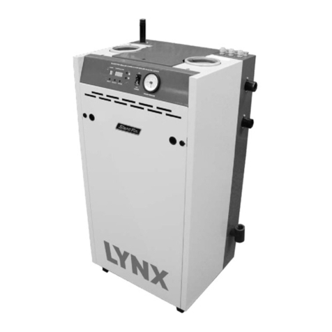
VSPH Series are sealed combustion type boilers, they may be
installed and vented either as direct vent boiler which all air for
combustion is obtained directly from outside or as non-direct
vent boiler which air for combustion is taken from inside the
boiler room.
VSPH boilers must be vented by proper 76 mm (3") diameter.
Stainless Steal venting system (see “vent material” on this
page) through the roof or sidewall.
BOILER ROOM AIR SUPPLY AND VENTILATION
An ample supply of air is required for combustion and ventila-
tion. When buildings are insulated, caulked and weather-
stripped, now or later on, direct openings to outside may be
required and should be provided. If the boiler is not near an
outside wall, air may be ducted to it from outside wall open-
ings.
Provisions for combustion and ventilation air must be made in
accordance with section 5.3, Air for Combustion and Ventila-
tion, of the National Fuel Gas Code, ANSI Z223.1-latest edi-
tion, or CSA B149.1-00 for natural gas and propane or applic-
able provisions of the local building codes. The following rec-
ommendation applies to buildings of energy-saving construc-
tion, fully caulked and weatherstripped.
INSTALLATION IN ENCLOSED BOILER ROOM REQUIRES
TWO UNOBSTRUCTED OPENINGS FOR PASSAGE OF AIR
INTO THE BOILER ROOM:
A. NON-DIRECT VENT INSTALLATION
1. Air drawn horizontally from outdoors DIRECTLY
through an outside wall; one louvered opening near the
floor and one louvered opening near the ceiling, each
opening with a minimum FREE air passage area of 550
mm2per kW (1 square inch per 4000 BTUH) of total
appliances’ input.
2. Air drawn horizontally through HORIZONTAL DUCTS;
one opening near the floor and one opening near the ceil-
ing, each opening with a minimum FREE air passage area
of 1100 mm2per kW (1 square inch per 2000 BTUH) of
total appliances’ input.
3. Air drawn VERTICALLY from outdoors; one opening at
the floor and one opening at the ceiling, each opening
with a minimum FREE air passage area of 550 mm2per
kW (1 square inch per 4000 BTUH) of total appliances’
input.
4. Air drawn from inside the building; one opening near
the floor and one opening near the ceiling, each opening
with a minimum FREE air passage area of 2200 mm2per
kW (1 square inch per 1000 BTUH) of total appliances’
input.
IF BOILERS ARE INSTALLED ADJACENT TO OTHER FUEL
BURNING EQUIPMENT, THE AREA OF FREE OPENINGS
MUST BE APPROPRIATELY INCREASED TO ACCOMMO-
DATE THE ADDITIONAL LOAD.
B. DIRECT VENT INSTALLATION
Adequate air supply should be provided to prevent overheat-
ing of the boiler controls and boiler room. Openings for pas-
sage of air into the boiler room for direct-vent installation must
be at least 1/2of the openings required for the non-direct vent
as mentioned above.
If additional non-direct vent appliances are installed in the
same space and adequate air openings are provided for
them, there are no additional air openings required for the
VSPH boiler.
For both direct and non-direct installation, the following must
be considered:
- Openings must never be reduced or closed. If doors or
windows are used for air supply, they must be locked
open.
- Protect against closure of openings by snow and debris.
Inspect frequently.
- No mechanical draft exhaust or supply fans are to be
used in or near the boiler area.
- Boiler area must never be under negative pressure. The
flow of combustion and ventilating air to the boiler must
not be obstructed.
FLUE GAS VENTING REQUIREMENTS
The Victory VSPH series boiler is a high efficiency, mechani-
cally induced draft boiler and, therefore, requires different
venting arrangements than natural draft, lower efficiency boil-
ers.
THE FOLLOWING INSTRUCTIONS MUST BE CAREFULLY
READ AND FOLLOWED IN ORDER TO AVOID ANY HAZ-
ARDOUS CONDITIONS DUE TO IMPROPER INSTALLATION
OF THE AIR INTAKE AND FLUE GAS VENTING SYSTEM.
The vent piping installation MUST be in accordance with these
instructions and with ANSI Z223.1-latest edition NATIONAL
FUEL GAS CODE, Part 7, Venting of Equipment, or CSA
B149.1-00 for natural gas and propane. Other local codes
may also apply and must be followed. Where there is a con-
flict between these requirements, the more stringent case shall
apply.
The use of a vent damper is NOT permitted on this boiler
series.
VENT MATERIAL
The vent system for direct or non-direct vent installation must
be UL listed single wall 76 mm (3") diameter AL29-4C* stain-
less steel material. The following manufacturers’ systems are
approved for use within a specified minimum and maximum
equivalent vent length for each model. Proper adapter must
be used as a connector between Victory VSPH boilers flue
collar and venting system as shown below:
VICTORY VSPH Models 5
*AL29-4C is a registered Trademark of Allegheny Ludlum Corp
Heat-Fab Part Numbers for various items of vent system are listed in
Slant/Fin Part List.
Heat-Fab. Inc. Saf-T Vent Not required RTV 106 or Dow
Corning 732
Heat-Fab. Inc. Saf-T Vent Not required Not Required
EZ Seal
ProTech System, FasNSeal FSA-SLB-3 Not Required
Inc.
Flex-L StaR-34 SRAFSA3 GE-IS806
International, Inc.
Z-Flex, Inc. Z-Vent O2SVSSLA2 GE, RTV 106
Manufacturer Type/System Adapter Part
No. Sealant

