Slaughter 2205 Operation manual

OPERATION AND SERVICE MANUAL
Model 2205
0 –1.0KV DC / 0.1MΩ–200GΩINSULATION RESISTANCE TESTER
SERIAL NUMBER
Model 2205
©Slaughter Company, Inc., 2002
28105 N. Keith Drive
Lake Forest, Illinois, 60045-4546
U.S.A.
Item 99-10268-01 Ver 1.04 Printed April 29, 2013


Warranty Policy
Slaughter Company, certifies that the instrument listed in this manual meets or exceeds
published manufacturing specifications. This instrument was calibrated using standards
that are traceable to the National Institute of Standards and Technology (NIST).
Your new instrument is warranted to be free from defects in workmanship and material for
a period of (1) year from date of shipment. You must return the “Owners Registration
Card”provided within (15) days from receipt of your instrument.
Slaughter Company recommends that your instrument be calibrated on a twelve-month
cycle. A return material authorization (RMA) must be obtained from Slaughter Company.
Please contact our Customer Support Center at 1-800-504-0055 to obtain an RMA
number. It is important that the instrument is packed in its original container for safe
transport. If the original container in not available please contact our customer support
center for proper instructions on packaging. Damages sustained as a result of improper
packaging will not be honored. Transportation costs for the return of the instrument for
warranty service must be prepaid by the customer. Slaughter Company will assume the
return freight costs when returning the instrument to the customer. The return method
will be at the discretion of Slaughter Company.
Except as provided herein, Slaughter Company makes no warranties to the purchaser of
this instrument and all other warranties, express or implied (including, without limitation,
merchantability or fitness for a particular purpose) are hereby excluded, disclaimed and
waived.
Any non-authorized modifications, tampering or physical damage will void your warranty.
Elimination of any connections in the earth grounding system or bypassing any safety
systems will void this warranty. This warranty does not cover batteries or accessories not
of Slaughter Company manufacture. Parts used must be parts that are recommended by
Slaughter Company as an acceptable specified part. Use of non-authorized parts in the
repair of this instrument will void the warranty.


TABLE OF CONTENTS
INTRODUCTION________________________________________________________2
INSTALLATION AND SAFETY___________________________________________________ 2
SERVICE AND MAINTENANCE__________________________________________________ 10
GLOSSARY OF TERMS _________________________________________________________ 12
SPECIFICATIONS_______________________________________________________14
CONTROLS ____________________________________________________________17
QUICK START__________________________________________________________21
SETUP _________________________________________________________________23
OPERATION ___________________________________________________________26
REMOTE I/O ___________________________________________________________29
CALIBRATION _________________________________________________________31
REPLACEMENT PARTS LIST____________________________________________32
SCHEMATIC INDEX ____________________________________________________33

INTRODUCTION
2
INTRODUCTION
This section is prepared to assist the user of Slaughter manually operated bench type test
equipment with the use, installation, inspection and maintenance of the equipment.
Since any electrical equipment can be hazardous, all procedures described should be
conducted by qualified personnel familiar with safety rules applying to electrical equipment
and who have been thoroughly instructed as to the nature of the procedure, the hazards
involved, and the necessary safety precautions.
Defects and weaknesses in the electrical insulation system must be detected to insure that
the product is safe for use by the consumer. In most windings there are two basic types of
insulation systems. The ground insulation separates the windings from a magnetic core
material or an exposed conductive frame or exterior. The second insulation system is the
wire insulation, which in lower voltage windings is typically a thin film coating of the
wire. These two insulation systems perform different functions in the winding and require
different tests to evaluate their integrity. The Dielectric Withstand Test is used to
evaluate the ground insulation system.
This test has been described by many names; Hi-pot Test, Dielectric Withstand Test,
Insulation Leakage and Breakdown Test, Shorts Check, Ground Check and others. What
ever the name, the purpose is to detect failure of the insulation system that separates the
current carrying portions of an electrical device from any exposed conductive components.
For operator safety reasons, and to avoid possible tester damage,
the product under test SHOULD NOT BE CONNECTED in any
way to the AC power lines.
Typically, it is the responsibility of the manufacturer to establish the proper tests needed
for a particular product to insure they comply with all agency requirements.
INSTALLATION AND SAFETY
For operator safety reasons, and to avoid possible tester
damage, the product under test SHOULD NOT BE
CONNECTED in any way to the AC power lines.
When first received, unpack the equipment carefully and inspect for any hidden damage.
If damage is evident, keep the carton and file a claim with the carrier.
Packed with all Slaughter equipment is a certificate of conformance, operator's manual,
test leads and any required interface connectors.
WARNING
CAUTION

INTRODUCTION
3
To check the unit quickly, install any interface connectors, plug the unit into the proper
voltage and follow the steps outlined under operating instructions. If the unit does not
operate, contact the factory for instructions.
Of prime consideration and importance in the layout and installation of a test station is to
insure the safety both to the operator and any visitors or casual bystanders, invited or
otherwise. As a general rule it is suggested that each test area be in a location with
minimum distractions and not subject to extremes of temperature and moisture.
One of the more important ways to promote safety is through operator training. Benefits
of training are twofold. First, thorough training promotes safety which may significantly
reduce injuries on the job. Second, it ensures adequate testing of the product which helps
increase product reliability. Both of these can have a positive impact on profits.
An additional consideration in any test station is operator comfort. This is affected by the
operator's position, which includes the chair, table, test equipment, the object under test
and the test procedure itself. The chair and work bench or table should be nonconductive
and the table as large as possible to allow sufficient room for the test equipment and the
object under test. Studies should be made of the test requirements and work habits and
steps taken to ensure that any unusual or unnatural motion is not required and to eliminate
any repetitive motions that may produce injuries such as carpel tunnel syndrome.
After the equipment has been installed, a careful study should be made of the test station
to determine what, if any, safeguards are needed. It is suggested that any electrical test
station involving voltages in excess of 42.4 volts peak (approximately 30 volts RMS)
should be equipped with safeguards. These should operate both for the protection of the
operating personnel and for the protection of casual bystanders. At the minimum,
safeguards should prevent the operating personnel or casual bystanders from coming into
contact with the test circuit. In the event electrical interlocks of any sort are required,
either to insure that guards are in place, or to insure that the operator's hands are in a safe
location, the installer should refer to the proper schematic drawing and install these
interlocks in series with the external interlock terminals provided in the tester. All testers
may be safety interlocked with series manual or automatic safety switches, relays, etc. as
desired. In the simpler units, this is done by inserting such interlocks in the AC supply
ahead of the tester. In some units adapter plugs with remote interface controls are
provided for this purpose. We will be happy to provide suggestions and schematics for
safety interlocking our test equipment.
Any electrical power receptacle utilized to operate this equipment must be a properly
grounded three wire receptacle that has been checked for proper polarity.
The test procedure should be well thought out to ensure that it adequately tests the
product to the desired criteria but, that the procedure does not require the operator to
perform tasks that are unsafe. The product should never be touched during a test and in

INTRODUCTION
4
the case of a grounded part the conductive table or conveyor should not be touched
during a test.
Several models of high voltage test equipment are designed with the high voltage output
"floating". There is no ground on either the High side or the Low side of the high voltage
transformer. One of the test leads of the HV transformer is considered the Low side due
to the winding pattern of the transformer, but it is NOT grounded. This arrangement
provides a one type of safety margin to the operator because someone must come in
contact with both leads to receive a shock.
Some models of test equipment have one lead of the output grounded or production
requirements are such that it is impossible or impractical to test a product in an
"ungrounded" configuration. When the tester and the product are grounded, it is
important to remember that the operator is also grounded and need only touch the
ungrounded lead to receive a shock.
A major consideration in testing products that are "grounded" (touching a conductive
conveyor or table) is to insure that the operator or bystanders cannot or will not come in
contact with the table or conveyor during a test. Under some product failure conditions,
the table or conveyor may become "live" and present a high voltage potential to true earth
ground if the table or conveyor is not properly grounded.
It should never be assumed that a conveyor or conductive table is "grounded" just because
it is bolted to the floor. A proper ground is one that has been verified to return to the
input power line ground (earth ground) with a resistance of less than 1/2 ohm. This will
help eliminate "floating" grounds, ground loops and "phantom" voltages between the
object under test and the tester case which is grounded to the power line ground.
The testing of very large items such as recreational vehicles and mobile homes poses
special problems because the safety hazards involved are considerably greater than those
involved in testing smaller objects.
This is because it is possible under fault conditions for the entire outer skin of the object
being tested to become charged to a high voltage. This is particularly bad because these
units are so large that the person conducting the test is in no position to observe whether
or not any other people are in a potentially dangerous position during the test.
If proper precautions are taken, there will be no hazard, but even so, it is highly desirable
that care be taken to isolate the test object when a test is being conducted. Suggested
methods of doing this are the use of rope barriers, warning signs, and fully enclosed test
areas.
Before conducting a test on these units, care should be taken to see that the frame and
skin of the unit are connected to a solid ground, and also that the ground conductor of the
electrical system is connected to a solid ground. This will eliminate most test hazards, but

INTRODUCTION
5
bear in mind it is possible for some sections of the skin to have poor electrical connection
and that they thereby, can become a potential safety hazard in the event of a fault. This is
why isolation of the vehicle during the test is recommended.
Once these safety precautions have been taken and it has been established that the frame
and skin are properly grounded, the operator can proceed with the dielectric test.
Good safety practice dictates labeling of hazards properly. Since high voltage testing can
be hazardous, the work station should be labeled. Naturally, the location of the label
should be carefully selected so that it can be placed in a location that will do the most
good.
In some cases, this may be on the test instrument itself, and in others, it may be in a
location directly in front of the operator, somewhat removed from the instrument.
In addition to instrument labeling, we are supplying labels that you should apply in
accordance with the above suggestions. If you need a couple more, please let us know...
we will gladly supply them. If you need a large quantity, these are available at a nominal
price.
A final word about high voltage testers: Generally, commercial high voltage test
equipment is not in itself hazardous. The hazards come about when the equipment is
improperly used. These testers, when used properly and in a safe manner, can be a check
on the quality and reliability of your product. If used incorrectly and without proper
consideration for safety, they represent a hazard for both operating personnel and casual
bystanders. We strongly recommend proper training for all personnel involved in testing.
High Voltage Testing
High Voltage Testing has historically been the most misunderstood, misapplied,
misinterpreted inspection function in the average factory. Some manufacturers have
looked upon the High Voltage Dielectric Withstand test or Hipot test as it is more
commonly known, as an extra operation that must be performed to satisfy some agency
requirement. Though many times the high voltage test is simply a safety measure, its value
in quality control should not be overlooked.
First and foremost, the hipot test is done to ensure the safety of customers by detecting
"grounded" or "shorted" products. By applying a high voltage between "live" current
carrying parts of the product and the framework which is normally supposed to be "dead,"
or well insulated from the "live" parts, the product is "proof tested" against grounds or
shorts which at the least might cause inconvenience and at the most can cause fire or
injury. During the hipot test, all insulation is abnormally stressed for the duration of the
test. Additionally, it is possible to detect "potential" shorts. Consider there is a bare
conductor about .015" from the frame. In the factory, the product is clean and new, but
after a year or two of service, contaminants, dust, and moisture may cause this gap to
bridge at line voltage resulting in a shock hazard to the consumer.

INTRODUCTION
6
Secondly, hipot testing is done as a quality control measure. Incipient failures in the
insulation of any portion of the product, whether due to workmanship, components or
materials are detected by the hipot test before the product is shipped out to cause
inconvenience, dissatisfaction and expense in the field.
The most often asked questions are, "Is hipot testing destructive?" and "Should I use AC
or DC for the hipot test?"
Today's modern, commercially available high voltage production line testing equipment is
generally not destructive. For most consumer product testing, testers have sufficient
sensitivity and response time that short circuit currents can be held to non-destructive
levels.
The question of AC or DC is best answered by the question, "What do the specs say?"
For the production hipot test, agency requirements almost invariably specify an AC test.
Generally, AC hipot testing is considered by many to be more stressful to the insulation
than DC hipot testing because of the periodic polarity reversal. Some believe AC testing
tends to accelerate breakdown due to material flaws. During use, products are more likely
to experience AC voltage transients than to experience DC voltage transients. Therefore,
AC hipot tests provide more realistic conditions than DC hipot tests.
The next most common question about hipot testing is, "How much voltage should I use?"
Again, "What do the specs say?" As a rule-of-thumb, many applications will require 1000
volts plus twice the normal operating voltage for one minute. Increasing the test voltage
by 20% usually allows the test time to be reduced to one second. Automotive products
will generally specify 500 volts.
Armatures are produced in both a "single insulated" and a "double insulated"
configuration. With single insulated armatures, the commutator and windings are
insulated from the iron stack and the shaft which, electrically speaking, are common.
Double insulated armatures additionally have the iron stack insulated from the shaft. This
provides "double insulation" between the current carrying components, the commutator
and the windings, and any exposed dead metal components, normally the shaft.
On single insulated armatures, the dielectric withstand test voltage is normally applied
between the commutator and the shaft.
Double insulated armatures, however, will normally have a dielectric withstand voltage
applied between the commutator and the iron stack and another dielectric withstand
voltage between the iron stack and the shaft. If these two voltages are applied
simultaneously and the voltage sources are properly phased, a consequential voltage equal
to their sum will be applied between the commutator and the shaft.
INTRODUCTION
7
A hipot test attempts to detect or measure phenomena that indicate electrical problems
such as leakage, breakdown and arcing.
Leakage is a flow of current. Leakage becomes significant under two conditions. Any
increase in resistive leakage is a "red flag" indication that quality in insulating materials
used in the device has in some manner deteriorated. Total leakage becomes significant if it
reaches such a level that it becomes perceptible to the user of the equipment. UL
extensively researched the area of perception threshold and electrical shock. They found
that, generally, "women are more sensitive to leakage current than men and a current flow
of 0.5 milliamperes or less at 60 hertz does not produce a reaction which is considered to
be hazardous to the individual or to those nearby."
Some leakage exists in any product, though, in many cases, it will be so minute to defy
measurement. It exists for two reasons; first leakage current exists simply because no
insulating materials are perfect and have infinite resistance. This is generally referred to as
resistive leakage and can be calculated from Ohms Law, E=IR where E is the applied
voltage, I is current flow in amperes and R is the resistance in ohms. Second, any
electrical device, by virtue of the fact that it is made of conductive material with electrical
circuits in close proximity, exhibits what can be called an "inherent capacity effect." This
is actually a capacity and, if we apply AC voltage, current will flow. This is generally
referred to as capacitive leakage. The equivalent resistive value of the capacitance (Xc)
may be calculated from the formula, Xc=1/(2πfC) where Xc is the equivalent resistance in
ohms, f is frequency of the applied voltage in hertz and C is the capacitance in farads. The
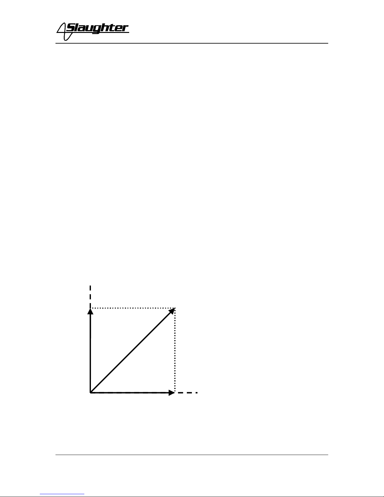
combination of these two components of leakage (figure 1.) is referred to as the total or
complex leakage.
Current Vector
figure 1.
I(r)
I(c)
I(t) I(c) = CAPACITIVE CURRENT
I(r) = RESISTIVE CURRENT
I (t) = TOTAL CURRENT
INTRODUCTION
8
The capacitive leakage is an inherent characteristic of the device controlled primarily by
design details. The resistive leakage is a characteristic of insulating materials used and the
amount of resistive leakage is generally an indication of the quality of the insulation. This
is particularly true when identical devices are being comparatively tested. Both capacitive
and resistive leakages vary, almost linearly, with the applied test voltage.
In the average electrical device during AC hipot tests, the resistive current flow is
normally much smaller than the capacitive current flow, so changes in the resistive current
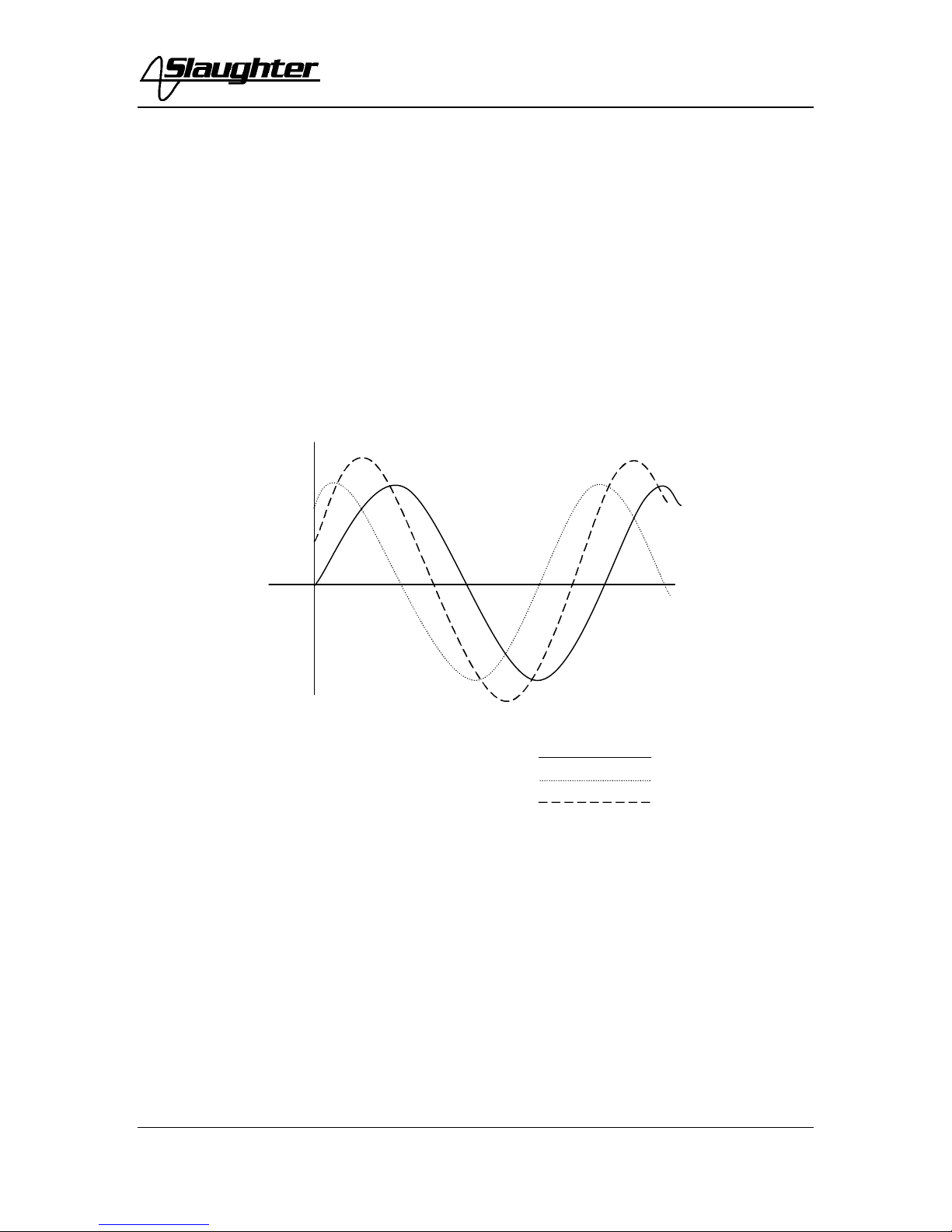
do not have a significant effect on the total current. The capacitive current, however, is
out of phase with the resistive current and can be cancelled in the measurement (figure 2.).
With this type of test arrangement, the masking effect of the capacitive current is greatly
reduced or eliminated and small variations in insulation resistance become detectable.
RESISTIVE CURRENT
CAPACITIVE CURRENT
TOTAL CURRENT
figure 2.
Breakdown is also a flow of current. However the term is usually used to denote an
actual insulation failure. It is readily distinguishable from leakage because the current does
not vary linearly with the applied voltage, but instead rises suddenly when the critical or
breakdown voltage is reached. Often, but not always, arcing is associated with
breakdown.
Arcing occurs in solids and liquids as well as gases. Arcing typically involves currents on
the order of 0.4 amperes or more and indicates a potentially dangerous breakdown of
insulation or abnormal current flows inside a device.

INTRODUCTION
9
The ability of high voltage test equipment to react to the excessive current flow or failure
of the product under test is often referred to as "sensitivity."
For many years, users of high potential (hipot) dielectric testers tolerated considerable
sensitivity differences between individual testers. Products rejected by one tester might be
accepted by another. If the two testers were distinctly different models or were made by
different manufactures, the question of which tester to rely upon was a difficult one.
Unfortunately, the tester chosen was sometimes the one that would accept the products.
In a majority of these situations, the real problem was a lack of an acceptable standard for
tester sensitivity. Many low cost production line testers in the past were essentially
designed as "go/no-go" testers and sensitivity was often whatever was convenient for the
manufacturer.
The variance of the sensitivity curves between different manufacturers and different
models was a major factor in U.L.'s (Underwriters Laboratories) move to try and
standardize production line hipot test equipment sensitivity. These tester performance
requirements have come to be commonly known as the "120 K requirement."
Unless the hipot tester was designed to meet the "120 K" specifications, it is unlikely that
it will meet all of the requirements. The tester's suitability must be verified.
In general, the original U.L. "120 K" specifications require the tester to reject within .5
seconds when connected to an impedance of 120,000 (120 K) ohms at the specified
testing voltage. Additionally, the output voltage sign wave tolerance is specified and the
output voltage regulation is required to be -0%, +20%.
Various agencies other than U.L. have their own versions of the "120 K" type
specifications. As with all testing specifications, the manufacturer must ensure that they
are in compliance with the latest testing requirements for their particular product.
The Insulation Resistance Test
Some dielectric analyzers today come with a built in insulation resistance tester. Typically,
the IR function provides test voltages from 500 to 1,000 volts DC and resistance ranges
from kilohms to gigaohms. This function allows manufacturers to comply with special
compliance regulations. BABT, TÜV, and VDE are agencies that may under certain
conditions require an IR test on the product before a Hipot test is performed. This
typically is not a production line test but a performance design test.
The insulation resistance test is very similar to the hipot test. Instead of the go/no go
indication that you get with a hipot test the IR test gives you an insulation value usually in
Megohms. Typically the higher the insulation resistance value the better the condition of
the insulation. The connections to perform the IR test are the same as the hipot test. The
measured value represents the equivalent resistance of all the insulation which exists
between the two points and any component resistance which might also be connected
between the two points.

INTRODUCTION
10
Although the IR test can be a predictor of insulation condition, it does not replace the
need to perform a Dielectric Withstand test.
TYPES OF FAILURES DETECTABLE ONLY WITH A HIPOT TEST
•Weak Insulating Materials
•Pinholes in Insulation
•Inadequate Spacing of Components
•Pinched Insulation
SERVICE AND MAINTENANCE
User Service
To prevent electric shock do not remove the instrument cover. There are no user
serviceable parts inside. Routine maintenance or cleaning of internal parts is not
necessary. Any external cleaning should be done with a clean dry or slightly damp cloth.
Avoid the use of cleaning agents or chemicals to prevent any foreign liquid from entering
the cabinet through ventilation holes or damaging controls and switches, also some
chemicals may damage plastic parts or lettering. Schematics, when provided, are for
reference only. Any replacement cables and high voltage components should be acquired
directly from Slaughter Company. Refer servicing to a Slaughter Company authorized
service center.
SLAUGHTER COMPANY, INC.
28105 N. KEITH DRIVE
LAKE FOREST, IL 60045-4546 U.S.A.
(PHONE: 1 (847) 932-3662
1 (800) 504-0055
FAX: 1 (847) 932-3665
E-MAIL : support@hipot.com
www.hipot.com
Service Interval
The instrument and its power cord, test leads, and accessories must be returned at least
once a year to a Slaughter Company authorized service center for calibration and
inspection of safety related components. Slaughter Company will not be held liable for
injuries suffered if the instrument is not returned for its annual safety check and maintained
properly.
User Modifications
Unauthorized user modifications will void your warranty. Slaughter Company will not be
responsible for any injuries sustained due to unauthorized equipment modifications or use
of parts not specified by Slaughter Company. Instruments returned to Slaughter Company
with unsafe modifications will be returned to their original operating condition at your
expense.

INTRODUCTION
11
Packaging
Original Packaging: Please retain all original packaging materials if you do not have an
alternate method of repackaging. If you are returning your instrument to us for servicing
please repackage the instrument in its original container or use an alternate packaging
solution. Please do not reuse the original packing material if there appears to be damage
or missing packing material. Contact our customer support department (1-800-504-0055)
for an RMA (return materials authorization) number. Please enclose the instrument with
all options, accessories, and test leads. Indicate the nature of the problem or type of
service needed. Also, please mark the container "FRAGILE" to insure proper handling.
Other Packaging: If you do not have the original packaging materials please follow these
guidelines:
1). Wrap the instrument in a bubble pack or similar foam. Enclose the same information
as above.
2). Use a strong double-wall container that is made for shipping instrumentation. 350 lb.
test material is adequate.
3). Use a layer of shock-absorbing material 70 to 100 mm (3 to 4 inch) thick around all
sides of the instrument. Protect the control panelwith cardboard.
4). Seal the container securely.
5). Mark the container "FRAGILE" to insure proper handling.
6). Please ship model 2205 via Federal Express or UPS air.
7). Please refer in all correspondence to your RMA number.

INTRODUCTION
12
GLOSSARY OF TERMS
ACCURACY is the condition or quality of conforming exactly to a standard. The
accuracy of an instrument is the extent to which the average of many measurements made
by the instrument agrees with the true value or standard being measured. The difference
between the average and the true value is the error. When this condition is a result of the
measuring instrument, it is known as out of calibration. An instruments measuring
accuracy must be considered over the whole range of the measuring instrument. This is
often expressed as linearity.
AVERAGE VOLTAGE is the sum of the instantaneous voltages in a half cycle wave
shape divided by the number of instantaneous voltages. In a sine wave, the average
voltage is equal to .637 times the peak voltage.
EMF (electromotive force) is the energy per unit charge supplied by a source of electricity
(normally expressed in volts).
The FULL SCALE VALUE is equal to the largest value of the actuating electrical
quantity which can be indicated on the scale or, in the case of instruments having their
zero between the ends of the scale; the full scale value is the arithmetic sum of the values
of the two ends of the scale.
IMPEDANCE is the apparent resistance, expressed in ohms, offered by an alternating
current circuit to the passage of electrical energy. Since frequency is one of the factors
affecting impedance, the frequency of applied energy must be specified.
INDUCTANCE is the property of an electric circuit by which a varying current induces
an emf in that circuit or a neighboring circuit.
L = a²n²/(9a + 10b)
a = coil radius in inches
b = coil length in inches
n = number of turns
LOADED TEST(ing) VOLTAGE is the actual testing voltage developed across the load
(product under test). This voltage will be lower than the open circuit voltage because of
the internal impedance of the H.V. transformer and any series limit resistance of the tester.
OPEN CIRCUIT VOLTAGE is the output voltage of the tester prior to the connection
of a load (product under test).
PEAK VOLTAGE is the maximum value present in a varying or alternating voltage.
This value may be either positive or negative. The peak value is equal to 1.414 (√2) times
the R.M.S. value.

INTRODUCTION
13
PRECISION or REPEATABILITY is the variation in readings obtained when repeating
exactly the same measurement. The precision of an instrument is the ability to repeat a
series of measurements on the same piece and obtain the same results for each measured
value. The variation in the measured values can be expressed in terms of a standard
deviation of the measuring error. The instrument will be more precise if the standard
deviation is smaller.
Accuracy versus Precision: Confusion often exists between the terms accuracy and
precision because the terms are often interchanged in their usage, but they are two
different concepts. The accuracy of an instrument can be improved by recalibrating to
reduce its error, but recalibrating generally does not improve an instrument’s precision.
R.M.S. (ROOT MEAN SQUARE) is the square root of the mean of the instantaneous
values squared.
R.M.S. VOLTAGE is the effective value of a varying or alternating voltage. The
effective value is that value which would produce the same power loss as if a continuous
voltage were applied to a pure resistance. In sine wave voltages, the R.M.S. voltage is
equal to .707 times the peak voltage.
SENSITIVITY is the impedance through which a tester will detect a fault. Sensitivity is
usually expressed in Ohms. One of the most common examples is the UL 120K ohm
minimum sensitivity requirement.
VOLT AMPERE (VA) is the product of the R.M.S. voltage applied to a circuit and the
R.M.S. current, in amperes, flowing through it.

SPECIFICATIONS
14
SPECIFICATIONS
KEY FEATURES & BENEFITS OF MODEL 2205
1. Pass/fail operation
A programmable limit can be set for pass/fail operation, eliminating operator
judgments. An audio alarm and reject lamp notify the operator of failures.
2. No load setup of trip current and output voltage.
Operators can set output voltage and resistance limits to the desired levels in the
absence of high voltage.
3. Automatic storage of test program.
The instruments will power up with the parameters that were used during the last test
to avoid operator set-up errors.
4. All parameters for the setups can be adjusted through a simple menu driven program.
The easy to follow setup screens ensure that the operator correctly sets up all test
parameters.
5. Line and load regulation.
Tests are more repeatable and reliable, since proper voltage is consistently applied to
all devices being tested, regardless of fluctuations in the line input voltage or the
load created by the device under test.
6. PLC Remote Control.
Inputs and outputs for PLC control are available through a 9-pin D type connector
on the back panel.
7. LED display with meter memory.
Easy-to-read digital display simplifies the task of setting test parameters and
interpreting test results, which reduces errors and makes the operator’s job easier.
Meter memory allows operators to review the last test results.
8. Flashing high voltage indicator.
A flashing LED located to the right of the display clearly indicates when high voltage
is active to provide maximum operator safety.
9. Tamper-resistant front panel design.
Prevents operators from inadvertently or accidentally modifying test parameters and
ensures consistent and reliable test results, minimizing the need for costly and time
consuming product re-testing.

SPECIFICATIONS
15
Model 2205 Functional Specifications
Insulation Resistance Tester
INPUT
Voltage 115 / 230 V selectable, ±15% variation
Frequency 50 / 60 Hz ±5%
Fuse 1 Amp 250VAC fast acting
INSULATION RESISTANCE TEST
Output Voltage Range:
Resolution:
Accuracy:
Ripple:
30 –1000VDC
1 Volt
±(1% of Setting + 1V) (relative to displayed
output)
< 2%
Voltage Display Low Range:
High Range:
Resolution:
Accuracy:
0.0V –100.0VDC
101V –1000VDC
0.1V (Low Range), 1V (High Range)
±(2% of reading +2V)
Resistance Display Range:
Accuracy:
0.01MΩ–200.0GΩ(4 Digit, Auto Ranging)
30 –499V
0.1MΩ–1GΩ
±(3% of reading + 2 counts)
1 –20GΩ
±(5% of reading + 2 counts)
500 –1000V
0.1MΩ–1GΩ
±(2% of reading + 2 counts)
1 –20GΩ
±(3% of reading + 2 counts)
20 –200GΩ
±(10% of reading + 2 counts)
Timer Display Range:
Resolution:
Accuracy:
0.0 –999.9 seconds
0.1 second
±(0.1% of reading + 0.05 seconds)

SPECIFICATIONS
16
INSULATION RESISTANCE TEST
Failure Settings Low Limit: 0.1MΩ–999.9MΩ
1000MΩ–9999MΩ
10.0GΩ–200.0GΩ
Dwell Time Setting 1.0 –999.9 seconds, 0.1 second / step
“0”for continuous running
Delay Time Setting 0.1 –999.9 seconds, 0.1 second / step
Discharge Automatic Discharge of Device Under Test
Indicator: Green < 30 V, Red > 30 V
GENERAL
Remote Interface Provided through 9 pin D type connector
1. Inputs: test , reset, safety interlock
2. Outputs: pass, fail and test in progress
Line Cord Detachable 6 ft. (1.8m) power cable terminated in a three prong
grounding plug.
Terminations High Voltage Output –Alden Socket
Shielded Return –BNC Connector
Mechanical Dimensions: (W x H x D): (120mm x 133mm x 300mm)
Environmental Operating Temperature:
Relative Humidity: 32° − 104°F (0° − 40°C)
0 –80%
Calibration Traceable to National Institute of Standards and Technology
(NIST). Calibration controlled by software. Adjustments are
made through front panel keypad in a calibration mode activated
by rear panel switch. Calibration information stored in non-
volatile memory.
Table of contents
Other Slaughter Test Equipment manuals


Popular Test Equipment manuals by other brands


National Refrigeration Products
National Refrigeration Products LV5 operating instructions

Glas-Col
Glas-Col 099D HST230N User instructions

Laversab
Laversab 6500 user manual

Keysight
Keysight Infiniium 90000A Series Service guide

EXFO
EXFO ConnectorMax MFS-12 Quick reference guide

Ametek
Ametek Crystal HPC51 Operation manual


