manuals.online logo
Brands
  1. Home
  2. •
  3. Brands
  4. •
  5. EXFO
  6. •
  7. Test Equipment
  8. •
  9. EXFO ConnectorMax MFS-12 User manual

EXFO ConnectorMax MFS-12 User manual


14 To perform the three captures, the movable part of the inspection tip is moved with the trigger. A
capture is made for each position.
Inspection tip (movable part)
Indicates the position to follow to
perform the 3 captures.
Trigger
The icons on screen indicate when you can change the position of the inspection tip and the status
LED as well. When the LED is blue and stops flashing, you can perform a capture.
14a Using the trigger, slide the movable part of the inspection tip to perform each capture.
14b Once you are satisfied with the inspection, tap .
OR
Press the Fiber Inspection Probe capture control button.
15 When the last capture is performed, the analysis starts immediately.
The polarity of a multifiber patchcord refers to how the fibers are linked between the transmitting (Tx) and
receiving (Rx) connectors. The application refers to the TIA 568 standard which defines three polarity types: A,
B, and C. Any other fiber mappings in a multifiber patchcord will result in an unknown polarity type.
Analyzing Polarity Results
The results are available as an image or in
a detailed table.
A fail status either on the inspection of the
connector, the polarity, or continuity will
result in a global fail status.
Discontinuity icon
Analyzing Inspection Results
The image overlay indicates the inspection
status of the connector per zone.
Following the analysis, an image of the identified elements and defects is overlayed on the connector image.
The color of the circles indicates the inspection status of the connector per zone. Red refers to a fail status
whereas green to a pass.
Analyzing Continuity Results
The continuity in a fiber refers to the ability for each fiber of a multifiber patchcord to conduct the light from one
end to the other. With the Fiber Inspection Probe at the receiving end, it is possible to determine on which fibers
discontinuities are found ( ).
Discontinuities
found on fibers
are displayed in
red.
MFS-12/MFS-24
ConnectorMax MPO Test Solution (iOS)
The Multifiber Source (MFS) produces a light pattern that, once injected into a fiber, is detectable by the EXFO’s
Fiber Inspection Probe equipped with an MPO tip (12 or 24 fibers). With the MFS, the probe will test the
continuity and polarity of the link under test in addition to performing the connector inspection.
Only the probes identified as MF-Ready allow you to use the MFS or the MPO tip.
Installing the FIP Nozzle
You need to install the removable nozzle and the inspection tip on the probe before you start working. The
nozzle is interchangeable and you can insert it key up or key down. To facilitate the installation process, install
the removable nozzle on the inspection tip first.
1Install the removable nozzle (key up or key down) on the metal rod of the inspection tip and align the
key of the nozzle with the notch of the inspection tip until you feel it click in place.
Inspection tip
Removable nozzle
MF-Ready probe
Retaining nut
2
Tighten the retaining
nut clockwise.
To change the nozzle,
untighten,
counterclockwise.
Quick Reference Guide
© 2018 EXFO Inc. All rights reserved.
Printed in Canada (2018-11)
P/N: 1074619 Version: 1.0.0.1 For more information,
refer to the user guide.
3Install the inspection tip on the MF-Ready probe by aligning the key of the probe with the notch of the
inspection tip.
Inspection tip (movable part)
MF-Ready probe
Trigger 4Tighten the retaining nut clockwise.
Note: If you cannot see the notch of the inspection tip, slide the movable part of the inspection tip with the
trigger towards the nozzle.
Setting up the Multifiber Source Inspecting Multiple Fiber Ends
When you connect an MF-Ready probe to your smart device, you can view and inspect multiple fiber ends right
away. This type of inspection requires three captures. As soon as the third capture is performed, the analysis
process starts. If you only want to inspect a connector without testing polarity and continuity, ensure that the
MFS is turned off before proceeding. Otherwise, the light emitted by the MFS could be mistaken for dirt which
would result in an erroneous fail status.
6
8
In Live Video mode, tap the Test Configuration
row.
The MFS allows you to test continuity and polarity (based on A, B, or C polarity types) on multifiber links
terminated with MPO connectors. Its design includes a cable management system that allows you to use a
patchcord as connector savers for the MPO connectors on the source.
1Connect the APC connector of the
patchcord to the adapter.
On/Off button with power LED
Battery level indicator
3
If you are using a
patchcord having a
single connector, you
can connect it to any of
the two adapters. With
an MPO-24 split (Y)
patchcord, you must
connect each of its ends
to one of the adapters.
4Open the dust cap and connect the DUT to the appropriate adapter according to the
connections you made in the previous step. If you have connected an MPO-24 split
patchcord, you will have to connect the DUT, in turn, to each of the two adapters.
5Connect the other end of the DUT
to the removable nozzle of the
probe.
2
Secure the
patchcord in
place by
wrapping it
around the unit.
11 Select Multiple Fiber Connector,
and then set the other parameters
according to your needs.
Key orientation of the connector (key up
or key down, depending on the position
of the nozzle)
Fiber configuration of the connector you
use
To validate the
cleanliness of the fibers
of the connector
To stop the analysis as soon as a fail status is detected
on a fiber
Type of expected polarity for your tests
Tap the arrow.
10
Select a test configuration to use for your test.
12
13 If the connector is dirty, remove it from the probe, clean it and reinspect it.
Note: If you are working with an FIP-435B, you can
activate the auto focus feature using the down
arrow in live video mode.
1Turn on the probe.
2Ensure the Wi-Fi is activated on your smart device.
3Go to the device Settings and select Wi-Fi.
4Select the wireless probe you want to work with.
5Start the ConnectorMax2 Mobile application.
Tap Start Live Video.
7Insert the connector into the removable nozzle you have already installed.
Tap the Measurement Name row to configure
the automatic file naming.
9

This manual suits for next models

1

Other EXFO Test Equipment manuals

EXFO IQS-2150 User manual

EXFO

EXFO IQS-2150 User manual

EXFO IQS-2600B User manual

EXFO

EXFO IQS-2600B User manual

EXFO CT440 Series User manual

EXFO

EXFO CT440 Series User manual

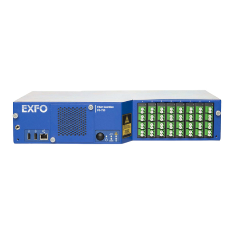
EXFO Fiber Guardian FG-750 User manual

EXFO

EXFO Fiber Guardian FG-750 User manual

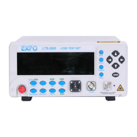
EXFO LTS-3900 User manual

EXFO

EXFO LTS-3900 User manual

EXFO IQ-2600B User manual

EXFO

EXFO IQ-2600B User manual

EXFO FTB-700 Series User manual

EXFO

EXFO FTB-700 Series User manual

EXFO AXS-200/635 User manual

EXFO

EXFO AXS-200/635 User manual

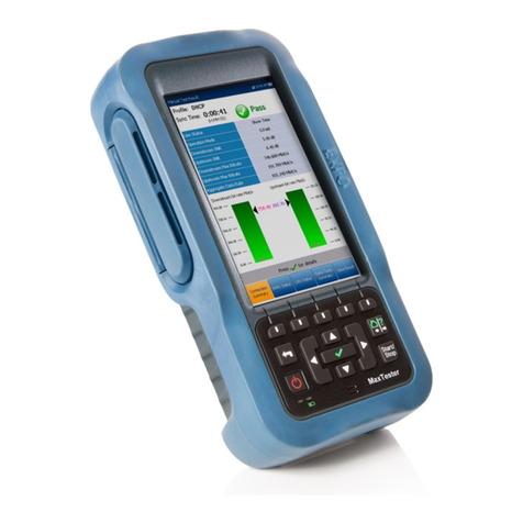
EXFO MaxTester 630G User manual

EXFO

EXFO MaxTester 630G User manual

EXFO LETP-700 Series User manual

EXFO

EXFO LETP-700 Series User manual

EXFO RTU-310 User manual

EXFO

EXFO RTU-310 User manual

EXFO AXS-200/610 User manual

EXFO

EXFO AXS-200/610 User manual

EXFO FTB-2 User manual

EXFO

EXFO FTB-2 User manual

EXFO bv10 User manual

EXFO

EXFO bv10 User manual

EXFO OTH-7000 User manual

EXFO

EXFO OTH-7000 User manual

EXFO Fiber Guardian FG-750 User manual

EXFO

EXFO Fiber Guardian FG-750 User manual

EXFO EXFO MaxTester DSL User manual

EXFO

EXFO EXFO MaxTester DSL User manual

EXFO Power Blazer User manual

EXFO

EXFO Power Blazer User manual

EXFO BRT-320 User manual

EXFO

EXFO BRT-320 User manual

EXFO FTB-610 User manual

EXFO

EXFO FTB-610 User manual

EXFO CableSHARK P3 User manual

EXFO

EXFO CableSHARK P3 User manual

EXFO FTB-700 Series User manual

EXFO

EXFO FTB-700 Series User manual

EXFO EX Series User manual

EXFO

EXFO EX Series User manual

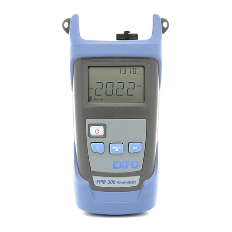
EXFO FPM-300 User manual

EXFO

EXFO FPM-300 User manual

Popular Test Equipment manuals by other brands

Elcometer 506 user guide

Elcometer

Elcometer 506 user guide

Tektronix 221 instruction manual

Tektronix

Tektronix 221 instruction manual

Hioki BT3564 instruction manual

Hioki

Hioki BT3564 instruction manual

Tenma 72-17175 manual

Tenma

Tenma 72-17175 manual

VOLTCRAFT DSO-5072H user manual

VOLTCRAFT

VOLTCRAFT DSO-5072H user manual

Bayrol Pooltester pH-O2 instruction manual

Bayrol

Bayrol Pooltester pH-O2 instruction manual

Technosmart TS-CE-WIFIEND1 user manual

Technosmart

Technosmart TS-CE-WIFIEND1 user manual

Aquasol Digital AM-DO-01 user guide

Aquasol Digital

Aquasol Digital AM-DO-01 user guide

Anritsu Site Master S113B user guide

Anritsu

Anritsu Site Master S113B user guide

Conrad 857334 operating instructions

Conrad

Conrad 857334 operating instructions

Get Control E84 user manual

Get Control

Get Control E84 user manual

Imada ESL-200C instruction manual

Imada

Imada ESL-200C instruction manual

Alcolizer HH4 user manual

Alcolizer

Alcolizer HH4 user manual

Iwatsu SS-7847A Operation manual

Iwatsu

Iwatsu SS-7847A Operation manual

VOLTCRAFT DSO-1062D Brief instructions

VOLTCRAFT

VOLTCRAFT DSO-1062D Brief instructions

VIAVI Solutions T-BERD Quick Card User Guide

VIAVI Solutions

VIAVI Solutions T-BERD Quick Card User Guide

TSI Instruments Qfit user manual

TSI Instruments

TSI Instruments Qfit user manual

SIGLENT TECHNOLOGIES SDS1202X-E user manual

SIGLENT TECHNOLOGIES

SIGLENT TECHNOLOGIES SDS1202X-E user manual

manuals.online logo
manuals.online logoBrands
  • About & Mission
  • Contact us
  • Privacy Policy
  • Terms and Conditions

Copyright 2025 Manuals.Online. All Rights Reserved.