SLE 2000 HFO User manual

Issue
10
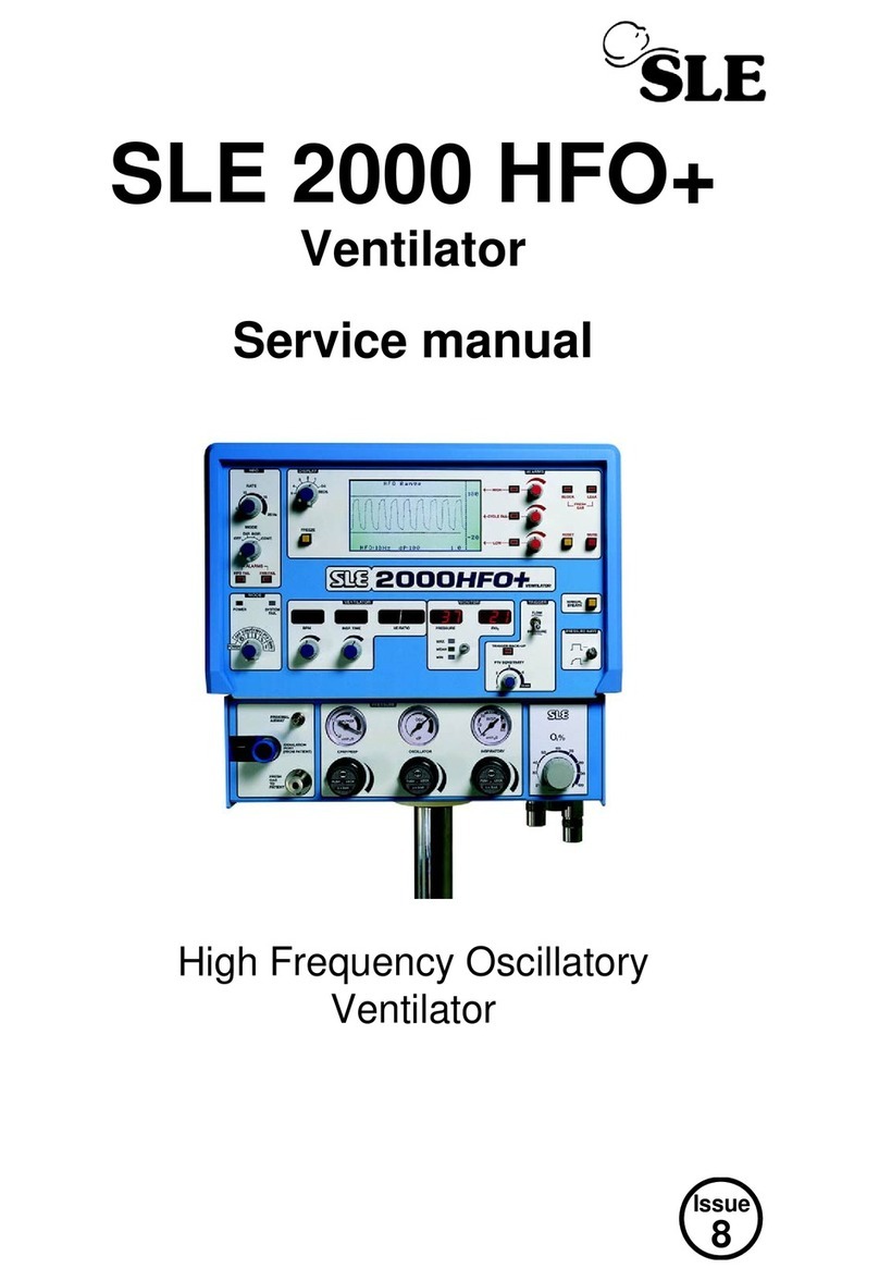
SLE 2000 HFO
Ventilator
Service manual
High Frequency Oscillatory
Ventilator
0120

Page 2 of 258 Issue 10 (01/10/2004)
Contact Information:
All rights reserved. No part of this publication may be reproduced, stored in any retrieval system, or transmitted in
any form or by any means, electronic, mechanical, photocopy, recording or otherwise, without prior permission of
SLE. © Copyright SLE 01/10/2004.
Manual : SM0006 Issue 10
SLE Part Nº: N2005/00
SLE Limited
Twin Bridges Business Park
232 Selsdon Road
South Croydon
Surrey CR2 6PL
Telephone: +44 (0)20 8681 1414
Fax: +44 (0)20 8649 8570
Web site: www.sle.co.uk

Issue 10 (01/10/2004) Page 3 of 258
Contents
1. Introduction ................................................................................................................. 10
2. Ventilator Control Description ................................................................................... 12
2.1. Front Panel......................................................................................................... 13
2.1.1. Front panel controls..................................................................................... 13
2.2. Back Panel ......................................................................................................... 15
2.3. Electronic Module............................................................................................... 16
3. Access to the SLE2000 HFO ...................................................................................... 18
3.1. Electronic Module............................................................................................... 18
3.2. Pneumatic Module.............................................................................................. 19
3.3. Separating the two modules............................................................................... 20
3.4. Removal of the oxygen cell ................................................................................ 21
3.4.1. Screw in method.......................................................................................... 21
3.4.2. Trapped Method........................................................................................... 21
3.5. Removal of the motor assembly........................................................................ 22
3.5.1. Motor assemblies......................................................................................... 22
3.5.2. Removal of N2524 motor assembly............................................................. 22
3.5.3. Removal of N2524/01 or N2524/02 motor assembly................................... 24
4. Cleaning, Disinfection and Sterilization ................................................................... 28
4.1. Preparation of a new ventilator........................................................................... 28
4.2. Cleaning and disinfection of an in-service ventilator .......................................... 28
4.2.1. Cleaning, Disinfection & Sterilization chart.................................................. 29
4.3. Cleaning method ................................................................................................ 29
4.4. Disinfection method............................................................................................ 30
4.5. Sterilization method............................................................................................ 30
5. Filter Systems ............................................................................................................. 31
5.1. Bacterial filter, SLE Part Nº:N2029 (Autoclavable)............................................. 31
5.2. Bacterial filter, SLE Part Nº:N2587 (Single use)................................................. 31
5.2.1. Precautions when using bacterial filter N2587............................................. 31
6. Maintenance ................................................................................................................ 32
6.1. Monthly Operational Checks .............................................................................. 32
6.1.1. Battery condition and LED display test........................................................ 32
6.1.2. Air and Oxygen Supply Failure Alarm test................................................... 32
6.1.3. Condition of O2Cell..................................................................................... 32
6.1.4. Inspiratory Nozzle........................................................................................ 33
6.1.5. CPAP pressure check.................................................................................. 33
6.1.6. HFO pressure check.................................................................................... 33
6.2. Servicing............................................................................................................. 34
7. Overhaul ...................................................................................................................... 36
8. Exchanging a Pneumatic Unit ................................................................................... 38

Page 4 of 258 Issue 10 (01/10/2004)
9. SLE 2000 HFO Set up and Calibration ......................................................................40
9.1. Recommended Equipment.................................................................................40
10. Step 1: Pneumatic Module Initial Setup ..................................................................40
10.1. Internal Pressure Regulator..............................................................................40
10.2. O2Cell Flow Needle Valve ...............................................................................40
10.3. Fresh Gas Flow Needle Valve..........................................................................40
11. Step 2: Electronic Module Setup .............................................................................41
11.1. Power Supply Unit............................................................................................41
11.1.1. Voltage verification and setting ..................................................................41
11.2. Ventilator CPU Board (A0702/04)....................................................................42
11.2.1. System Watchdog......................................................................................42
11.2.2. U18/26(ADC)..............................................................................................42
11.2.3. Buffered transducer output.........................................................................42
11.2.4. Fresh Gas Block and Leak Alarm ..............................................................43
11.2.5. Patient Purge Pressure Display Compensation.........................................43
11.2.6. Maximum Inspiration Time.........................................................................44
11.2.7. Airway Trigger Calibration..........................................................................44
11.2.8. PTV sensitivity control................................................................................44
11.3. Motor Drive Board (A0739/02)..........................................................................45
11.4. HFO Main Board (A0736/03)............................................................................45
11.4.1. Scaling of pressure LCD display................................................................45
11.4.2. Bargraph Calibration..................................................................................46
11.4.3. One second timer.......................................................................................46
11.4.4. Motor Stall Alarm........................................................................................46
11.4.5. Fan Fail Alarm Verification.........................................................................46
11.4.6. HFO Rate Display......................................................................................47
11.4.7. HFO Alarm.................................................................................................47
11.5. Alarm module and oxygen conditioning circuit (A0738/02)...............................47
11.5.1. Oxygen Calibration.....................................................................................47
11.5.2. Alarm sounder volume...............................................................................47
11.6. Pressure Drift Monitor Board (A0745)...............................................................48
12. Stage 3: Pneumatic Module Final Setup .................................................................49
13. Operational Verification ............................................................................................50
13.1. Basic Operation................................................................................................50
13.2. HFO Modulation ...............................................................................................51
13.3. Display Timebase.............................................................................................52
13.4. Display Pressure Range...................................................................................52
13.5. Freeze Push-Button..........................................................................................53
13.6. HFO FAIL..........................................................................................................53
13.7. FAN FAIL..........................................................................................................53
13.8. Slow Rise Waveform ........................................................................................53
13.9. PTV Mode.........................................................................................................53
13.10. SIMV Mode.....................................................................................................54
13.11. Block and Leak alarms....................................................................................54

Issue 10 (01/10/2004) Page 5 of 258
13.12. Pressure Controls........................................................................................... 54
13.13. Verification of HFO safety solenoid SV5......................................................... 55
13.14. Verifying Pressure Drift Detection................................................................... 55
13.15. HFO NEEP Verification................................................................................... 56
14. Technical Specification ............................................................................................ 58
14.1. Operating Modes.............................................................................................. 58
14.1.1. Conventional Ventilation............................................................................ 58
14.1.2. HFO Ventilation.......................................................................................... 58
14.2. Displays............................................................................................................ 58
14.3. Controls............................................................................................................ 59
14.4. Alarms .............................................................................................................. 60
15. Circuit Descriptions .................................................................................................. 61
15.0.1. Front Panel Board Assembly (A0700/02).................................................. 61
15.0.2. LED Display Board Assembly (A0701/02)................................................. 61
15.0.3. Ventilator CPU Board Assembly (A0702/04)............................................. 61
15.0.4. HFO Main Board Assembly (A0736/03) .................................................... 62
15.0.5. Bargraph Display Board Assembly (A0737).............................................. 63
15.0.6. Alarm Board Assembly (A0738/02) ........................................................... 64
15.0.7. Motor Drive Board Assembly (A0739/02).................................................. 65
15.0.8. Pressure Drift Monitor Board Assembly (A0745)....................................... 66
15.0.9. Power Supply Unit ..................................................................................... 66
15.0.10. Graphic LCD Module............................................................................... 67
15.1. Pneumatic Circuit ............................................................................................. 68
15.1.1. Pneumatic Layout...................................................................................... 69
15.1.2. How to Identify Proximal Airway Purge Type............................................. 70
15.1.3. Conventional Ventilation............................................................................ 71
15.1.4. HFO Operation .......................................................................................... 72
16. SLE2000 HFO Troubleshooting Chart ..................................................................... 74
17. Circuit Details ............................................................................................................80
17.1. AS/A0700/02 Display Board Assembly ............................................................ 80
17.1.1. CD/A0700/02 Display Board Circuit Diagram............................................ 81
17.2. AS/A0701/02 LED PCB Assembly ................................................................... 83
17.2.1. CD/A0701/02 LED Board Circuit Diagram................................................. 84
17.3. AS/A0702/04 CPU PCB Issue 2 Sheet 1 of 2 .................................................. 87
17.3.1. AS/A0702/04 CPU PCB Issue 1 Sheet 2 of 2............................................ 88
17.3.2. CD/A0702/04 CPU Board Circuit Diagram Issue 2.................................... 89
17.4. AS/A0702/04 CPU PCB Issue 3 Sheet 1 of 2 .................................................. 93
17.4.1. AS/A0702/04 CPU PCB Issue 3 Sheet 2 of 2............................................ 94
17.4.2. CD/A0702/04 CPU PCB Circuit Diagram Issue 3...................................... 95
17.5. AS/A0702/04 CPU PCB Issue 5 Sheet 1 of 2 .................................................. 99
17.5.1. AS/A0702/04 CPU PCB Issue 5 Sheet 2 of 2............................................ 100
17.5.2. CD/A0702/04 CPU PCB Circuit Diagram Issue 4...................................... 101
17.6. AS/A0736/03 Main PCB Revision E Issue 3 .................................................... 106
17.6.1. CD/A0736/03 Main PCB Circuit Diagram Issue 2...................................... 107

Page 6 of 258 Issue 10 (01/10/2004)
17.7. AS/A0736/03 Main PCB Revision F Issue 4....................................................111
17.7.1. CD/A0736/03 Main PCB Circuit Diagram Issue 3......................................112
17.8. AS/A0736/03 Main PCB Revision G Issue 5...................................................116
17.8.1. CD/A0736/03 Main PCB Circuit Diagram Issue 4......................................117
17.9. AS/A0736/03 Main PCB Revision G Issue 5...................................................121
17.9.1. CD/A0736/03 Main PCB Circuit Diagram Issue 5......................................122
17.10. AS/A0737/01 Bargraph Display PCB Assembly.............................................126
17.10.1. CD/A0737/01 Bargraph Display PCB Circuit Diagram.............................127
17.11. AS/A0738/02 Alarm PCB Assembly ...............................................................129
17.11.1. CD/A0738/02 Alarm PCB Circuit Diagram...............................................130
17.12. AS/A0739/02 Motor drive PCB Issue 1 Sheet 1 (Revision B) .......................134
17.12.1. AS/A0739/02 Motor drive PCB Issue 1 Sheet 2 (Revision B)..................135
17.12.2. CD/A0739/02 Motor drive PCB Circuit Diagram Issue 1(Revision B)......136
17.13. AS/A0739/02 Motor Drive PCB Issue 3 (Revision C)....................................139
17.13.1. CD/A0739/02 Motor drive PCB Circuit Diagram Issue 3 (Revision C).....140
17.14. AS/A0756 HFO Motor Start Up PCB Issue 2..................................................143
17.15. AS/A0745 Pressure Drift Monitor Board Issue 1 ............................................145
17.15.1. CD/A0745 Pressure Drift Monitor Board Circuit Diagram Issue 1 ...........146
17.16. AS/A0745 Pressure Drift Monitor Board Issue 2............................................147
17.16.1. CD/A0745 Pressure Drift Monitor Board Circuit Diagram Issue 5 ...........148
17.17. Serial Interface Option CD/A0702/03.............................................................150
17.18. CD/W0308 Wireloom Issue 6.........................................................................152
17.19. Front Panel.....................................................................................................153
17.20. SK0057 Power Supply Wiring Diagram ........................................................154
17.21. CD/W0307 Electronic/Pneumatic Module interconnection.............................155
17.22. Electronic Chassis Sheet 1 of 2......................................................................156
17.22.1. Electronic Chassis Sheet 2 of 2...............................................................157
17.23. Pneumatic Unit Assy. AS/L0203 Issue 3 ........................................................161
17.23.1. AS/L0203 Sheet 1 of 4.............................................................................161
17.23.2. AS/L0203 Sheet 2 of 4.............................................................................162
17.23.3. AS/L0203 Sheet 3 of 4.............................................................................163
17.23.4. AS/L0203 Sheet 4 of 4.............................................................................164
17.24. Pneumatic Unit Assy AS/L0203 Issue 4.........................................................169
17.24.1. AS/L0203 Sheet 1 of 4.............................................................................169
17.24.2. AS/L0203 Sheet 2 of 4.............................................................................170
17.24.3. AS/L0203 Sheet 3 of 4.............................................................................171
17.24.4. AS/L0203 Sheet 4 of 4.............................................................................172
17.25. Pneumatic Unit Assy AS/L0203 Issue 5.........................................................177
17.25.1. AS/L0203 Sheet 1 of 4.............................................................................177
17.25.2. AS/L0203 Sheet 2 of 4.............................................................................178
17.25.3. AS/L0203 Sheet 3 of 4.............................................................................179
17.25.4. AS/L0203 Sheet 4 of 4.............................................................................180
18. A3 Circuit Diagram Appendix ..................................................................................187

Issue 10 (01/10/2004) Page 7 of 258
19. Service Information and Technical Bulletins ......................................................... 206
19.1. Service Information .......................................................................................... 207
19.1.1. SI 980301 Ventilator Alarms and INOSYS Nitric Oxide Delivery System.. 207
19.1.2. SI 980302 Ventilator oxygen cells (N2191)................................................ 209
19.1.3. SI 990201 Cooling fan replacement .......................................................... 210
19.1.4. SI 990301 Calibration of Issue 2 of the A0745 Pressure Drift Board......... 213
19.1.5. SI 990302 Possible inadvertant solenoid failure messages ...................... 215
19.1.6. SI 990303 Disabling of the hardware cycle fail alarm in CPAP HFO mode.216
19.1.7. SI 990305 Addition of the oxygen alarm on SLE2000 HFO ...................... 218
19.1.8. SI 990306 Addition of the proximal airway purge...................................... 220
19.1.9. SI 990401 Attenuated alarm sounder for the 12/24V voltage monitor....... 223
19.1.10. SI 990801 Enhanced EMC...................................................................... 225
19.1.11. SI 991101 Ventilator Power Supplies....................................................... 230
19.1.12. SI 000101 Modification of SLE 2000 HFO motor drive circuit board....... 233
19.1.13. SI 000201 Leak Alarm Trigger Threshold................................................ 236
19.1.14. SI 000602 Addition of HFO NEEP........................................................... 238
19.1.15. SI 020901 Cleaning, Disinfection and Sterilisation of SLE ventilators..... 247
19.2. Technical Bulletins............................................................................................ 248
19.2.1. TB 990603 Removal of hour counter from electrical chassis. ................... 248
19.2.2. TB 000201 New versions of control software............................................ 249
19.2.3. TB000601 New version of control firmware............................................... 250
19.2.4. TB 000801 Ventilator Firmware Status...................................................... 251
19.2.5. TB 010201 New operational warnings..................................................... 254
19.2.6. TB 040401 V0226 Potentiometer .............................................................. 255
20. Issue Revision Record ............................................................................................. 256

Page 8 of 258 Issue 10 (01/10/2004)
This page is intentionally blank.

Issue 10 (01/10/2004) Page 9 of 258
Introduction

Page 10 of 258 Issue 10 (01/10/2004)
1. Introduction
The SLE2000 HFO Principles of Operation
The SLE2000 HFO is based on the patented valveless ventilator design and can be operated
in conventional modes of ventilation.
When used as a High frequency oscillatory ventilator an
additional flow of driving gas is introduced into the
exhalation block. This flow is supplied through a rotating
shaft mounted on a variable speed motor. This flow of
driving gas is adjusted by the oscillatory pressure regulator
mounted in the pneumatic module ensuring a constant
oscillatory pressure waveform at all operating frequencies.
This rotating driving pressure produces oscillatory action in
the patient circuit with an active expiratory flow of gas. The
oscillatory flow of gas is supplied from a separate rotating
jet, therefore it is possible to add the oscillations to the
inspiration or expiration pressures. It is also possible to add
oscillations to the inspiratory plateau when operating the
ventilator in any of the Patient triggered modes of operation.
As in the SLE2000 every care has been taken in the design to ensure the safe operation of the
ventilator. When in use the rotation of the motor is constantly being monitored, should any
malfunction be detected in the HFO operation the flow of oscillatory driving gas will
immediately be stopped, and the ventilator will display motor failure alarm. All other functions
of the ventilator such as micro-processors, fans, internal solenoids and front panel controls are
constantly being checked for correct operation.

Issue 10 (01/10/2004) Page 11 of 258
Ventilator Control
Description

Page 12 of 258 Issue 10 (01/10/2004)
2. Ventilator Control Description
The SLE 2000 HFO+ consists of two linked modules, Electronic and Pneumatic.
Electronic
Module
Pneumatic
Module

Issue 10 (01/10/2004) Page 13 of 258
2.1 Front Panel
2.1.1 Front panel controls
1) Power on and mode switch.
2) HFO mode switch.
3) HFO rate switch.
4) Screen switch
5) Time control switch.
6) Display Freeze button.
7) Display screen.
8) Low alarm adjustment control.
9) High alarm adjustment control.
10) Cycle fail alarm adjustment control.
11) Alarm Reset button.
12) Alarm mute button.
1
2
3
45678910
11
12
13
14
15
16
17
18
20
21
22
23
24
25
26
27
19

Page 14 of 258 Issue 10 (01/10/2004)
13) Manual breath button.
14) Pressure wave selector switch.
15) Airway pressure monitoring selection switch.
16) PTV sensitivity control.
17) O2blender control.
18) O2inlet.
19) Medical air inlet.
20) Inspiratory pressure regulator.
21) Oscillator pressure regulator.
22) CPAP/PEEP pressure regulator.
23) Fresh gas to patient port.
24) Exhalation block.
25) Pressure monitoring port.
26) Inspiration time control.
27) Breaths per minute (BPM) control.

Issue 10 (01/10/2004) Page 15 of 258
2.2 Back Panel
1) Auxiliary Output
2) FIO2Calibration adjustment.
3) Running time meter - pneumatic module
4) Fuse holders
5) Product information plate
6) FIO2Adjustment Tool
7) Fan and Filter.
8) Filter only.
12
3
4
5
6
7
8

Page 16 of 258 Issue 10 (01/10/2004)
2.3 Electronic Module
Board positions within the electronic unit
The Electronic module is shielded against EM interference, these shields must be removed
taking care not to damage the contact fingers at the connecting edges.
Position of the boards within the electronic module.
1) HFO Main Board Assembly (A0736/03)
2) Ventilator CPU Board Assembly (A0702/04)
3) Motor Drive Board Assembly (A0739/02)
4) Alarm Board Assembly (A0738) (Not visible from drawing. - mounted on back
panel.)
5) Pressure Drift Monitor Assembly (A07450) (Not visible from drawing)
Note: Boards 1,2, and 3 are polarised by the position of the edge connectors
thus preventing the boards being inserted into the wrong sockets.
1
2
3
4
5

Issue 10 (01/10/2004) Page 17 of 258
Access to Internal
Components

Page 18 of 258 Issue 10 (01/10/2004)
3. Access to the SLE2000 HFO
Caution: All electrical and pneumatic connections must be disconnected before attempting to
gain access to either the Electronic or Pneumatic modules.
The SLE 2000 HFO consists of two linked modules, Electronic and Pneumatic
3.1 Electronic Module
1. Remove 2 screws at rear and 2 screws at either side of the unit.
2. Slide top cover to the rear and remove.
3. Remove these four screws from EM shielding.
4. Loosen these screws on either side of unit (one of them is not visible from the drawing).
5. Remove EM shielding taking care not to damage metal contact fingers on front edge of
plates.
6. To remove the PCB assemblies, remove retaining thumbscrews (one for each board) next
to the edge connector.
7. Disconnect all pneumatic and electrical connections to the board and pull board out.
Electronic
Module
Module
Pneumatic

Page 20 of 258 Issue 10 (01/10/2004)
3.3 Separating the two modules
Invert the ventilator to gain access to the base of the pneumatic unit (see section 3.2 on page
19).
1. Remove the four screws
2. Remove proximal airway pressure tube connection
3. Remove fresh gas monitoring tube connection
4. Loosen both locking screws and disconnect 25 way plug.
It is now possible to separate the pneumatic module from the electronic chassis.
1
3
1
1
2
4
1
Other manuals for 2000 HFO
1
Table of contents
Other SLE Fan manuals
Popular Fan manuals by other brands

Hinkley
Hinkley TREY 44 instruction manual

KUULAIRE
KUULAIRE KA55 owner's manual
SImx
SImx MixFlo Pro Series installation instructions

Uberhaus
Uberhaus 70395007 Operator's manual

Delta
Delta breez GreenBuilder GBR80LED Installation and operating instructions

Savoy House
Savoy House 52-190-3CN-187 owner's manual


