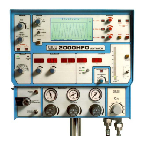
SLE 2000 HFO+ User manual

Issue
8
SLE 2000 HFO+
Ventilator
Service manual
High Frequency Oscillatory
Ventilator

Page 2 of 286 Issue 8
Contact Information:
All rights reserved. No part of this publication may be reproduced, stored in any retrieval system, or transmitted in
any form or by any means, electronic, mechanical, photocopy, recording or otherwise, without prior permission of
SLE. © Copyright SLE 04/01/2013
Manual : SM0010 Issue 8
SLE Part Nº: N2009/02
SLE Limited
Twin Bridges Business Park
232 Selsdon Road
South Croydon
Surrey CR2 6PL
Telephone: +44 (0)20 8681 1414
Fax: +44 (0)20 8649 8570
Web site: www.sle.co.uk

Issue 8 Page 3 of 286
Contents
1. Introduction ................................................................................................................. 10
1.1. How to use this manual...................................................................................... 10
1.2. The SLE2000 HFO+ Principles of Operation ..................................................... 10
2. Ventilator Control Description ................................................................................... 12
2.1. Front Panel......................................................................................................... 12
2.1.1. Front panel controls..................................................................................... 13
2.2. Back panel.......................................................................................................... 14
2.2.1. Back panel features..................................................................................... 14
2.3. Side panel........................................................................................................... 15
2.4. Electronic Module............................................................................................... 16
2.4.1. Electronic Module left hand side.................................................................. 16
2.4.2. Electronic Module right hand side................................................................ 17
2.5. Pneumatic Module without HFO NEEP.............................................................. 18
2.6. Pneumatic Module with HFO NEEP................................................................... 19
3. Accessing the SLE2000 HFO+ Internal Components .............................................. 22
3.1. Electronic Module............................................................................................... 22
3.2. Pneumatic Module.............................................................................................. 24
3.3. Separating the two modules............................................................................... 25
3.4. Removal of the Oxygen cell................................................................................ 27
3.4.1. Oxygen Cell Mounting ................................................................................. 27
3.5. Removal of the motor assembly......................................................................... 29
3.5.1. Motor Assemblies........................................................................................ 29
3.5.2. Removal of N2524/60 motor assembly........................................................ 30
3.5.3. Removal of N2524/61 motor assembly........................................................ 30
3.5.4. Removal of motor assemblies from pneumatic units fitted with HFO NEEP 32
4. Cleaning, Disinfection and Sterilization ................................................................... 36
4.1. Preparation of a new ventilator........................................................................... 36
4.2. Cleaning and disinfection of an in-service ventilator .......................................... 36
4.2.1. Cleaning, Disinfection & Sterilization chart.................................................. 37
4.3. Cleaning method ................................................................................................ 37
4.4. Disinfection method............................................................................................ 38
4.5. Sterilization method............................................................................................ 38

Page 4 of 286 Issue 8
5. Filter Systems .............................................................................................................39
5.1. Bacterial filter, SLE Part Nº:N2029 (Autoclavable).............................................39
5.2. Bacterial filter, SLE Part Nº:N2587 (Single use).................................................39
5.2.1. Precautions when using bacterial filter N2587.............................................39
6. Maintenance ................................................................................................................40
6.1. Monthly Operational Checks ..............................................................................40
6.1.1. Power Up Self Test ......................................................................................40
6.1.2. Air and Oxygen Supply Failure Alarm test...................................................40
6.1.3. Condition of O2Cell.....................................................................................40
6.1.4. PIP Pressure Check.....................................................................................41
6.1.5. CPAP pressure check..................................................................................41
6.1.6. HFO pressure check....................................................................................41
6.2. 6 Servicing..........................................................................................................42
7. Overhaul ......................................................................................................................44
8. Exchanging a Pneumatic Unit ...................................................................................46
9. SLE2000 HFO+ Set up and Calibration .....................................................................48
9.1. Recommended equipment .................................................................................48
10. Setup and calibration ...............................................................................................49
11. Operational Verification ............................................................................................66
11.1. Basic Operation ................................................................................................66
11.2. HFO Modulation................................................................................................68
11.3. Display Timebase .............................................................................................69
11.4. Display Pressure Range...................................................................................69
11.5. Freeze Push-Button..........................................................................................69
11.6. HFO Fail............................................................................................................69
11.7. FAN Fail............................................................................................................69
11.8. Slow Rise Waveform.........................................................................................69
11.9. PTV Mode.........................................................................................................70
11.10. SIMV Mode.....................................................................................................70
11.11. Block and Leak alarms....................................................................................70
11.12. Pressure Controls...........................................................................................71
11.13. Verification of HFO safety solenoid SV5.........................................................71
11.14. Verifying Pressure Drift Detection...................................................................72

Issue 8 Page 5 of 286
11.15. HFO NEEP Verification................................................................................... 72
11.16. Verification of AUX Output to the SLE2100VPM ............................................ 73
12. SLE2000 HFO+ Troubleshooting Chart ................................................................... 76
13. Technical Specification ............................................................................................ 82
13.1. Conventional Ventilation................................................................................... 82
13.2. HFO Ventilation ................................................................................................ 82
13.3. Displays............................................................................................................ 83
13.4. Controls............................................................................................................ 83
13.5. Alarms .............................................................................................................. 84
13.6. Power, Dimensions etc..................................................................................... 85
14. Circuit Descriptions .................................................................................................. 86
14.0.1. Front Panel Board Assembly (A0700/03).................................................. 86
14.0.2. LED Display Board Assembly (A0701/02)................................................. 86
14.0.3. Ventilator CPU Board Assembly (A0702/05)............................................. 86
14.0.4. HFO Main Board Assembly (A0736/04) .................................................... 87
14.0.5. Alarm Board Assembly (A0738/02) ........................................................... 89
14.0.6. Motor Drive Board Assembly (A0739/02).................................................. 90
14.0.7. Pressure Drift Monitor Board Assembly (A0745/01).................................. 91
14.0.8. Power Supply Unit..................................................................................... 92
14.0.9. Graphic LCD Module................................................................................. 92
14.1. Pneumatic Circuit ............................................................................................. 93
14.1.1. Pneumatic Layout for a standard HFO +................................................... 94
14.1.2. Pneumatic Layout for a HFO + with HFO NEEP ....................................... 95
14.1.3. Conventional Ventilation............................................................................ 96
14.1.4. HFO Operation .......................................................................................... 96
15. Circuit Details ............................................................................................................ 100
15.1. A0700/03 Display Board Assembly.................................................................. 100
15.1.1. CD/A0700/03 Display Board Circuit Diagram............................................ 101
15.2. A0701/02 LED PCB Assembly......................................................................... 103
15.2.1. CD/A0701/02 LED Board Circuit Diagram................................................. 104
15.3. AS/A0702/05 CPU PCB Issue 2 Sheet 1 of 2 ................................................. 107
15.3.1. AS/A0702/05 Issue 2 Sheet 2 of 2............................................................. 108
15.3.2. CD/A0702/05 CPU PCB Circuit Diagram Issue 2..................................... 109
15.4. AS/A0702/05 CPU PCB Issue 3 Sheet 1 of 2 .................................................. 114
15.4.1. AS/A0702/05 CPU PCB Sheet 2 of 2........................................................ 115

Page 6 of 286 Issue 8
15.4.2. CD/A0702/05 CPU PCB Circuit Diagram Issue 3......................................116
15.5. AS/A0702/05 CPU PCB Issue 3 Sheet 1 of 2 ..................................................121
15.5.1. Ventilator CPU Board (Detail A).................................................................122
15.5.2. CD/A0702/05 CPU PCB Circuit Diagram Issue 4......................................123
15.6. AS/A0736/04 Main PCB Revision E Issue 1 ...................................................129
15.6.1. CD/A0736/04 Main PCB Circuit Diagram Issue 1......................................130
15.7. AS/A0736/04 Main PCB Revision F Issue 2.....................................................134
15.7.1. CD/A0736/04 Main PCB Circuit Diagram Issue 2......................................135
15.8. AS/A0736/04 Main PCB Revision F Issue 3.....................................................139
15.8.1. CD/A0736/04 Main PCB Circuit Diagram Issue 3......................................140
15.9. AS/A0736/04 Main PCB Revision F Issue 3.....................................................144
15.9.1. CD/A0736/04 Main PCB Circuit Diagram Issue 4......................................145
15.10. AS/A0739/02 Motor Drive PCB Issue 1 Sheet 1 (Revision B)........................150
15.10.1. AS/A0739/02 Motor Drive PCB Issue 1 Sheet 2 (Revision B).................151
15.10.2. CD/A0739/03 Motor Drive PCB Circuit Diagram Issue 1 (Revision B) ....152
15.11. AS/A0739/02 Motor Drive PCB Issue 2 (Revision C) .....................................155
15.11.1. CD/A0739/03 Motor Drive PCB Circuit Diagram Issue 3. (Revision C) ...156
15.12. AS/A0756 HFO Start-up Motor PCB Issue 1..................................................159
15.13. AS/A0738/02 Alarm PCB Assembly...............................................................161
15.13.1. CD/A0738/02 Alarm PCB Circuit Diagram...............................................162
15.14. A0745/01 Pressure Drift Monitor Board..........................................................165
15.14.1. CD/A0745 Pressure Drift Board Circuit Diagram.....................................166
15.15. A0746 Flow Trigger PCB................................................................................168
15.16. CD/W0317 Wireloom Issue 2 .........................................................................171
15.17. CD/W0317 Wireloom Issue 3 .........................................................................172
15.18. CD/W0317 Wireloom Issue 4 .........................................................................173
15.19. Front Panel.....................................................................................................174
15.20. SK0057 Power Supply Wiring Diagram..........................................................175
15.21. CD/W0307 Electronic/Pneumatic Module interconnection.............................176
15.22. Electronic Chassis..........................................................................................177
15.23. Pneumatic Unit Assy. AS/L0263.....................................................................182
15.23.1. AS/L0263 Sheet 1 of 4 Issue 1................................................................182
15.23.2. AS/L0263 Sheet 2 of 4.............................................................................183
15.23.3. AS/L0263 Sheet 3 of 4.............................................................................184

Issue 8 Page 7 of 286
15.23.4. AS/L0263 Sheet 4 of 4............................................................................. 185
15.23.5. AS/L0263 Sheet 1 of 4 Issue 2................................................................ 191
15.23.6. AS/L0263 Sheet 2 of 4............................................................................. 192
15.23.7. AS/L0263 Sheet 3 of 4............................................................................. 193
15.23.8. AS/L0263 Sheet 4 of 4............................................................................. 194
15.23.9. AS/L0263 Sheet 1 of 4 Issue 3................................................................ 200
15.23.10. AS/L0263 Sheet 2 of 4........................................................................... 201
15.23.11. AS/L0263 Sheet 3 of 4........................................................................... 202
15.23.12. AS/L0263 Sheet 4 of 4........................................................................... 203
16. A3 Circuit Diagram Appendix .................................................................................. 209
17. Service Information and Technical Bulletins ......................................................... 232
17.1. Service Information .......................................................................................... 233
17.1.1. SI 990301 Calibration of Issue 2 of the A0745 Pressure Drift Board......... 233
17.1.2. SI 990302 Possible inadvertant solenoid failure messages ...................... 235
17.1.3. SI 990401 Slightly attenuated alarm sounder for the 12/24V monitor. ...... 236
17.1.4. SI 990801 Enhanced EMC........................................................................ 238
17.1.5. SI 000101 Modification of SLE 2000 HFO motor drive circuit board......... 243
17.1.6. SI 000201 Leak Alarm Trigger Threshold.................................................. 246
17.1.7. SI 000601 Addition of HFO NEEP............................................................. 248
17.1.8. SI 020901 Cleaning, Disinfection and Sterilisation of SLE ventilators....... 269
17.1.9. SI 060104 Replacement N2125 push button switches.............................. 270
17.2. Technical Bulletins............................................................................................ 272
17.2.1. TB 000201 New versions of control software............................................ 272
17.2.2. TB 000801 Ventilator Firmware Status...................................................... 273
17.2.3. TB 010201 New operational warnings....................................................... 276
17.2.4. TB 040401 V0226 Potentiometer .............................................................. 277
17.2.5. TB051101 Prevention of unintended oxygen leaks ................................... 278
18. Issue Revision Record ............................................................................................. 280
19. Index ........................................................................................................................... 281

Page 8 of 286 Issue 8
This page is intentionally blank.

Issue 8 Page 9 of 286
Introduction

Page 10 of 286 Issue 8
1. Introduction
1.1 How to use this manual
This manual contains chapters on how to maintain, service and overhaul the SLE 2000 HFO+
ventilator. It also contains information to set up and calibrate the ventilator to it original
specification.
Following the instructions in the relevant chapter will allow you to carry out one of the above
tasks. The manual contains circuit diagrams and descriptions of all the printed circuit boards.
To carry out routine maintenance refer to page 40.
To carry out a service refer to page 42.
To carry out an overhaul refer to page 44.
1.2 The SLE2000 HFO+ Principles of Operation
The SLE2000 HFO+ is based on the patented valveless ventilator design and can be operated
in conventional modes of ventilation.
When used as a High frequency oscillatory ventilator an additional flow of driving gas is
introduced into the exhalation block. This flow is supplied through a rotating shaft mounted on
a variable speed motor. This flow of driving gas is adjusted by the oscillatory pressure
regulator mounted in the pneumatic module ensuring a constant oscillatory pressure waveform
at all operating frequencies.
This rotating driving pressure produces oscillatory action in the patient circuit with an active
expiratory flow of gas. The oscillatory flow of gas is supplied from a separate rotating jet,
therefore it is possible to add the oscillations to the inspiration or expiration pressures. It is also
possible to add oscillations to the inspiratory plateau when operating the ventilator in any of the
Patient triggered modes of operation.
As in the SLE2000 and the SLE 2000HFO every care has been taken in the design to ensure
the safe operation of the ventilator. When in use the rotation of the motor is constantly being
monitored, should any malfunction be detected in the HFO+ operation the flow of oscillatory
driving gas will immediately be stopped, and the ventilator will display motor failure alarm. All
other functions of the ventilator such as micro-processors, fans, internal solenoids and front
panel controls are constantly being checked for correct operation.

Issue 8 Page 11 of 286
Ventilator Control
Description

Page 12 of 286 Issue 8
2. Ventilator Control Description
The SLE 2000 HFO+ consists of two linked modules, Electronic and Pneumatic.
2.1 Front Panel
Electronic
Module
Pneumatic
Module
1
2
3
456789
10
11
12
13
14
15
16
17
18
20
21
22
23
24
25
26
27
19

Issue 8 Page 13 of 286
2.1.1 Front panel controls
1) Power on and mode switch.
2) HFO mode switch.
3) HFO rate switch.
4) Display Freeze button.
5) Time control switch.
6) Display screen.
7) Low alarm adjustment control.
8) High alarm adjustment control.
9) Cycle fail alarm adjustment control.
10) Alarm Reset button.
11) Alarm mute button.
12) Manual breath button.
13) Flow/Pressure trigger switch.
14) Pressure wave selector switch.
15) Airway pressure monitoring selection switch.
16) PTV sensitivity control.
17) O2blender control.
18) O2inlet.
19) Medical air inlet.
20) Inspiratory pressure regulator.
21) Oscillator pressure regulator.
22) CPAP/PEEP pressure regulator.
23) Fresh gas to patient port.
24) Exhalation block.
25) Pressure monitoring port.
26) Inspiration time control.
27) Breaths per minute (BPM) control.

Page 14 of 286 Issue 8
2.2 Back panel
2.2.1 Back panel features
1) Auxiliary Output.
2) FIO2Calibration adjustment.
3) Running time meter - pneumatic module.
4) Fuse holders.
5) Product information plate.
6) FIO2Adjustment Tool.
7) Fan and Filter.
8) Filter only.
12
3
4
5
6
7
8

Issue 8 Page 15 of 286
2.3 Side panel
1) Fixed jet
2) Rotating jet
Note: Exhalation block removed
2
1

Page 16 of 286 Issue 8
2.4 Electronic Module
2.4.1 Electronic Module left hand side
Board positions within the electronic unit viewed from the left.
Position of the boards within the electronic module.
1) HFO+ Main Board Assembly (A0736/04)
2) Ventilator CPU Board Assembly (A0702/05)
3) Motor Drive Board Assembly (A0739/02)
Note: Boards 1,2, and 3 are polarised by the position of the edge connectors thus preventing
the boards being inserted into the wrong sockets.
3
2
1

Issue 8 Page 17 of 286
2.4.2 Electronic Module right hand side
Board positions within the electronic unit viewed from the right
4) Alarm Board Assembly (A0738/02)
5) Pressure Drift Monitor Assembly (A0745)
6) Front Panel Board Assembly (A0700/03) and LED Display Board Assembly (A0701/
02). Note: both these boards are mounted on the rear face of the front panel.
5
4
6

Page 18 of 286 Issue 8
2.5 Pneumatic Module without HFO NEEP
1) Motor assembly (N2524/60 Shown).
2) NEEP adjusting block.
3) SV5 Solenoid valve (Beneath bracket)
4) SV4 Solenoid valve (HFO solenoid valve).
5) SV3 Solenoid valve.
6) SV2 Solenoid valve.
7) SV1 Solenoid valve.
8) Volume chamber.
9) Blender.
10) Regulator (Reg 3)
Regulator 3 test point
indicated by arrow
11) PAPST "L" fan.
12) 25 way plug.
13) O2cell manifold
1
2
8
9
11
10
13
5
6
7
4
12
3

Issue 8 Page 19 of 286
2.6 Pneumatic Module with HFO NEEP
1) Motor assembly (N2524/61 Shown).
2) NEEP adjusting block.
3) SV5 Solenoid valve (Beneath bracket)
4) SV4 Solenoid valve (HFO solenoid valve).
5) SV3 Solenoid valve.
6) SV2 Solenoid valve.
7) SV1 Solenoid valve.
8) Shuttle Valve.
9) Volume chamber.
10) Blender.
11) Regulator (Reg 3)
Regulator 3 test point indi-
cated by arrow
12) PAPST "L" fan.
13) 25 way plug.
14) O2cell manifold
1
2
9
10
12
11
14
5
6
7
4
13
3
8

Page 20 of 286 Issue 8
This page is intentionally blank.
Table of contents
Other SLE Fan manuals
Popular Fan manuals by other brands

Air Vent Inc.
Air Vent Inc. WH242ML installation instructions

Reymsa
Reymsa RT-404 Installation, operation & maintenance manual

Goldair
Goldair GHL255W operating instructions

Swegon
Swegon DOMO C Installation, commissioning maintenance

Lasko
Lasko R12210 Instructions and operating manual

Excellent Electrics
Excellent Electrics DX5-000030 Instructions for use