Sliger SV590 User manual

SV590
Vertical Mini-ITX PC Case - Build Guide

RED M3 x 5mm FLAT HEAD
Power Cord Mount Bracket
SSDs / SSD brackets
PINK M3 x 8mm FLAT HEAD
Power Cord
GREEN M3 x 6mm PAN HEAD
Securing PCIe Cards
VIOLET 6-32 x 1/4” HEX HEAD
Motherboard
Power Supplies
BLUE 6-32 x 1/4” FLAT HEAD
Side Panels
Case Frame Assembly
3.5” Hard Drives
Base Plate (Optional)
SCREWS
The SV590 comes with a total of 5 dierent screws.
For the purposes of this guide we will assign a unique color to each
of the screws, signifying their locations through out this guide.

The SV590s top and bottom covers
feature tool-less removal via ball-
stud mounting points. This feature
allows for convenient access to your
motherboard and PCIe card IO ports
regardless of case orientation.
The top and bottom panels can also
be reversed onto either end of the
case, allowing the “cable cubby”
side to face up or down.
Note: these panel may be very tight
on the rst few times on/o!
TOOL-LESS END CAPS

SIDE PANELS
Panels on the SV590 are attached via a total of 12x 6-32 X 1/4” FLAT HEAD.
Four per panel with three panels total (front panel + two side panels).
APhillips #2 size screw driver is required for these screws.
(Screw driver tip should match size of cut in the screw. If you use
an undersized driver you risk stripping the screw head!)

CASE FRAME
The rear radiator mount bracket of the SV590 frame is held on by
6x 6-32 X 1/4” FLAT HEAD screws; two on each side of the cable cubby,
and one on each side at the opposite end of the case.

POWER CORD
The power cord extension is then installed into the mount bracket with
2x M3 x 8mm FLAT HEAD screws. After that, the power cord and bracket should be
attached and the power should be routed through the grommet. It may be attached
to the case frame via 2x M3 x 5mm FLAT HEAD screws at any of the viable mount
locations. The bracket can be positioned to where it least obstructs the
motherboard or GPU ports. Make sure to point the open end of the inlet towards the
rear of the case!
The SV590 includes an internal power cord extension, protective grommet, and
mount bracket for routing the power supply inlet into the"cable cubby" of the case
frame. Clip the Cable Grommet onto the power cord before you install it into the
case. Then run the cord through the cutout located above the PCIe card tab cutout,
and nally slide the grommet into position as shown below.

POWER BUTTON
New for V2 of the SV590 is the
ability to mount the power
button to either end of the case
frame.
With V2, the power button is
attached to a small bracket
which can be relocated to either
mounting position. This bracket
is secured to either end of the
case with 2x M3 x 5mm FLAT
HEAD screws.
When the power button is
mounted on the “cable cubby”
end of the case frame you will
need to pass the button cable &
connectors through the hole
and grommet located next to the
motherboard IO Shield cutout (A).
(A)

A Phillips #2 screw driver with a minimum 3” shaft length is recommended for
installing these screws. Both of the screws on the PCIe slot side of the motherboard
have pass-through holes in the case frame to allow the screw driver and screw to
pass through and be screwed in straight.
Additional installation instructions for your CPU, CPU cooler, RAM, etc. are covered by
your motherboard or coolers respective user manual.
Don’t forget to install the power
cord and your IO shield rst!
Some CPU coolers may require a
back plate installed before installing
the motherboard into the case.
It is advised to also check that any
M.2 mounts on the back of the
motherboard have drives installed
before mounting the motherboard.
Once the IO shield and power cord
with grommet are properly installed,
the motherboard can now
be mounted using 4x 6-32 x 1/4”
HEX HEAD screws.
MOTHERBOARD

POWER SUPPLY
NOTE: The fan on the power supply is recommended to be positioned with the
fan side pointed towards the center spine of the case. This
orientation will result in better overall system temperatures and lower noise.
Once positioned, the SFX PSU can be attached to the PSU Mounting Bracket
with up to 6x of the included 6-32 x 1/4” HEX HEAD screws.
Note: that not all SFX Power Supplies have all 6x screw holes as shown.

POWER SUPPLY CONT.
Note: The fan on the power supply is recommended to be positioned with the
fan side pointed towards the center spine of the case. This
orientation will result in better overall system temperatures and lower noise.
Once positioned, PSU alternative mounting bracket can be attached to the chassis
with 2x
6-32 X 1/4” FLAT HEAD
screws.
Then an SFX or SFX-L PSU can be attached to the alternative mounting bracket
with up to 6x of the included 6-32 x 1/4” HEX HEAD screws.
Note: that not all SFX Power Supplies have all 6x screw holes as shown.
SFX with alternative PSU Bracket SFX-L with alternative PSU Bracket

SSDs and HDDs
This is our RECOMMENED SSD layout on the front rail of the chassis. 4x 2.5" SSDs can
be installed with 2x
M3 x 5mm FLAT HEAD screws per drive.
Note: The lower 2 SSDs can NOT be used when you have DDC Pump mounted.

Our SV590 has multiple 3.5" HDD and 2.5" SSD mounting locations.
Shown below are various HDD and SSD congurations.
SSD and HDDs
Note : Can t up to 5 SSD drives under the PSU ONLY if
an SFX PSU is mounted to the alternative PSU mounting
bracket (A). *Will not work with a SFX-L PSU*
For any of the bottom-of-case
SSD mounts the SATA power
and SATA data cable must face
away from the radiator & fans.
Each 2.5" SSD on the bottom of
the case is mounted via 2x M3 x
5mm FLAT HEAD screws into
the side of the respective 2.5"
SSD.
(A)

SSDs and HDDs (cont)
3.5” Hard Drive Disks should be mounted with 2x 6-32 X 1/4” FLAT HEAD screws.
2x 3.5” Hard Drive Disks
Note: 3.5" HDD limits the maximum GPU length to 290mm

CABLE MANAGEMENT
Once the motherboard and power
supply are mounted, it is recommended
to do some cable management before
we install any radiators or PCIe cards.
Note: the CPU and cooler mount back
plate / standos are installed.
The power switch/LED is routed and
plugged into the motherboard.
The power cord is mounted at top
(two screws in counter sinks) and
properly passed through the
grommet, and routed to the inlet on
the power supply.
(Also be sure to check that your PSU
switch is set to on!)
Motherboard power cables are
plugged in, and GPU power cables are
loosely positioned.
Power cables are loosely managed
and zip tied.
The PCIe riser is plugged into the
PCIe slot on the motherboard.

GPU MOUNTING
Process of installing the GPU is same
it would be on a standard PC case,
just on a PCIe riser. Slide the card
into position, push down into the
slot, and then secure the PCIe card
bracket with the M3 x 6mm PAN
HEAD screws.
If your GPU only has a 2-slot wide
PCIe bracket. The SV590 includes a
single-color matched slot cover.
We recommend installing the GPU after
installing the radiator as the case will be
slightly more rigid.
Additionally this method allows access
to the fan screws for ease of installing
fan guards, reversing fan airow, etc.

240mm / 120mm AIO
ALL FANS MUST BE SET TO EXHAUST OUT THE REAR OF THE CASE
If fans are installed as intake you will cause your power supply and GPU to
run at high temperatures, which may cause part failures.
The compact design of the SV590 limits the
ways in which dual AIO setups can be installed.
The 240mm AIO (A) at left, shown in orange,
must be mounted above the 120mm AIO with
the radiator hoses facing downward.
The 120mm AIO (B) must be mounted below the
240mm AIO, with the 120mm AIO hoses able to
be oriented to the top or bottom of the case.
If the 240mm AIO hoses are mounted to the top,
you will not be able to screw the case together -
as the hoses will hit the motherboard and/or
GPU.
Conversely, if the AIOs are mounted as shown,
the hoses will come out where there is
additional free space next to the power supply /
below the GPU/PCIe cards.
If your AIOs do not include mounting screws,
please use the 6-32 x 1/4” HEX HEAD screws
provided with the case.
(B)
(A)

360mm AIO
ALL FANS MUST BE SET TO EXHAUST OUT THE REAR OF THE CASE, If fans
are installed as intake you will cause your power supply and GPU to run at
higher temperatures.
If the 360mm radiator hoses are mounted to the top, you will not be able to screw
the case closed as the hoses will collide with the motherboard and/or GPU PCIe
riser bracket. Conversely, if the AIO is mounted as shown to the bottom of the case,
the hoses will not have interference issues due to free space around the power
supply and below the GPU. If your AIOs did not include mounting screws, please
use the 6-32 x 1/4” HEX HEAD screws provided with the case.

CASE REASSEMBLY
With the radiator/AIO in position
your case should look like the example
to the right, minus your GPU and
any 2.5” SSD / 3.5” HDDs.
To attach the AIO/radiator, the back panel must be reinstalled from disassembly
on page 5 in this guide. The rear radiator mount bracket to the SV590 frame is
held on by 6x 6-32 x 1/4" FLAT HEAD screws.
We recommend plugging in your fan
headers / fan splitters before
screwing the rear radiator bracket
back onto the case frame.
It is also recommended to try various
positions of the CPU AIO pump block
to best t the hoses as lengths can
vary.

DDC PUMP RESERVOIR
Location 2Location 1
Location 3
DDC Pump attached to bracket with
4x M4 x 5mm FLAT HEAD screws
and then whole assembly attached
to the chassis with 2x
M3 x 5mm FLAT HEAD screws.
DDC Pump attached to the chassis
above the PSU with 3x M4 x 5mm
FLAT HEAD screws.
DDC Pump attached to the chassis below
GPU with 4x M4 x 5mm FLAT HEAD screws.
NOTE: This mounting location limits the GPU
card length. Be sure to double check your
measurements. 390mm - (Total height of
Pump/Res. in mm) = Max GPU Length.
The SV590 has multiple DDC Pump / Reservoir mounting locations which are
shown below
Other manuals for SV590
2
Table of contents
Other Sliger Enclosure manuals
Sliger
Sliger CERBERUS Manual
Sliger
Sliger SV540 User manual
Sliger
Sliger SM5X0 Series User manual
Sliger
Sliger S610 User manual
Sliger
Sliger S620 User manual
Sliger
Sliger SM580 User manual
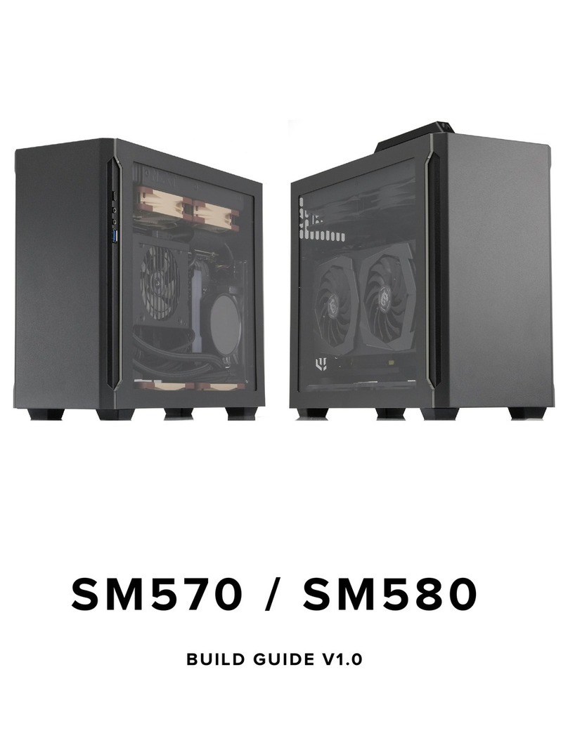
Sliger
Sliger SM570 User manual
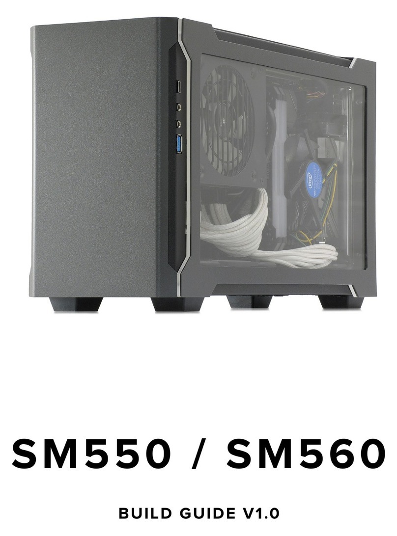
Sliger
Sliger SM550 User manual
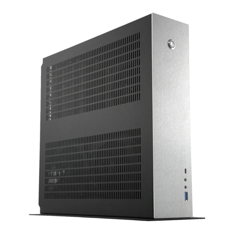
Sliger
Sliger CL530 User manual

Sliger
Sliger SM5X0 Series User manual
Popular Enclosure manuals by other brands
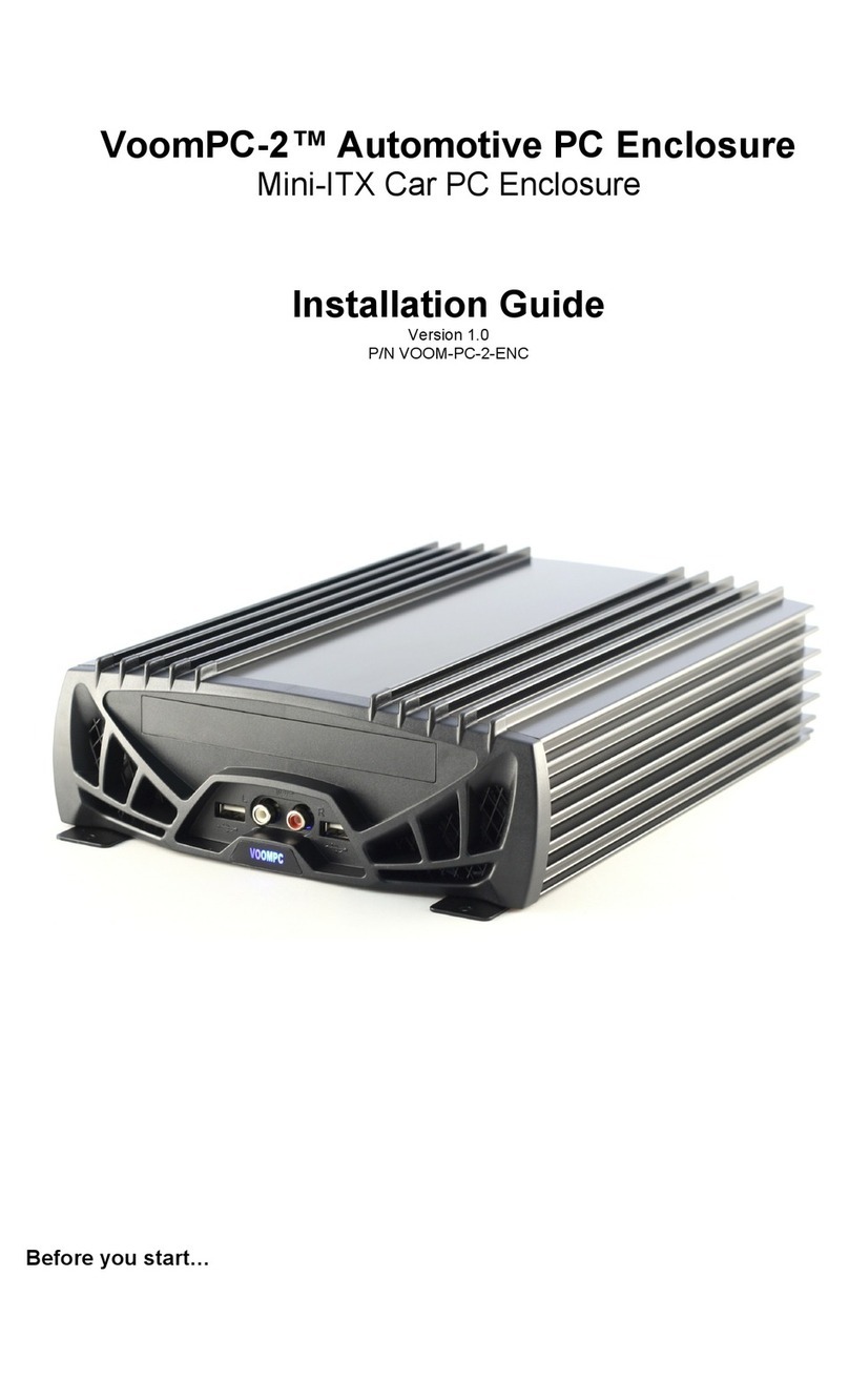
Curtis Computer
Curtis Computer Automotive PC Enclosure VoomPC-2 installation guide
Wheelock
Wheelock EN4 installation instructions
Rockford Fosgate
Rockford Fosgate PUNCH P500-12P quick start guide
BE QUIET!
BE QUIET! Silent base 600 user manual

Lenovo
Lenovo ThinkAgile VX3720 7Y12 user guide
Vantec
Vantec NexStar 3 user manual

