SlimLine SLTLU User manual

ISSUED: 11-30-09 SHEET #: 202-9417-1
©
UL
USC
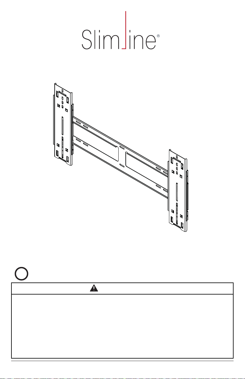
Slimline Ultra-Thin Tilt Mount
for 37" to 60" LCD Flat Panel Screens
Max UL Load Capacity: 100 lb (45.4 kg)
Model: SLTLU
Installation Guide
This product was designed to be installed on wood stud walls and solid concrete (2000 psi density
minimum) or cinder block walls. Before installing make sure the supporting surface will support the
combined load of the equipment and hardware. Screws must be tightly secured. Do not overtighten screws
or damage can occur or product may fail. Never exceed the Maximum UL Load Capacity. This product
is intended for indoor use only. Use of this product outdoors could lead to product failure or personal
injury. Depth of screen must be less than 2". This mount is designed to attach the screen 0.68" from the
wall. Please refer to manufacturer's installation guide recommendations for required distance from wall
to avoid risk of injury or property damage. For support please call customer care at 1-800-865-2112.
WARNING

2 of 52 ISSUED: 11-30-09 SHEET #: 202-9417-1
A (1)
B (2)
Tools Needed for Assembly
recommended)
phillips screwdriver
drill
level
hammer (optional)

3 of 52 ISSUED: 11-30-09 SHEET #: 202-9417-1
C(6)
E(6)
M4 x 12 mm
D(6)
F(4)
M4 x 25 mm G(4)
M5 x 12 mm
H(4)
M5 x 25 mm
I(4)
M6 x 12 mm J(4)
M6 x 20 mm K(4)
M6 x 25 mm L(4)
M6 x 30 mm
M(6)
M8 x 16 mm
N(4)
M8 x 25 mm O(4)
M8 x 40 mm
T(1)
P(4)
ID .219" (5.56 mm)
Q(4)
ID .344" (8.74 mm)
R(6)
S(1)

4 of 52 ISSUED: 11-30-09 SHEET #: 202-9417-1
Installing on Wall with Two Wood Studs
1
Use wall plate (A) as a template, make sure it is level, and mark four mounting holes along the center
A) and
attach to wall with four wood screws (C
A
C
Do not over tighten screws, or damage may occur.
WARNING
C
ATOP CUTAWAY VIEW
Wood screws must
center in stud
STUD
WARNING

5 of 52 ISSUED: 11-30-09 SHEET #: 202-9417-1
Installing on Wall with Three Wood Studs
1
Use wall plate (A) as a template, make sure it is level, and mark six mounting holes along the center
A) and
attach to wall with six wood screws (C
C
A
Do not over tighten screws, or damage may occur.
WARNING
C
ATOP CUTAWAY VIEW
Wood screws must
center in stud
STUD
WARNING

6 of 52 ISSUED: 11-30-09 SHEET #: 202-9417-1
Installing to Solid Concrete or Cinder Block
1
Level wall plate (A
D) into holes and secure wall plate
(A) with six screws (C
C
A
D
SOLID CONCRETE
CINDER BLOCK

7 of 52 ISSUED: 11-30-09 SHEET #: 202-9417-1
Drill holes and insert anchors (D).
concrete surface
1D
Place plate (A) over anchors (D). Secure with screws (C). Tighten screws.
A
D
C
2
anchors. Do not drill into mortar joints! Be sure to mount in a solid part of the block, gener-
ally 1" (25 mm) minimum from the side of the block. Cinder block must meet ASTM C-90
hole instead of a hammer drill to avoid breaking out the back of the hole when entering a
void or cavity.
directly to load-bearing concrete.
WARNING
CUTAWAY VIEW
INCORRECT
CORRECT
drywall
wall plate
wall plate
concrete
concrete
drywall
WARNING
8 of 52 ISSUED: 11-30-09 SHEET #: 202-9417-1
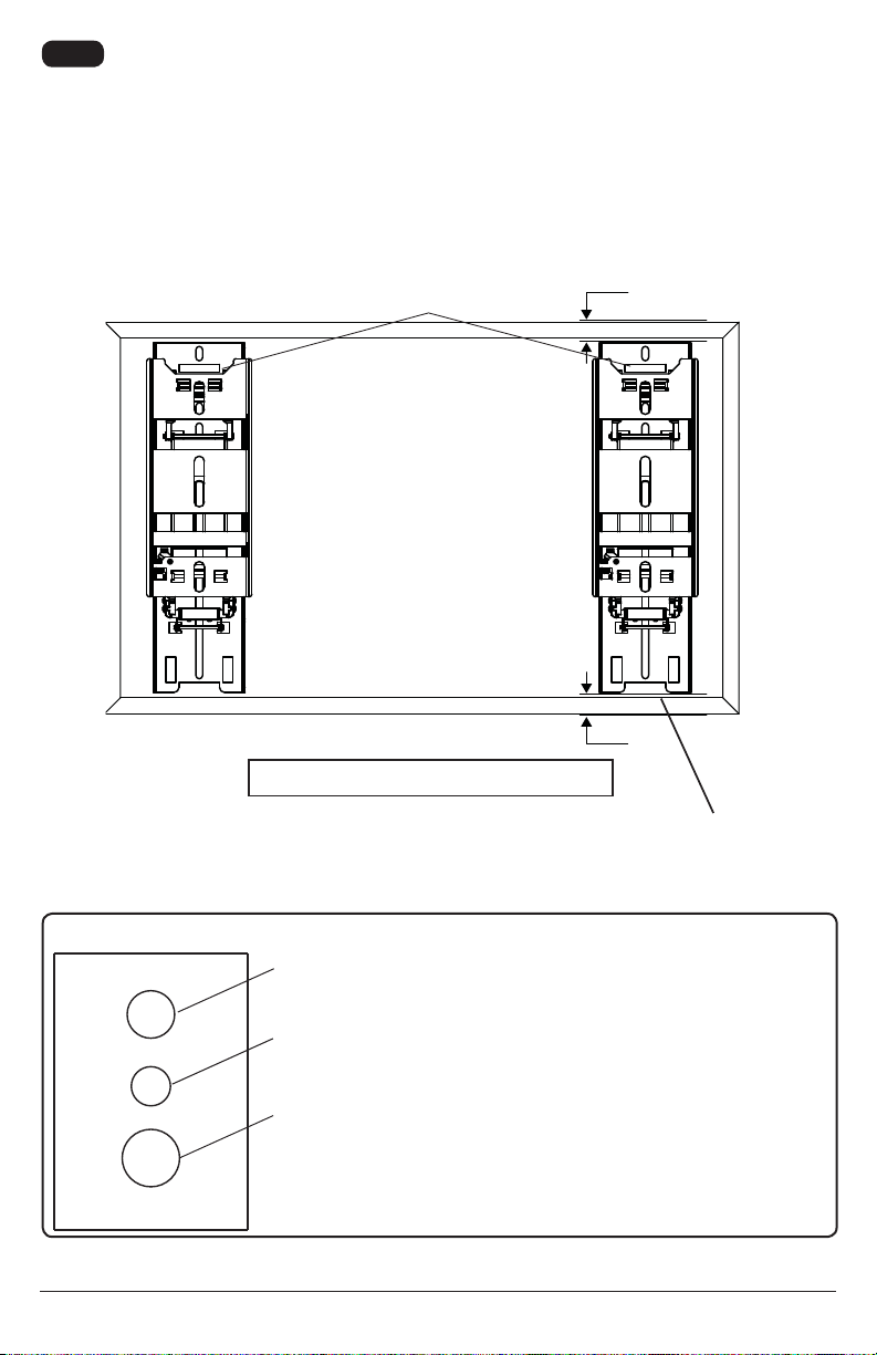
Installing Tilt Brackets
If screen has obstructions on the back, remove them to allow the tilt brackets to be attached. Fully extend
tilt brackets (B) and place tilt brackets on back of screen. Align to holes, and center vertically on back of
screen as shown below. Attach the tilt brackets to the back of the screen using the appropriate combination of
screws, washers, and spacers as required
shown in steps 2-1 or 2-2.
NOTE: Top and bottom holes must always be used.
Verify that tilt brackets are properly aligned and then tighten screws using phillips screwdriver.
2
X
X
B
CENTER
BRACKETS
VERTICALLY
ON BACK OF
SCREEN
NOTE: "X" dimensions should be equal.
NOTE: Cut outs indicate
bottom of tilt brackets (B)
Notes:
depending upon the type of screen.
used, depending upon the type of screen.
washer that matches your screw size.
MEDIUM HOLE
FOR M5 SCREWS
SMALL HOLE
FOR M4 SCREWS
LARGE HOLE
FOR M6 SCREWS
MULTI-WASHER

9 of 52 ISSUED: 11-30-09 SHEET #: 202-9417-1
For Flat Back Screens
For Bump-Out or Recessed Back Screens
Begin with the shortest length screw, hand thread through multi-washer, tilt bracket and
spacer, if required, into screen as shown below. If screw cannot make three full turns into the
Repeat for remaining mounting holes, level brackets and tighten screws.
NOTE: Spacers may not be used depending on the type of screen.
NOTE: If screen manufacturer's requirements state that more than 0.68" of ventilation is
required, spacers may be used to add an additional 0.5" (spacer P) or 0.75" (spacer Q) of
space between the wall and the screen as shown below.
Begin with the shortest length screw, hand thread through multi-washer , tilt bracket and
spacer as required into screen as below. If screw cannot make three full turns into the screen
for remaining mounting holes, level brackets and tighten screws.
If you have any questions, please call Peerless customer care at 1-800-865-2112
2-1
2-2
If you have any questions, please call Peerless customer care at 1-800-865-2112
SCREEN
SPACER
MULTI-WASHER
SCREW
TILT BRACKET (B)TILT BRACKET (B)
SCREEN
MULTI-WASHER
SCREW
SCREEN
SPACER
SCREW
TILT BRACKET (B)
bracket is still not tightly secured, damage may occur to screen or product may fail.
WARNING
MULTI-WASHER
10 of 52 ISSUED: 11-30-09 SHEET #: 202-9417-1
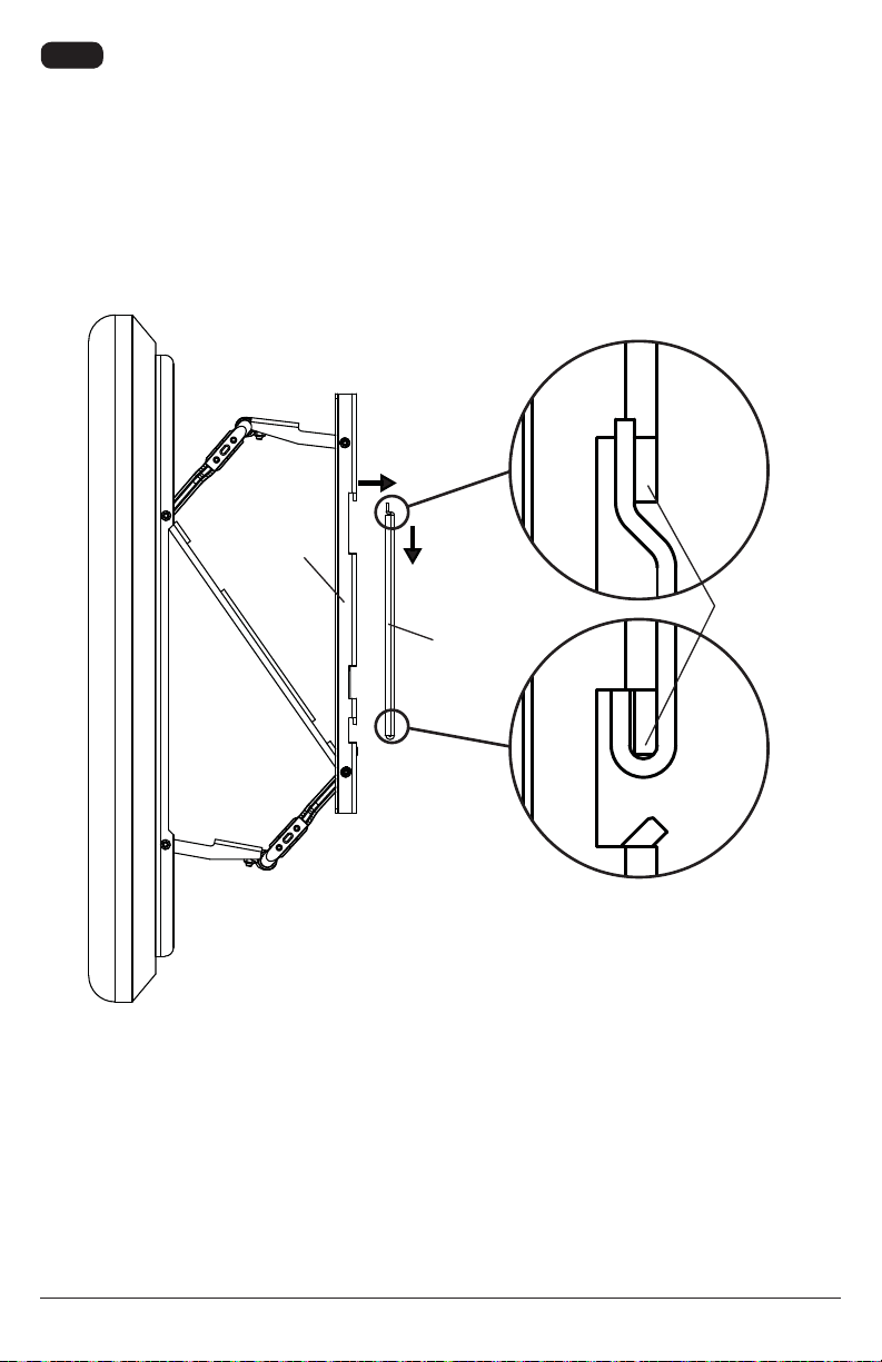
Mounting the Flat Panel Screen
3
Fully extend tilt brackets (B) and move tilt brackets toward wall plate (A
-
DETAIL 1
FLANGES
B
B
B
A

11 of 52 ISSUED: 11-30-09 SHEET #: 202-9417-1
Tighten safety screws using allen wrench (T) to lock down safety latches securing tilt
brackets to wall plate as shown in detail 2. Reverse steps 3 and 4 to remove screen.
DETAIL 2
SAFETY
LATCH
WALL
PLATE
SAFETY
SCREW
B
4
Failure to lock brackets (B) with safety
screws can cause sceen to come off mount
if hit accidentally.
WARNING
12 of 52 ISSUED: 11-30-09 SHEET #: 202-9417-1
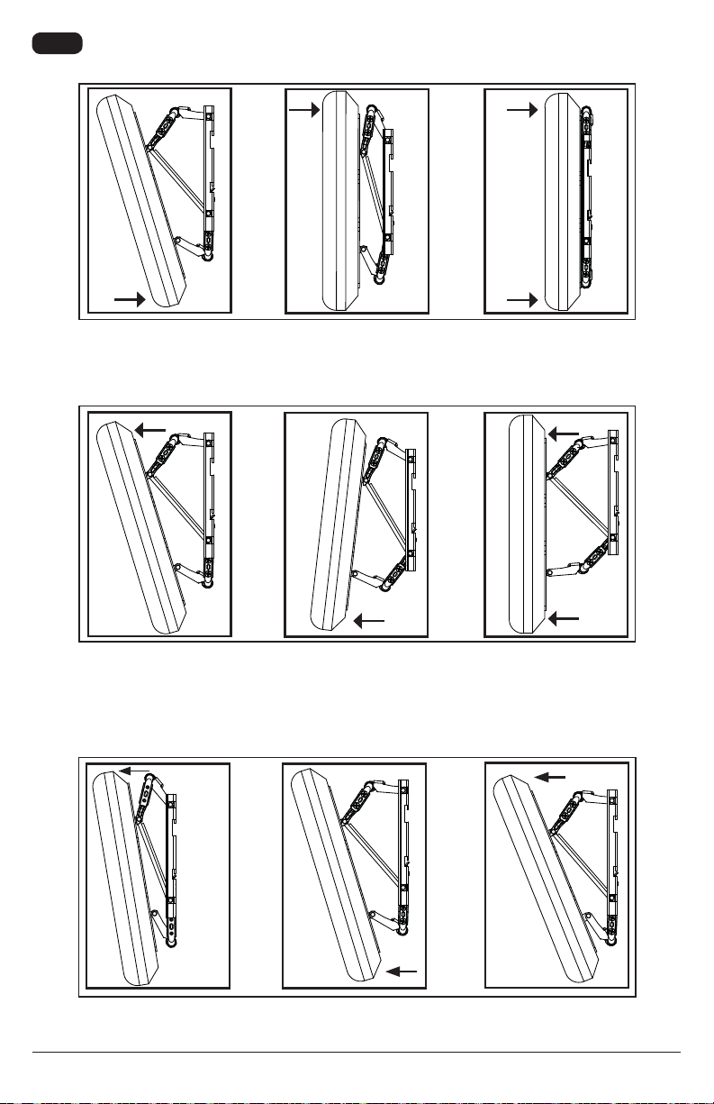
5To collapse adapter plate, grasp top and bottom of screen, push bottom of screen toward
wall then push top of screen toward wall.
132
12 3
13
2
Tilt option: From the collapsed position, pull from top to achieve up to 15° of forward tilt. For
more tilt adjustment, slightly pull out bottom and pull from top to desire tilt angle.
To extend adapter plate and access back of screen, grasp top and bottom of screen, pull
top of screen away from wall then pull bottom of screen away from wall.
PUBLICADO: 11-30-09 HOJA #: 202-9417-1
Modelo: SLTLU
Guía para la instalación
Soporte inclinación Slimline Ultra-Thin
para pantallas planas LCD de 37" à 60"
Máxima capacidad (UL) de carga: 100 lb (45.4kg)
©
UL
USC
Este producto está diseñado para ser instalado en paredes con montantes de madera y en paredes
de concreto macizo (de una densidad mínima de 2,000 psi) o de bloques de hormigón. Antes de
Máxima (UL) de Carga. Este producto está diseñado para uso en interiores solamente. Utilizar este
producto en exteriores podría causar fallas del producto o lesiones a individuos. La profundidad de
la pantalla tiene que ser menos de 2". Este soporte está diseñado para sostener la pantalla a 0.68"
de la pared. Por favor, repase las recomendaciones del manual de instalación del fabricante con
respecto a la distancia necesaria de la pared para evitar el riesgo de sufrir lesiones o causar daños a
la propiedad. Si necesita ayuda, por favor, llame a Servicio al Cliente de Peerless al 1-800-865-2112.
ADVERTENCIA

14 de 52 PUBLICADO: 11-30-09 HOJA #: 202-9417-1
Español
Herramientas necesarias para el ensamblaje
recomienda uno de "borde a borde")
montantes de madera
o de bloques de hormigón de escorias
A (1)
B (2)

15 de 52 PUBLICADO: 11-30-09 HOJA #: 202-9417-1
Español
C(6)
E(6)
M4 x 12 mm
D(6)
F(4)
M4 x 25 mm G(4)
M5 x 12 mm
H(4)
M5 x 25 mm
I(4)
M6 x 12 mm J(4)
M6 x 20 mm K(4)
M6 x 25 mm L(4)
M6 x 30 mm
M(6)
M8 x 16 mm
N(4)
M8 x 25 mm O(4)
M8 x 40 mm
T(1)
P(4)
ID .219" (5.56 mm)
Q(4)
ID .344" (8.74 mm)
R(6)
S(1)

16 de 52 PUBLICADO: 11-30-09 HOJA #: 202-9417-1
Español
A
C
Instalar en una pared con dos montantes de madera
1
Utilice la placa de pared (A) como plantilla, asegúrese de que esté nivelada y marque cautro
agujeros de montaje a lo largo de las líneas que pasan por el centro de los montantes de madera.
de pared (A) y fíjela a la pared con cautro tornillos de madera (C) en el centro del montante.Se
No apriete los tornillos en exceso.
Pernos largos en el
centro del montante
C
A
dañar.
ADVERTENCIA ADVERTENCIA
VISTA SUPERIOR EN CORTE
MONTANTE

17 de 52 PUBLICADO: 11-30-09 HOJA #: 202-9417-1
Español
1
Utilice la placa de pared (A) como plantilla, asegúrese de que esté nivelada y marque seis agujeros
de montaje a lo largo de las líneas que pasan por el centro de los montantes de madera. Taladre seis
A) y
fíjela a la pared con seis tornillos de madera (C) en el centro del montante. Se recomienda utilizar un
en exceso.
Instalar en una pared con tres montantes de madera
C
A
Pernos largos en el
centro del montante
C
A
dañar.
ADVERTENCIA ADVERTENCIA
VISTA SUPERIOR EN CORTE
MONTANTE

18 de 52 PUBLICADO: 11-30-09 HOJA #: 202-9417-1
Español
1Instalar en una pared de concreto
Nivele la placa de pared (A) y úsela como plantilla para marcar cautro agujeros de montaje. Taladre
anclajes (DA) a la pared con seis pernos largos (C). Apriete
C
A
D
CONCRETO MACIZO
BLOQUE DE HORMIGÓN
DE ESCORIAS

19 de 52 PUBLICADO: 11-30-09 HOJA #: 202-9417-1
Español
Perfore los agujeros y después inserte los anclajes (D).
concreto macizo
1D
Coloque la placa (A) sobre los anclajes (D), fíjela con los tornillos (C). Apriete
los tornillos.
A
D
C
2
-
(35 mm) en el agujero, que pueda usar para los anclajes para concreto. ¡No taladre en
juntas de argamasa! Asegúrese de hacer la instalación en la parte sólida del bloque, por lo
general, a un mínimo de 1" (25 mm) del extremo del bloque. Los bloques de hormigón de
taladro eléctrico convencional a baja velocidad para hacer el agujero en vez de un taladro
percutor para no perforar el fondo del agujero al entrar en un vacío o una cavidad.
ADVERTENCIA
INCORRECTO
CORRECTO
placa de
pared
concreto
concreto
ADVERTENCIA
VISTA EN CORTE
de yeso-cartón
de yeso-cartón
placa de
pared

20 de 52 PUBLICADO: 11-30-09 HOJA #: 202-9417-1
Español
Instalación de los soportes inclinables
-
clinables. Extienda los soportes inclinables (B) completamente y colóquelos en la parte trasera de
la pantalla. Centralícelos verticalmente con los agujeros en la parte trasera de la pantalla, como se
muestra abajo. Fije los soportes inclinables en la parte trasera de la pantalla utilizando la combi-
nación adecuada de tornillos, arandelas y espaciadores necesarios, como se muestra en el paso 2-1
o en el paso 2-2.
NOTA: Siempre se tienen que usar los agujeros superiores y los inferiores.
usando un destornillador phillips.
2
X
X
B
CENTRE LOS
SOPORTES
VERTICALMENTE
EN LA PARTE
TRASERA DE LA
PANTALLA
NOTA: Las dimensiones "X" deben ser iguales.
NOTA: Los extremos recorta-
dos indican la parte inferior de
los soportes inclinables (B).
Notas:
según el tipo de pantalla.
arandelas múltiples y los espaciadores,
dependiendo del tipo de pantalla.
arandela múltiple que coincida con el tamaño
de su tornillo.
AGUJERO
MEDIANO PARA
TORNILLOS M5
AGUJERO PEQUEÑO
PARATORNILLOS M4
AGUJERO GRANDE
PARA TORNILLOS M6
ARANDELA MÚLTIPLE
Table of contents
Languages:
Other SlimLine TV Mount manuals


