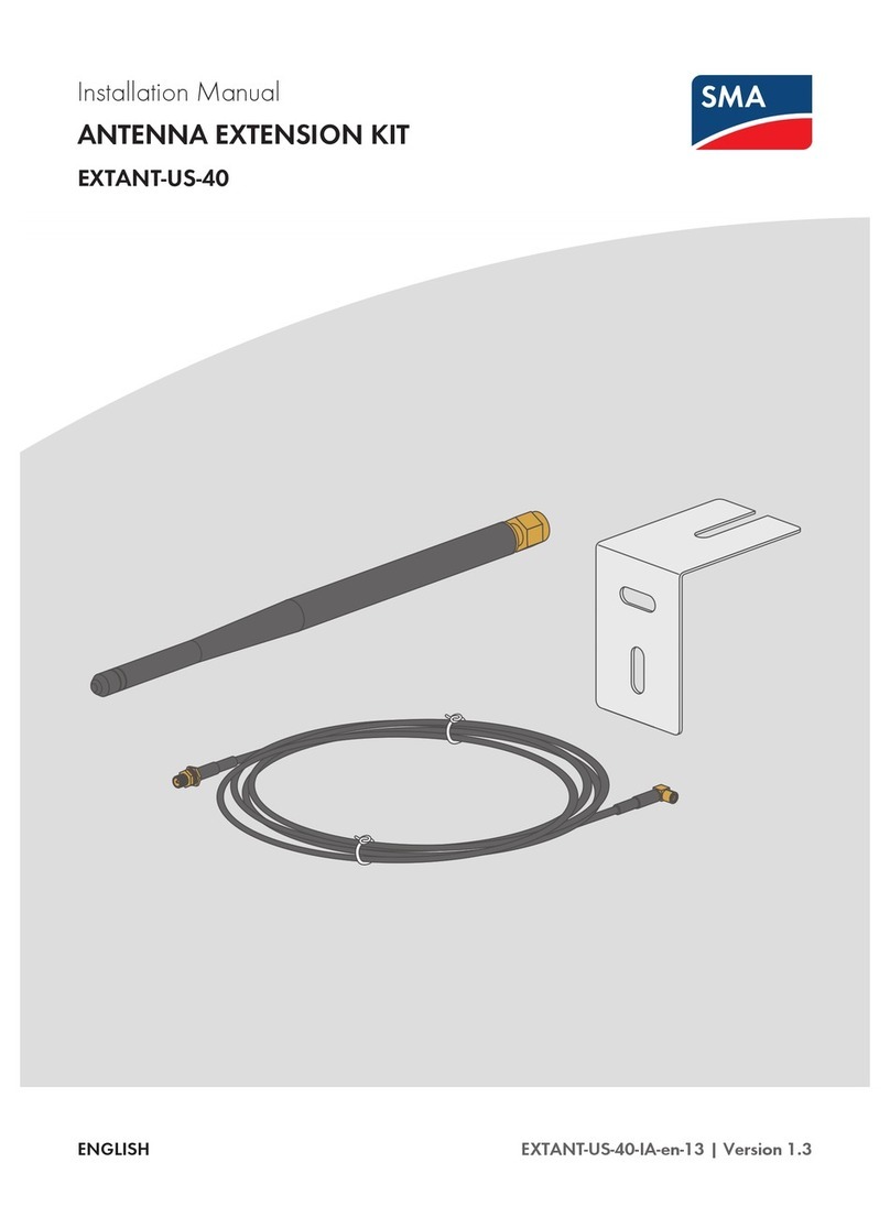
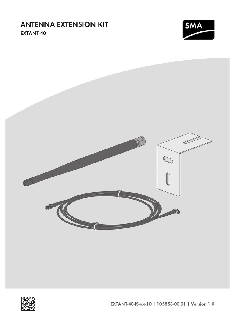
SMA ANTENNA EXTENSION KIT User manual

Installation Manual
ANTENNA EXTENSION KIT
EXTANT-40-IA-en-10 | Version 1.0ENGLISH

Legal Provisions
The information contained in these documents is property of SMA Solar Technology AG. Any publication, whether in
whole or in part, requires prior written approval by SMA Solar Technology AG. Internal reproduction used solely for
the purpose of product evaluation or other proper use is allowed and does not require prior approval.
SMA Warranty
You can download the current warranty conditions from the Internet at www.SMA-Solar.com.
Trademarks
All trademarks are recognized, even if not explicitly identified as such. Missing designations do not mean that a
product or brand is not a registered trademark.
Modbus® is a registered trademark of SchneiderElectric and is licensed by the ModbusOrganization,Inc.
QRCode is a registered trademark of DENSOWAVEINCORPORATED.
Phillips® and Pozidriv® are registered trademarks of PhillipsScrewCompany.
Torx® is a registered trademark of AcumentGlobalTechnologies,Inc.
SMA Solar Technology AG
Sonnenallee 1
34266 Niestetal
Germany
Tel. +49 561 9522-0
Fax +49 561 9522-100
www.SMA.de
Email: [email protected]
Status: 3/13/2017
Copyright © 2017 SMA Solar Technology AG. All rights reserved.
Legal Provisions SMA Solar Technology AG
Installation ManualEXTANT-40-IA-en-102

Table of Contents
1 Information on this Document..................................................................................................... 4
1.1 Validity ............................................................................................................................................................. 4
1.2 Target Group ................................................................................................................................................... 4
1.3 Symbols............................................................................................................................................................ 4
1.4 Typographies................................................................................................................................................... 4
1.5 Nomenclature.................................................................................................................................................. 5
2 Safety ............................................................................................................................................ 6
2.1 Intended Use.................................................................................................................................................... 6
2.2 Safety Information ........................................................................................................................................... 6
3 Scope of Delivery ......................................................................................................................... 8
4 Mounting....................................................................................................................................... 9
4.1 Mounting position............................................................................................................................................ 9
4.2 Mounting the Antenna .................................................................................................................................... 10
5 Troubleshooting............................................................................................................................ 14
6 Decommissioning ......................................................................................................................... 15
6.1 Removing the Antenna .................................................................................................................................... 15
6.2 Disposing of the Product ................................................................................................................................. 15
7 Contact .......................................................................................................................................... 16
Table of Contents
SMA Solar Technology AG
Installation Manual 3EXTANT-40-IA-en-10

1 Information on this Document
1.1 Validity
This document is valid for the Antenna Extension Kit (Product "EXTANT-40").
You can find the latest version of this document at www.SMA-Solar.com.
1.2 Target Group
The tasks described in this document must only be performed by qualified persons. Qualified persons must have the
following skills:
• Training in how to deal with the dangers and risks associated with installing and using electrical devices and
installations
• Training in the installation and commissioning of electrical devices and installations
• Knowledge of how an inverter works and is operated
• Knowledge of the applicable standards and directives
• Knowledge of and compliance with this document and all safety information
1.3 Symbols
Symbol Explanation
Indicates a hazardous situation which, if not avoided, will result in death or serious injury
Indicates a hazardous situation which, if not avoided, can result in death or serious injury
Indicates a hazardous situation which, if not avoided, can result in minor or moderate injury
Indicates a situation which, if not avoided, can result in property damage
Information that is important for a specific topic or goal, but is not safety-relevant
Indicates a requirement for meeting a specific goal
Desired result
A problem that might occur
1.4 Typographies
Typography Use Example
bold • Display texts
• Elements on a user interface
• Terminals
• Elements to be selected
• Elements to be entered
• The value can be found in the field
Energy.
• Select Settings.
• Enter 10 in the field Minutes.
1Information on this Document SMA Solar Technology AG
Installation ManualEXTANT-40-IA-en-104

Typography Use Example
>• Connects several elements to be
selected
• Select Settings > Date.
[Button]
[Key]
• Button or key to be selected or pressed • Select [Next].
1.5 Nomenclature
Complete designation Designation in this document
Antenna Extension Kit Antenna, product
PV system PV system
1 Information on this Document
SMA Solar Technology AG
Installation Manual 5EXTANT-40-IA-en-10

2 Safety
2.1 Intended Use
The Antenna Extension Kit is an accessory set for SMA inverters: By installing the Antenna Extension Kit in an SMA
inverter with WLAN interface, the inverter's radio range can be optimized within the WLAN network.
The Antenna Extension Kit must only be installed in the following SMA inverters:
• STP 50-40 (Sunny Tripower CORE1)
The inverter still complies with the standard after the product has been installed.
The product must only be used in countries for which it is approved or released by SMA Solar Technology AG and the
grid operator.
The product is suitable for indoor and outdoor use.
Use this product only in accordance with the information provided in the enclosed documentation and with the locally
applicable standards and directives. Any other application may cause personal injury or property damage.
Alterations to the product, e.g. changes or modifications, are only permitted with the express written permission of
SMA Solar Technology AG. Unauthorized alterations will void guarantee and warranty claims and in most cases
terminate the operating license. SMA Solar Technology AG shall not be held liable for any damage caused by such
changes.
Any use of the product other than that described in the Intended Use section does not qualify as the intended use.
The enclosed documentation is an integral part of this product. Keep the documentation in a convenient place for
future reference and observe all instructions contained therein.
2.2 Safety Information
This section contains safety information that must be observed at all times when working on or with the product.
To prevent personal injury and property damage and to ensure long-term operation of the product, read this section
carefully and observe all safety information at all times.
Danger to life due to high voltages of the PV array
When exposed to sunlight, the PV array generates dangerous DC voltage, which is present in the DC conductors
and the live components of the inverter. Touching the DC conductors or the live components can lead to lethal
electric shocks.
• Prior to performing any work on the inverter, always disconnect the inverter from voltage sources on the AC and
DC sides as described in the inverter manual. When doing so, note that even if the DC load-break is switched
off, there will be dangerous direct voltage present in the DC conductors of the inverter.
Danger to life due to electric shock from touching an ungrounded product
Touching an ungrounded product can cause a lethal electric shock.
• Ensure that the product is integrated in the existing overvoltage protection.
2Safety SMA Solar Technology AG
Installation ManualEXTANT-40-IA-en-106

Increased electromagnetic radiation through the antenna
During operation, the antenna produces an electromagnetic field and can interfere with other devices (e.g.,
pacemakers) due to electromagnetic interference.
• Persons must not remain closer than 20 cm to the antenna for long periods of time.
Damage to the inverter or product due to electrostatic discharge
Touching electronic components can cause damage to or destroy the inverter or the product through electrostatic
discharge.
• Ground yourself before touching any component.
2 Safety
SMA Solar Technology AG
Installation Manual 7EXTANT-40-IA-en-10

3 Scope of Delivery
Check the scope of delivery for completeness and any externally visible damage. Contact your distributor if the scope
of delivery is incomplete or damaged.
Figure 1: Components included in the scope of delivery
Position Quantity Designation
A 1 Antenna
B 1 Antenna bracket
C 1 Antenna cable (3m (9.8ft))
D 1 Cable gland with multi-hole seal
E 2 Bolt
F 2 Screw anchors
G 1 Quick reference guide for commissioning
3Scope of Delivery SMA Solar Technology AG
Installation ManualEXTANT-40-IA-en-108

4 Mounting
4.1 Mounting position
BAT
Max. 30V DC
USB
MFR
AB
X1 X2
ANT.
FCC ID: SVF-KP20
IC: 9440A-KP20
AB
Figure 2: Communication assembly in the inverter with mounting position for the antenna
Position Designation
A Communication assembly
BPin connector ANT. for connecting the antenna cable
Mounting location
Increased electromagnetic radiation through the antenna
During operation, the antenna produces an electromagnetic field and can interfere with other devices (e.g.,
pacemakers) due to electromagnetic interference.
• Persons must not remain closer than 20 cm to the antenna for long periods of time.
4 Mounting
SMA Solar Technology AG
Installation Manual 9EXTANT-40-IA-en-10

The mounting location of the antenna is crucial for the quality of the wireless connection. Radio waves are emitted in
circles from the longitudinal side of the antenna. A circular dead spot begins at the tip of the antenna. If you place the
receiver in this dead spot, the receiver cannot receive any radio waves from the antenna.
Figure 3: Radio waves emitting from the antenna
Position Explanation
A Dead spot
Requirements for the mounting location:
☐ An antenna cable length of 3m (9.8ft) must be observed. The antenna cable must not be extended.
☐ The antenna cable must be placed in such a way that the minimum bending radius of 35mm (1.38in) is
maintained.
☐ The receiver must not be in the dead spot of the antenna.
4.2 Mounting the Antenna
Procedure:
1.
Danger to life due to high voltages of the PV array
When exposed to sunlight, the PV array generates dangerous DC voltage, which is present in the DC conductors
and the live components of the inverter. Touching the DC conductors or the live components can lead to lethal
electric shocks.
• Prior to performing any work on the inverter, always disconnect the inverter from voltage sources on the AC
and DC sides as described in the inverter manual. When doing so, note that even if the DC load-break is
switched off, there will be dangerous direct voltage present in the DC conductors of the inverter.
4Mounting SMA Solar Technology AG
Installation ManualEXTANT-40-IA-en-1010

2. If necessary, attach the cable gland to the inverter:
• Push the sealing plug from the inside out of the enclosure
opening and retain it for later decommissioning.
• Unscrew the counter nut from the supplied cable gland.
• Tighten the cable gland with the counter nut on the
inverter enclosure opening.
1
2
1
3. Connecting the antenna cable plug:
• Unscrew the swivel nut from the cable gland.
1
2
• Remove the two-hole cable support sleeve from the cable
gland.
4 Mounting
SMA Solar Technology AG
Installation Manual 11EXTANT-40-IA-en-10

• Route the antenna cable with the cable end with the plug
through the swivel nut and the desired hole of the two-
hole cable support sleeve.
• Push the two-cable support sleeve along with the antenna cable back into the cable gland. Ensure that any
unused openings of the two-hole cable support sleeve are sealed with sealing plugs.
• Screw the swivel nut of the cable gland on loosely.
• Remove the protective cover of pin connector ANT. on the communication assembly (if present).
• Insert the plug of the antenna cable into the pin connector
ANT. on the communication assembly until it snaps into
place. Observe the prescribed cable route (see
Section4.1, page9).
BAT
Max. 30V DC
USB
MFR
AB
X1 X2
ANT
.
FCC ID: SVF-KP20
IC: 9440A-KP20
SPS
ABD-IN
ANT.
• Fasten the swivel nut on the cable gland hand-tight. This will secure the antenna cable.
4. Installing the antenna bracket:
• Considering the dead spot of the antenna, move the antenna bracket to the desired position on the wall and
hold it firmly.
• Mark positions of drill holes if necessary and drill two holes with 6mm (0.24in) diameter each at the
marked points and insert screw anchors.
• Attach the antenna bracket to the wall with the screws.
5. Attaching the antenna cable and the antenna to the antenna bracket:
• On the antenna cable, unscrew the counter nut approx.
5mm (0.2in) from the plug.
• Lead the antenna cable plug from the antenna bracket’s
slot. In doing so, make sure that the washer and the
counter nut are on the outside of the antenna bracket and
that the antenna cable is not kinked or twisted.
4Mounting SMA Solar Technology AG
Installation ManualEXTANT-40-IA-en-1012

• Tighten the counter nut.
• Hand-tighten the antenna on the antenna extension cable
plug.
6.
Danger to life due to electric shock from touching an ungrounded product
Touching an ungrounded product can cause a lethal electric shock.
• Ensure that the product is integrated in the existing overvoltage protection.
7. Close the inverter and recommission it (see inverter manual).
☑ The antenna is automatically recognized and activated by the inverter.
4 Mounting
SMA Solar Technology AG
Installation Manual 13EXTANT-40-IA-en-10

5 Troubleshooting
Problem Cause and corrective measures
The radio range has not im-
proved despite the antenna.
The problem can be caused by one of the following:
• The inverter has not recognized the antenna automatically.
• The antenna is not installed correctly or an unapproved antenna has been
used.
• The receiver is placed in the dead spot.
Corrective measures:
• Ensure that the antenna has been recognized by the inverter:
– Log in to the user interface of the inverter as Installer (see the inverter
manual).
–Instantaneous values > Plant communication > WLAN.
– Check whether the parameter Antenna Typeis set on External
Antenna.
If the value External Antenna is not set, set the antenna type (see
inverter manual).
• Ensure that the antenna of type “EXTANT-40” is installed correctly and that
only the supplied antenna cable was used.
• Ensure that the receiver is not placed in the dead spot .
5Troubleshooting SMA Solar Technology AG
Installation ManualEXTANT-40-IA-en-1014

6 Decommissioning
6.1 Removing the Antenna
Required tools:
☐ Long-nosed pliers
Procedure:
1.
Danger to life due to high voltages of the PV array
When exposed to sunlight, the PV array generates dangerous DC voltage, which is present in the DC conductors
and the live components of the inverter. Touching the DC conductors or the live components can lead to lethal
electric shocks.
• Prior to performing any work on the inverter, always disconnect the inverter from voltage sources on the AC
and DC sides as described in the inverter manual. When doing so, note that even if the DC load-break is
switched off, there will be dangerous direct voltage present in the DC conductors of the inverter.
2. Pull the antenna cable plug out of pin connector ANT. of the
communication assembly using long-nosed pliers. Ensure that
the antenna cable is pulled out at 90° to the communication
assembly so that the plug does not get caught.
3. Unscrew the swivel nut from the cable gland.
4. Unscrew and remove the counter nut of the cable gland.
5. If necessary, remove the cable gland and antenna cable from the inverter.
6. If necessary, seal the enclosure opening of the inverter with the corresponding sealing plug.
7. Close the inverter and recommission it (see inverter manual).
8. At the antenna bracket, unscrew the antenna from the antenna cable plug.
9. Unscrew the counter nut from the plug of the antenna cable.
10. Remove the antenna cable from the antenna bracket.
11. Remove the screws of the antenna bracket.
12. Unscrew and remove the antenna bracket.
6.2 Disposing of the Product
• Dispose of the product in accordance with the locally applicable disposal regulations for electronic waste.
6 Decommissioning
SMA Solar Technology AG
Installation Manual 15EXTANT-40-IA-en-10

7 Contact
If you have technical problems with our products, please contact the SMAServiceLine. We require the following
information in order to provide you with the necessary assistance:
• Inverters:
– Serial number
– Firmware version
– Special country-specific settings (if applicable)
• Detailed description of the problem
Danmark
Deutschland
Österreich
Schweiz
SMA Solar Technology AG
Niestetal
Sunny Boy, Sunny Mini Central,
SunnyTripower: +495619522‑1499
Monitoring Systems
(Kommunikationsprodukte):
+495619522‑2499
Fuel Save Controller
(PV-Diesel-Hybridsysteme):
+495619522-3199
Sunny Island, Sunny Boy Storage,
Sunny Backup, Hydro Boy:
+495619522-399
Sunny Central,
Sunny Central Storage:
+495619522-299
SMA Online Service Center:
www.SMA-Service.com
Belgien
Belgique
België
Luxemburg
Luxembourg
Nederland
SMA Benelux BVBA/SPRL
Mechelen
+3215286 730
SMA Online Service Center:
www.SMA-Service.com
Česko
Magyarország
Slovensko
SMA Service Partner
TERMS a.s.
+420 387 6 85 111
SMA Online Service Center:
www.SMA-Service.com
Türkiye SMA Service Partner
DEKOM Ltd. Şti.
+90 24 22430605
SMA Online Service Center:
www.SMA-Service.com
France SMA France S.A.S.
Lyon
+33 472 22 97 00
SMA Online Service Center :
www.SMA-Service.com
Ελλάδα
Κύπρος
SMA Service Partner
AKTOR FM.
Αθήνα
+30 210 8184550
SMA Online Service Center:
www.SMA-Service.com
España
Portugal
SMA Ibérica Tecnología Solar, S.L.U.
Barcelona
+34935635099
SMA Online Service Center:
www.SMA-Service.com
United
Kingdom
SMA Solar UK Ltd.
Milton Keynes
+441908304899
SMA Online Service Center:
www.SMA-Service.com
Italia SMA Italia S.r.l.
Milano
+39028934-7299
SMA Online Service Center:
www.SMA-Service.com
Bulgaria
România
Slovenija
Hrvatska
SMA Service Partner
Renovatio Solar
+40 372 756 599
SMA Online Service Center:
www.SMA-Service.com
7Contact SMA Solar Technology AG
Installation ManualEXTANT-40-IA-en-1016

United Arab
Emirates
SMA Middle East LLC
Abu Dhabi
+9712234 6177
SMA Online Service Center:
www.SMA-Service.com
India SMA Solar India Pvt. Ltd.
Mumbai
+912261713888
SMA Solar (Thailand) Co., Ltd.
+6626706999
대한민국 SMA Technology Korea Co., Ltd.
서울
+82-2-520-2666
South Africa SMA Solar Technology
South Africa Pty Ltd.
Cape Town
08600SUNNY (08600 78669)
International:
+27 (0)21 826 0600
SMA Online Service Center:
www.SMA-Service.com
Argentina
Brasil
Chile
Perú
SMA South America SPA
Santiago de Chile
+562 2820 2101
Australia SMA Australia Pty Ltd.
Sydney
Toll free for Australia: 1800SMAAUS
(1800762287)
International: +61294914200
Other countries International SMA Service Line
Niestetal
00800SMASERVICE
(+8007627378423)
7 Contact
SMA Solar Technology AG
Installation Manual 17EXTANT-40-IA-en-10

www.SMA-Solar.com
Table of contents
Other SMA Antenna manuals
Popular Antenna manuals by other brands

One Forall
One Forall 706735 instruction manual

Airmax
Airmax RocketDish airMAX RD-5G31-AC quick start guide

Silvercrest
Silvercrest SZA 28 A1 operating instructions

ZinWave
ZinWave 2700 DAS Installation and technical manual

Ubiquiti
Ubiquiti airMAX Omni AMO-2G10 quick start guide

Planet Networking & Communication
Planet Networking & Communication ANT-FP14D installation guide