smaky UH-22MEC Manual

Meat Mincer UH-22MEC
Installation, Operation and Maintenance Instructions
SMAKY AB
Regulatorvägen 21, S-141 49 Huddinge, Sweden
Tel+ 46 8 657 9490
Fax+ 46 8 657 8980
http://www.smakymixers.com
e-mail: info@smaky.com

Specification………..…….……… 01
Before using the Mincer…….……. 02
Package and Transport…………… 03
Electrical Connect………..………. 03
Safety Tips………….……..……… 04
Particular Warnings……….……… 04
Thermal Overload Protection……. 05
Tool Installation………….…….…05
Controls……………………..……. 06
Correct use of Meat Mincer…....…07
Cleaning………………….………. 07
Maintenance...……………………. 08
Schematic Parts List……………… 09
(A) Pusher (B) Feed hopper
(C) Opening (D) Screw
(E) Outlet (F) Feed screw
(G) Blade (H) Extrusion plates
( I ) Ring Nut (J ) Tube
(K) Start button (L) Stop button
(M) Reverse button
The UH-22MEC is a professional meat mincer designed for mincing all types of lean meat (without
bone or fat) to obtain mincemeat, hamburger, meatballs and sausages. The intended use of mincer is the food
processing industry, which not including the pharmaceutical industry, chemical industry, printing, etc.
CONTENTS

1
INSTALLATION
The sound pressure level of the machine during cutting: 67.6dB.
Because of continual improvement, strict accuracy of description cannot be guaranteed.
BEFORE USING THE MINCER
1. Read this manual thoroughly before installation and operation; ensure that all users are familiar
with the correct operation of the machine. DO NOT proceed with installation and operation if you
have any questions or do not understand anything in the manual. Contact your local representative or
the factory first.
2. Owners should not permit anyone to touch this equipment unless they are over 18 years old, are
adequately trained and supervised, and have read and understood this manual. Owners should also
ensure that no customers, children, visitors or other unauthorized personnel come in contact with this
equipment.
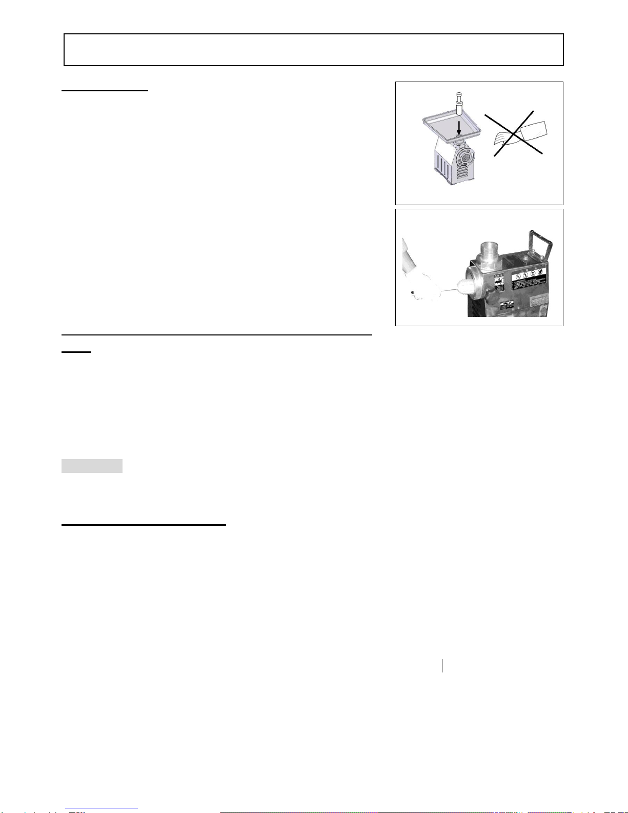
3. In particular, care should be taken to ensure that all the accessories are correctly fitted in position prior
to starting the machine. The machine is supplied factory lubricated and ready to run. The work surface
which the mincer is positioned must be a height of between approximately 90and 120cm; ensure that
the work surface is free of objects of any kind that may interfere with operation of mincer.
Model
UH-22MEC
Motor capacity
1.5 HP (1200W)
Voltage/ Frequency
220V / 50 / 60 HZ/3PH
380V / 50 / 60 HZ/3PH
Max. Current
220V / 6A
380 V / 2.8A
Speeds
176 RPM
Average hourly
production
230-250KG
Standard equipment
Pusher, Feed hopper,
5mm Extrusion plates,
Blade, Tube
Dimensions(mm)
455 x 321 x 530
Packed ( L* W * H )
510 x 370 x 560
Weight
35 KG (N .W)
38 KG (G .W)
SPECIFICATION

2
INSTALLATION
PACKAGE AND TRANSPORT
1. Care is needed in removing the appliance from its packing. It is recommended that at least two persons
lift the device.
2. After removing the appliance from its packing check, in particular, to see whether any damage has been
caused in transit. If in doubt, do not use the appliance and contact a specialist.
3. The material used to pack the device should not be thrown away but kept for future transport.
WARNING: Keep all parts of the said material such as boxes, packets, plastic bags etc. out of the
reach of children as they may be dangerous.
ELECTRICAL CONNECTION
CAUTION: The user should install an over-current
protection device (e.g. fuse or NFB) in the machine incoming
site power lines to prevent a fault current risk.
CAUTION: The machine is designed for TN power system.
Before connecting this mincer to the electrical supply, check
that the details on the rating plate (located on the side of the
mincer) correspond to the details of your electrical connection.
If the style of mincer’s plug is unsuitable for the socket you plan
to use, the plug must be cut off and replaced with an appropriate
plug. The mincer should be plugged into a switched socket which
isolates all poles to facilitate servicing. (Max.2 meters of cable). The mincer must be incorporated into a
potential equalization system.
The leakage current for this appliance is no greater than 1 ma/kw. If the electrical supply cable to the
machine becomes damaged, it must be replaced by a qualified electrician using cable which is H05-RNF
(Europe-CE), G14*1.25(USA-UL) or higher and suitable for a 1.5HP (0.55KW) motor load.
NOTE: The ground wire is fixed to the machine and this connection must be kept intact.
NOTE: Particular attention should be paid when switching on devices with three-phase electric
motors. The direction of operation of the mincer must be Anticlockwise. If the mincer operates in a
clockwise direction switch off the device and use the reverse direction of R.S.T. wires
The minimum requirement for all electrical equipment is correct operation between air temperature of
+5°C and +40°C.
Electrical equipment is capable of operating correctly when the relative humidity does not exceeding
95% at a maximum temperature of +40°C.
Electrical equipment is capable of operating correctly at altitude up to 1000m.
Electrical equipment is designed to withstand to protected against the effects of transportation, and
storage temperature within a range of –25°C to +55°C and for short periods not exceeding 24h at up to
+70°C.
(A)Rating Plate (B) Individual Plug

3
OPERATION
SAFETY TIPS
NEVER place your hand, tie, clothes, long hair or any kitchen
utensil in the outlet when the mincer is in operation. Isolate the
machine from the electrical supply by removing the plug from the
socket before cleaning or dismantling. A notice advising operator of
the safe use of this mincer is attached to the machine.
Please wearing apron for cleaning.
Please wear a glove to clean/remove blade.
No-frozen meat product is used.
The extrusion plate cannot be ground thinner the than 5mm
thickness
The mincer should be cleaned at the end of each work cycle.
For reasons of hygiene particular attention should be paid to
those parts which come into constant with the meat.
OFFICE, SHOPS AND RAILWAY PREMISES ACT,
1963
The above Act requires that this machine and attachments shall be operated only by a properly
instructed person or by an employee who is under the supervision of a properly instructed person. The
instruction shall include indication of the possible dangers arising and the precautions to be observed. The
act also requires that no person under the age of 18 shall clean a machine if this exposes him to risk of injury
from a moving part of that machine or any adjacent machine
WARNING: Do not allow children, unqualified persons who have not read this manual and are not
familiar with this mincer to use the appliance.
PARTICULAR WARNINGS
(1) This appliance must be used only for those purposes for which they were specifically designed. Any
other use is improper and therefore dangerous. The company cannot be considered responsible for any
damage resulting from improper wrong or unreasonable use.
(2) Do not allow children, unqualified persons who have not read this manual to use the appliance.
(3) Do not touch the moving parts when in operating. Be careful with hands, hair, tie, and clothing.
(4) Turn off the appliance and always unplug it before connecting the attachments and before cleaning.
(5) Before doing any cleaning, maintenance, replacing or when the device is not to be used in the long or
short term, please disconnecting the device from the mains electricity supply.
(6) Do not expose the machine to atmospheric agents such as rain, sunlight or any other agent which may
damage the internal parts in the long term, thus seriously reducing the degree of efficiency and safety.
(7) It is extremely important to avoid bringing the device into contact with water, solvents and harmful or
corrosive substances, for preventing the electrical shock. Never touch the machine with wet or damp
hands unless the device has been unplugged from the mains beforehand for preventing the electrical

4
OPERATION
shock. Take great care to avoid immersing the mincer in water or detergents,
particularly during cleaning operations, or using acid-based or inflammable
solutions which may damage the surfaces and affect the insulation of electrical
parts.
(8) Avoid pulling the cable to remove the plug from the socket, placing heavy
weights on the cable which may cause damage, or exposing it to sharp objects or
heat sources. To replace these or other electrical parts always contact qualified technicians.
(9) During mincing, the device does not operate correctly or emits unusual noises, switch the motor off
immediately and disconnect from the mains. Contact he local dealer or manufacturer to remedy the
problem.
(10) When carrying out repairs to the device, the damaged parts should be replaced exclusively with spare
parts supplied by the manufacturer. Always contact the local dealer or manufacturer when repairs are
required.
(11) Always switch off the device before leaving it, even for short lengths of time. Never operate the device
when it is empty. This will cause the extrusion plate and blade to heat up to a dangerous extent and may
lead to the seizure of the parts in contact.
(12) Do not introduce objects inside the motor ventilation casing or grating and mincing mouths.
(13) Do not introduce objects the beneath base of the appliance.
THERMAL OVERLOAD PROTECTION
The thermal overload protection will shut off and stop the machine automatically. If this occurs, please
turn off the mincer. After waiting few minutes, then turn on mincer.
TOOL INSTALLATION
WARNING: The blade and feed screw have very sharp edges and
parts. When mounting or dismantling these accessories handle with
extreme care to prevent injury EVEN WHEN THE MINCER IS
SWITCHED OFF. Injury may be caused by hands coming
accidentally into contact with the internal cutting edges of the mincer.

5
OPERATION
(1) Release the Screw (D) then insert the Outlet (E) to (C). Then tight the Screw (D) to its original
position.
(2) Now mount the Feed Screw (F) by inserting it in the Outlet (E).
(3) Insert the Blade (G) into the direction. Position the cutting edge of the blade towards the Extrusion
Plate (H) and insert into the Feed Screw Housing (E).
(4) Mount the Extrusion Plate (H) in the correct position with the hub towards the exterior. Finally screw
the Ring Nut (I) onto the threaded screw of the Outlet (E) and lock it without using excessive force.
(5) To position the Feed Hopper (B) correctly, line it up with the Opening (C) on the upper part of the
casing as shown.
WARNING: When mounting the ring nut on the outlet , do not over tighten as this may cause friction
between the moving parts, leading to increased wear, or cause the blade to become blunt prematurely.
WARNING: It is extremely dangerous to leave the accessories of the mincer such as the extrusion
plate, the blade or the feed screw within reach of children or unqualified persons.
CONTROLS
The UH –22MEC mincer is equipped with a single three-position
inverter.
(1) To switch on the mincer, press the Green Start Button (K). The
mincer should operate in Anticlockwise Direction.
(2) Switch off the mincer by pressing the Red Stop Button (L).
(3) Push the meat through the hole in the feed hopper using the Pusher.
If during mincing the feed screw should become blocked due to the
presence of thicker parts of meat (such as nerves) the direction of
operation should reversed for few seconds by pressing the Black
Reversed Button (M). Reset the correct direction of operation by
pressing the Start Button to continue mincing.
(1)
(2)
(3)
(4)
(5)

6
CLEANING
OPERATION
CORRECT USE OF THE MINCER
1. It is the responsibility of users to use the mincer correctly within the recommended limitations.
Always follow the instructions.
2. If the motor labors, stop the machine immediately.
3. Damage resulting from improper use is not covered by the SMAKY warranty. For additional
safety, the mincer will only start after the red stop button has been pressed to lock.
4. When first using, carefully wash the attachments in warm water or in dishwasher. (Material of the
attachments is 304# stainless steel.)
5. Choose the suitable working table.
6. Check the attachments, especially the blade and the extrusion plate, have been properly connected
before beginning the task.
7. Ensure that the extrusion plate is suitable for the type of mincing required. Never use a plate with holes
of over 8mm in diameter.
8. Insert the feed hopper. Place the appropriate container beneath the outlet to collect the minced meat.
9. Push the meat through the hole in the feed hopper using the pusher.
10. If during mincing the feed screw should become blocked due to the presence of bones of meat, the
direction of operation should reversed for few seconds by pressing the black reverse button.
Disconnect the device from the mains electricity supply when dismantling any part of the device.
Take out the bones and reset the correct direction of operation by pressing the start button to continue
mincing.
11. When work is complete always disconnect and clean the mincer.
WARNING: Always removing the plug from the socket before cleaning or dismantling.
WARNING: When cleaning the mincer, the moving parts must always be dismantled.
CLEANING
(1) The mincer should be cleaned at the end of each work cycle for reasons of hygiene, particular attention
should be paid to those parts which come into constant with the meat.
(2) Do not cleaning the mincer without disconnecting the device from the mains to prevent the electrical
shock and dangers.
(3) Do not cleaning the external casing with acid-based or base detergents or cleaning agents of any kind
which may damage the surface. Do not scour the surfaces with abrasive paper, abrasive pastes or steel
wool or clean with high pressure jets of water. Water jet cleaning is not allowed.
(4) Clean the external casing with a damp cloth or sponge, for greasy parts which are more difficult to clean
use a product designed for use with Aluminum Alloy material.
(5) Clean internal parts such as the inlet, pusher, feed hopper, outlet, feed screw, blade, ring nut and
extrusion plates (which come into direct contact with meat) with a damp sponge and washing up liquid
(neutral if possible). Do not clean with high pressure jets of water. Ensure that these parts are rinsed
and dried thoroughly.
WARNING : Isolate the mincer from the electrical supply by removing the plug from the socket
before cleaning or servicing

7
MAINTENANCE
GUARATEE
FAULT FINDING
MAINTENANCE
(1) Regular maintenance is necessary on all machines if they are to remain in good working order. It is
strongly recommended that this be carried out by trained technicians from a SMAKY appointed
distributor.
(2) To ensure that the mincer operates correctly, the blade must be sharpened at regular intervals.
Lubricate the machine and the gears.
ON AND ANNUAL BASIS
(1) Check that all bolts are tight and accessories are secured. Check the gear and the oil seal and replace if
necessary.
NOTE : We recommend that the above actions be carried out by a trained technician.
SMAKY guarantees that, for a period of 1 year from the date of dispatch from our factory or the date of
sale by one of our approved distributors, it will replace any parts that are defective as a result of faulty
design, material or workmanship, provided that no alteration, addition or repair has been carried out except
by an authorized Service Agent and provided that such defective part(s) be returned to the company’s nearest
authorized representative, postage paid.
FAULT
CHECK
POSSIBLE REASON AND ACTION REQUIRED
No power to
mincer.
Check plug socket.
Check wiring in plug.
Check fuse in plug.
Check or change cable.
Check plug switch.
Check IC Board.
Check fuse in IC Board.
Mincer not plugged into a live socket or not switched on.
Plug incorrectly wired - rewire correctly.
Possible faulty fuse - replace fuse.
Cable damaged or split - replace cable.
Switch damaged of faulty - replace switch.
IC Board damaged - replace IC Board.
Possible damaged fuse in IC Board - replace fuse.
Mincer
becomes noisy.
Check outlet, blade, feed screw,
ring nut, extrusion plates.
Check work surface.
Check bearing for ware.
Check gear box.
Ensure that accessories and tool are correctly seated.
Uneven surfaces create excessive resonance.
Worn bearings - replace bearings.
Damaged of faulty gear-replace gear.
Motor
overheating.
Check supply voltage.
Voltage should correspond to rating plate.
Oil on main
shaft.
Check oil seal.
Worn oil seal - change oil seal.

8
SCHEMATIC PARTS LIST

9
PARTS TABLE
ITEM
PARTS NO.
QTY.
DESCRIPTION
1
UH-2201
1
PLUG
2
UH-2202
1
PUSHER
3
UH-2203
1
FEED HOPPER
4
UH-2204
3
HEX SCREW (M5x30)
5
UH-2205
1
FEED HOPPER TUBE
6
UH-2206
1
OPENING TUBE
7
UH-2207
3
HEX SCREW (M5x30)
8
UH-2208
1
OUTLET FIXED PIN
9
UH-2209
1
OUTLET
10
UH-2210
1
STAINLESS PIN (Ø4x16)
11
UH-2211
1
FEED SCREW(SINGLE SIDE BLADE)
12
UH-2212
1
INSERT (SQUARE)
13
UH-2213
1
BLADE
14
UH-2214
1
EXTRUSION PLATE 6.2 mm (STANDARD)*
15
UH-2215
1
RING NUT
16
UH-2216
1
TUBE
17
UH-2217
2
RUBBER PLUG
18
UH-2218
1
FEED HOPPER ATTACHMENT
19
UH-2219
1
NUT (M8)
20
UH-2220
1
HEX SCREW (M10x15)
21
UH-2221
1
WASHER (M10x20)
22
UH-2222
2
WASHER (M8x16)
23
UH-2223
2
HEX SCREW (M8x15)
24
UH-2224
1
MAIN BODY
25
UH-2225
1
WARNING LABEL
26
UH-2226
1
DANGER LABEL
27
UH-2227
1
DATA PLATE
28
UH-2228
1
CONTROL PANEL
29
UH-2229
1
START BUTTON
30
UH-2230
1
STOP BUTTON
31
UH-2231
1
REVERSE BUTTON
Note: Please consult us first for different size EXTRUSION PLATES.

10
PARTS TABLE
ITEM
PARTS NO.
QTY.
DESCRIPTION
32
UH-2232
1
RUBBER PAD
33
UH-2233
1
SCREW (M12)
34
UH-2234
1
DANGER LABEL
35
UH-2235
1
ELECTRIC SHOCK WARING LABEL
36
UH-2236
2
SCREW (M5x12)
37
UH-2237
1
CAPACITOR ATTACHMENT
38
UH-2238
1
*CAPACITOR (FOR SINGLE PHASE USE ONLY)
39
UH-2239
1
BUSHING
40
UH-2240
1
BALL BEARING 6204zz
41
UH-2241
1
OIL SEAL (TC-47x30x10)
42
UH-2242
1
KEY WAY (5x5x15)
43
UH-2243
1
TRANSMISSION SHAFT
44
UH-2244
1
STRAIN RELIEVER PG 13.5
45
UH-2245
1
CORE
46
UH-2246
1
POWER PLUG (3 PH)
47
UH-2247
6
HEX SCREW (M6x20)
48
UH-2248
6
SPRING WASHER (M6)
49
UH-2249
1
GEAR REAR COVER
50
UH-2250
1
OIL SEAL PAD
51
UH-2251
2
PIN (Ø6x20)
52
UH-2252
1
BALL BEARING 6203
53
UH-2253
1
NUT (AN-D4)
54
UH-2254
1
WASHER (AN-D4)
55
UH-2255
1
TRANSMISSION GEAR 50HZ (58T)
UH-2255-1
1
TRANSMISSION GEAR 60HZ (57T)
56
UH-2256
1
BUSHING
57
UH-2257
1
BALL BEARING 6204Z
58
UH-2258
1
BAL BEARING 6203
59
UH-2259
1
KEY WAY (5x5x15)
60
UH-2260
1
TRANSMISSION SHAFT 50HZ (20T)
UH-2260-1
1
TRANSMISSION SHAFT 60HZ (17T)
61
UH-2261
1
TRANSMISSION GEAR 58T
62
UH-2262
1
BALL BEARING 6203

11
PARTS TABLE
ITEM
PARTS NO.
QTY.
DESCRIPTION
63
UH-2263
1
HEX SCREW (6x20)
64
UH-2264
1
WASHER (M6x25)
65
UH-2265
1
SPRING WASHER (M6)
66
UH-2266
1
MOTOR GEAR (20T)
67
UH-2267
1
OIL SEAL (28x20x6)
68
UH-2268
1
*CAPACITOR (FOR SINGLE PHASE USE ONLY)
69
UH-2269
1
MOTOR BODY
70
UH-2270
1
BALL BEARING 6024ZZ
71
UH-2271
1
MOTOR COIL
75
UH-2275
1
MOTOR SHAFT & CORE
72
UH-2272
1
KEY WAY (5x5x5)
73
UH-2273
4
SPRING WASHER (M5)
74
UH-2274
4
SCREW (M5x10)
76
UH-2276
1
BALL BEARING 6203ZZ
77
UH-2277
1
MOTOR REAR COVER
78
UH-2278
3
SCREW (M5x10)
79
UH-2279
1
PLANTINUM SWITCH (FOR SINGLE PHASE USE ONLY)
80
UH-2280
2
SCREW (M5x10)
81
UH-2281
1
SWIRL SWITCH (FOR SINGLE PHASE USE ONLY)
82
UH-2282
1
COOLING FAN
83
UH-2283
1
IC CONTROL PLUG & CORE
84
UH-2284
1
IC BOARD
85
UH-2285
4
SCREW (M3x6)
86
UH-2286
4
BRONZE PIN (M3x5)
87
UH-2287
1
ELECTRIC BOARD
88
UH-2288
4
SCREW (M5x14)
89
UH-2289
4
SPRING WASHER (M5)
90
UH-2290
1
BASE
91
UH-2291
4
BUTTOM RUBBER KNOBS
92
UH-2292
4
RUBBER WASHER (Ø8x16)
93
UH-2293
4
SUPPORT PIN (M8x20)
94
UH-2294
4
WASHER (M8x20)
95
UH-2295
4
NUT (M8)

12
PARTS TABLE
ITEM
PARTS NO.
QTY.
DESCRIPTION
96
UH-2296
1
OVERLOAD RELAY
97
UH-2297
1
OVERLOAD RELAY ATTACHMENT
UH-2297-1
1
TRACK
98
UH-2298
4
HEX SCREW (M5x12)
99
UH-2299
4
SPRING WASHER (M5)
Note: The specification of UH-2238 will be different subject to the voltage and
frequency. Please indicate the voltage and frequency when ordering.
Note: The specification of UH-2268 will be different subject to the voltage and
frequency. Please indicate the voltage and frequency when ordering.
OPTIONAL 1/2 UNGER (DOUBLE-CUT BLADE) ASSEMBLY
ITEM
PARTS NO.
QTY.
DESCRIPTION
100
UH-22100
1
OUTLET
101
UH-22101
1
STAINLESS PIN
102
UH-22102
1
FEED SCREW
103
UH-22103
1
INSERT (ROUND)
104
UH-22104
1
EXTRUSION PLATE (LARGE HOLES)
105
UH-22105
1
DOUBLE-CUT BLADE SET
106
UH-22106
1
EXTRUSION PLATE 4.5 mm (STANDARD)
107
UH-22107
3
BLADE (DOUBLE-CUT USE)
108
UH-22108
3
M5*0.8 SCREW
Table of contents