Perle S-10GR-STS User manual
Part# 5500434-10 (Rev G)
Perle S-10GR-STS
Media Converter
Installation Guide

Perle Standalone-S10-GR-STS-Installation Guide 2
Overview
This docu ent contains instructions necessary for
the installation and operation of the Perle
S10-GR-STS Standalone Media Converter. This
edia converter contains two pluggable
transceiver ports that per its insertion of two
SFP/SFP+. This edia converter can use either
Perle Syste s or third party MSA co patible
10G/2.5G/1G SFP+ odules. See the Technical
Specifications section in this guide for supported
odules.
Visit Perle’s web site for the ost up to date
Installation guides, odels and specifications.
http://www.perle.com/
Getting to know your
S-10GR-STS Media Converter
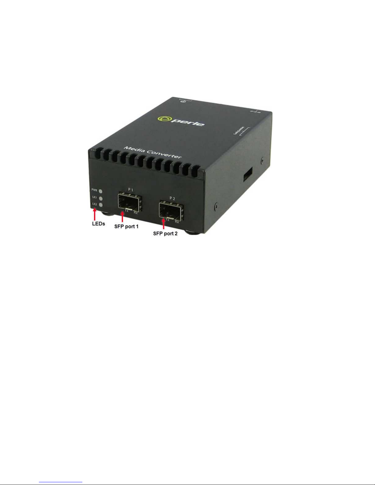
Your Perle S-10GR-STS Standalone Media
Converter package consists of the following ite s:
•S-10GR-STS with two SFP/SFP+ transceiver
ports
•Grounding screws
•Country specific power adapter
•Power cord strain relief clip
•Four rubber feet
•This guide
Perle Standalone-S10-GR-STS-Installation Guide 3
Front View

Perle Standalone-S10-GR-STS-Installation Guide 4
Installation
The default switch setting (all switches in the UP
position) will work for ost installations.
These are the steps required to configure the
S-10GR-STS edia converter.
1. Set the DIP switch settings. (optional).
2. Insert the appropriate SFP/SFP+ into the
transceiver ports.
3. Connect the fiber cables.
DIP Switches
Perle Standalone-S10-GR-STS-Installation Guide 5
DIP Switch Settings
The DIP switches are located on the side of the
unit.
Note: Switch changes ade when the unit is
powered up take effect i ediately and will result
in a link reset on both ports.
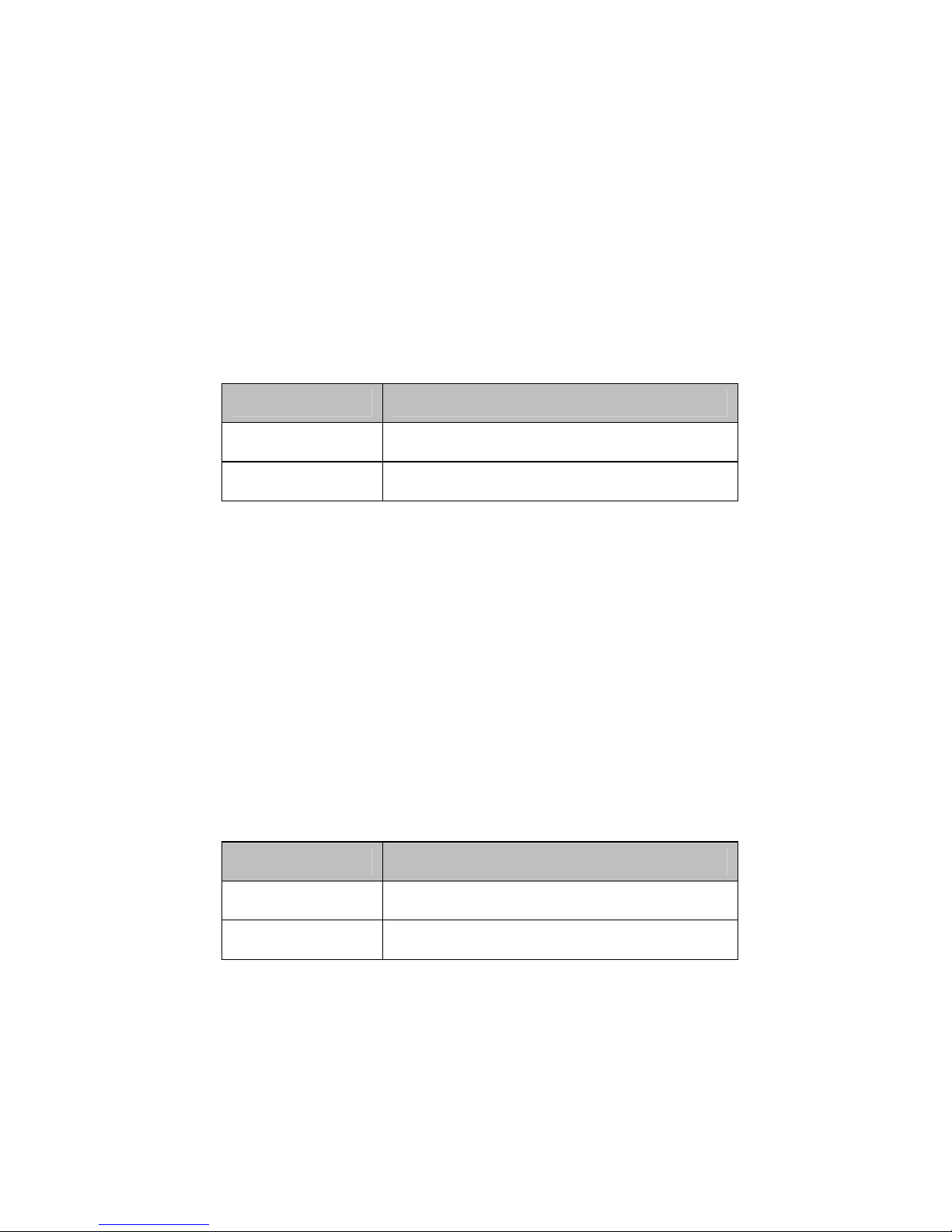
Link Mode (Switch 1)
Switch Position Mode
Up (default) Smart Link Pass-through
Down Standard
Smart Link Pass-through:
In this ode, the link
state on one port connection is directly reflected
through the edia converter to the other port
connection. If link is lost on one of the connections,
then the other link will be brought down by the
edia converter.
Standard:
In this ode, the links can be brought up
and down independently of each other. A loss of
link on either connection can occur without
affecting the other connection.
iber ault Alert (Switch 2)
Switch Position Mode
Up (default) Enabled
Down Disabled
Enabled: If the edia converter detects a loss of
signal on the fiber port, the edia converter
notifies the link partner on that sa e port that an
error condition exists by bringing down the link
.

Perle Standalone-S10-GR-STS-Installation Guide 6
Disabled: The edia converter will not onitor for
fiber fault.
Fiber Fault Alert Sample
Config
Media Converter A Configuration
•Link Mode – Standard Mode
•Fiber Fault Alert
Media Converter B Configuration
•Link Mode–S art Link Pass through Mode
•Fiber Fault Alert
Sequence of Events
1. Media Converter
A
loses fiber connection (RX).
2. Media Converter
A
notifies the re ote Media
Converter that there is a fault on the Link.
3. Media Converter
B
detects loss of fiber link on
receiver (RX).
4. Media Converter
B
turns off trans itter (TX).
Perle Standalone-S10-GR-STS-Installation Guide 7
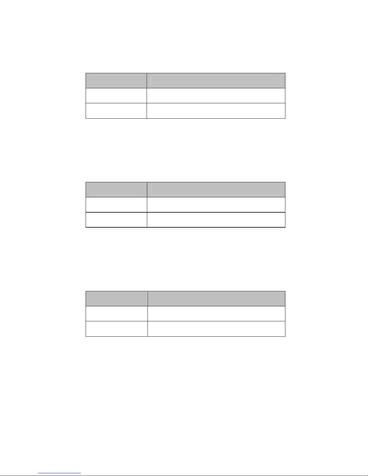
Cut-through / Rate converting (Switch 3)
Switch Position
Type
Up (default) Rate converting
Down Cut-through
Rate converting: Both ports can operate at the
sa e or different speeds.
Cut-through: Both ports need to be the sa e
speed and in full duplex ode.
iber Interface Lookback (Switch 4)
Switch Position Mode
Up (default) Disabled
Down Enabled
Enabled:
When enabled, the edia converter will
be in fiber loopback ode.
Disabled: When disabled, the edia converter will
not be in fiber loopback ode.
iber Loopback Interface (Switch 5)
Switch Position Mode
Up (default) Port 1
Down Port 2
UP: The edia converter will perfor loopback
testing on Port 1.
Down: The edia converter will perfor loopback
testing on Port 2.
Not Used (Switch 6 and 7)
Perle Standalone-S10-GR-STS-Installation Guide 8
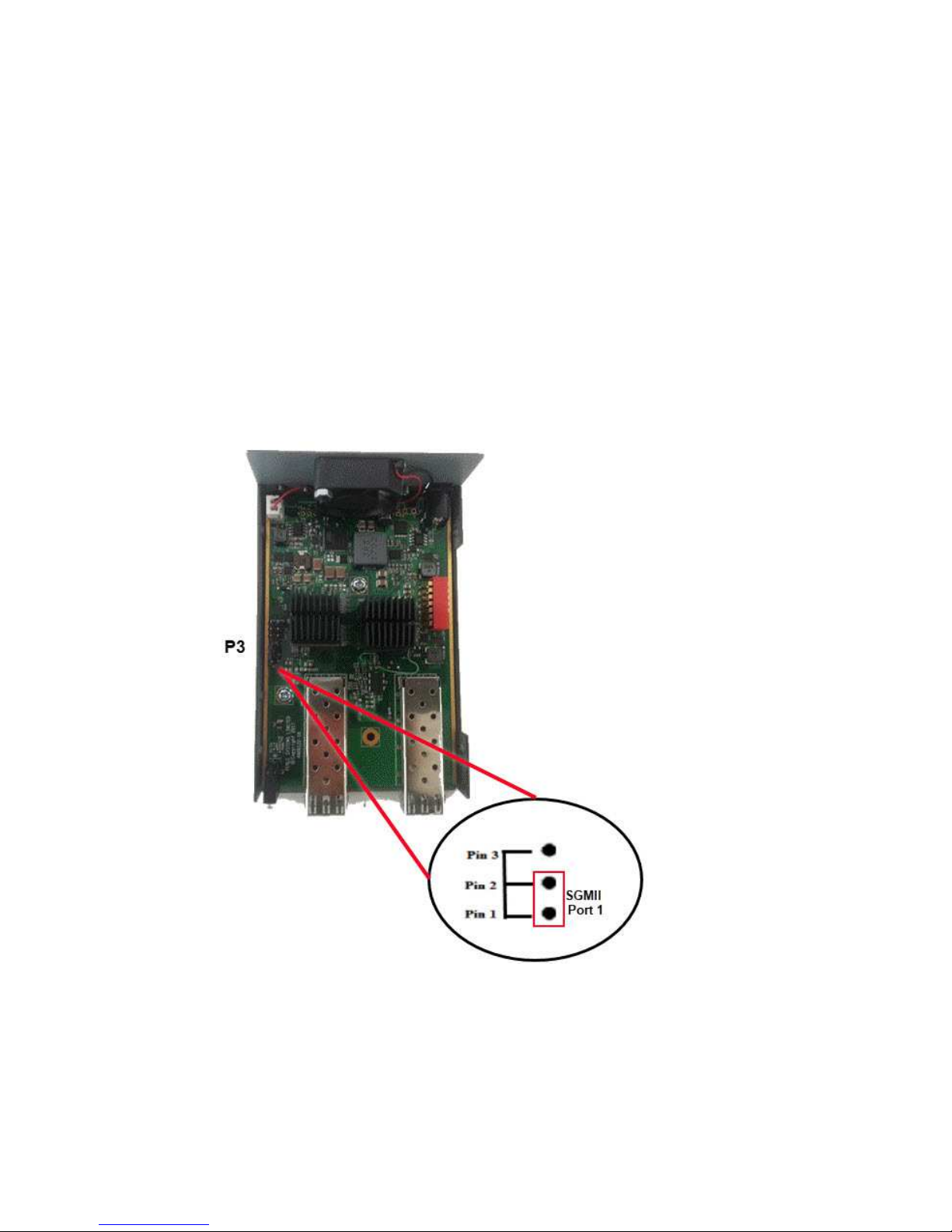
SGMII Interface Support
The Perle Standalone Media Converter has 1000
Mbps SGMII interface support on port 1.
To set the ju per, re ove the screws fro the
sides of the unit, then re ove the lid.
The SGMII ju per is located on the outer edge, at
the idpoint of the card (P3). Ju per Pin 1 and Pin
2 to select SGMII for port 1.
NOTE: Only port 1 supports SGMII.
Perle Standalone-S10-GR-STS-Installation Guide 9
Operation
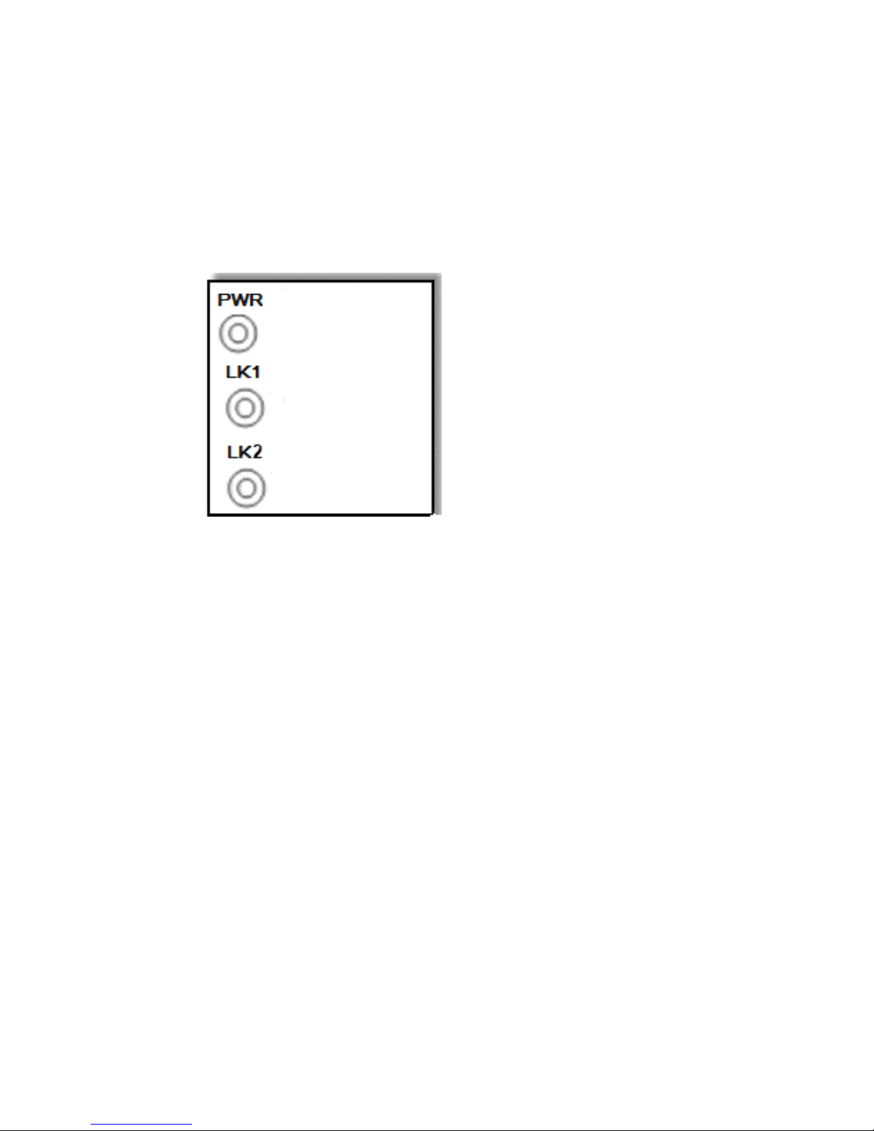
Status LED
The Perle S-10GR-STS edia converter LEDs
statuses.
PWR – Power/Test
Green On: Power is on and the odule is in nor al
operation ode.
Green blinking slowly: the odule is in test or
loopback ode.
Red Solid: During power up: Hardware error
detected. (See PWR Red LED Errors)
Red Blinking quickly: Error detected. (See LK1/LK2
Errors)
LK1 – Port 1 Activity
On: Fiber link present.
Blinking quickly: Fiber link present and receiving
data.
Blinking slowly: The fiber link has been taken down
as a result of S art Link Pass-through

Perle Standalone-S10-GR-STS-Installation Guide 10
Off: No fiber link present.
LK2 – Port 2 Activity
On: Fiber link present.
Blinking quickly: Fiber link present and receiving
data.
Blinking slowly: The fiber link has been taken down
as a result of S art Link Pass-through.
Off: No fiber link present.

Perle Standalone-S10-GR-STS-Installation Guide 11
LK1 / LK2 Error Codes
LK1
LK2
Meaning
Off Off Incompatible SFP/SFP+
On On Internal Error
Off On Mismatch in Cut-though mode
On Off SFP/SFP+ communication error
PWR-Red LED Errors
LK1 LK2 Meaning
Blinking Blinking
Blinking one second on, 3
seconds off: the maximum
specified operating
temperature within the
inserted module has been
exceeded
Off Off Internal Hardware.

Perle Standalone-S10-GR-STS-Installation Guide 12
Attaching the Grounding Lug
Grounding the Chassis If your installation requires
additional grounding follow this procedure.
Grounding the chassis requires the following ite s:
One grounding lug (not provided)
One 18-12 AWG wire (not provided)
Note: For your safety, when installing this
equip ent, always ensure that the chassis ground
connection is installed first and disconnected last
1. Attach the grounding lug to one end of an 18-
12 AWG wire.
2. Attach the grounding lug to the chassis and
secure with the grounding screw(s).
Perle Standalone-S10-GR-STS-Installation Guide 13
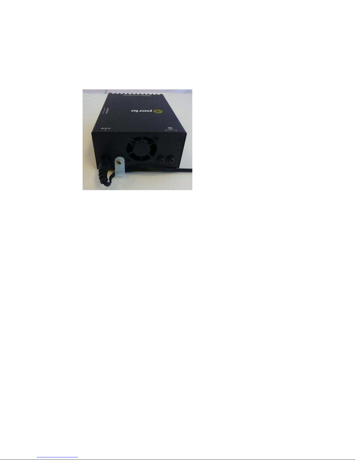
Attaching the Power Cord Strain
Relief Clip
1. Feed the power cord through the opening in
the power cord relief clip.
2. Attach the power cord relief clip to the chassis
and secure with the provided screw.
Perle Standalone-S10-GR-STS-Installation Guide 14
Installing the SFP Fiber Module
1. Locate appropriate fiber odules and insert
into the openings.
2. Ensure the SFP/SPF+ odules are properly
seated.
3. Proceed with fiber cable connections.
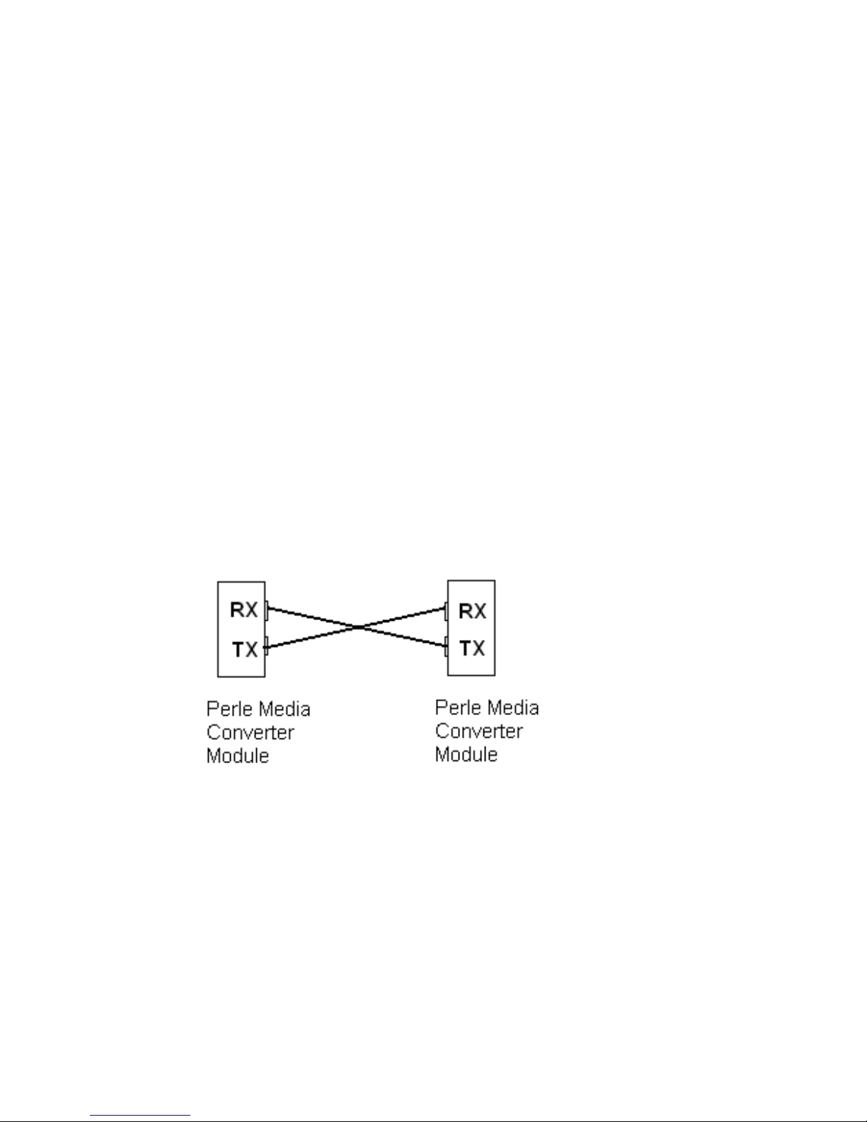
Installing the Duplex Fiber Cable
1. Locate a 1000/10GBase-X co pliant duplex (2
strands) fiber cable with appropriate
connectors.
2. Connect the fiber cables fro the SFP/SFP+ to
the other Media Converter/switch/fiber device
ensuring that the RX and TX are reversed
(crossed) at the opposite end.

Perle Standalone-S10-GR-STS-Installation Guide 15
Installing the Simplex Fiber
Cable
1. Locate 1000/10GBase-X co pliant si plex (1-
strand) fiber cables with appropriate
connectors.
2. Connect the fiber cables fro the SFP/SFP+ to
the other edia converter/switch/fiber device.
Temperature Protection
Every S-10GR-STS co es equipped with an internal
fan to provide cooling to the unit. The fan will
co e on during power up and then turn off. It will
only co e on when the te perature inside the
case beco es elevated. If the odule is operating
above its specified axi u operating
te perature, the S-10GR-STS will reduce the
power to the odule. The S-10GRT will continue to
onitor the operating te perature of the unit
until the te perature is below the axi u
operating te perature and then the S-10GT-STS
will return the odule to nor al operating.
Loopback Mode
The edia converter can be put into Loopback
ode for diagnosis purposes. A packet generator
and analyzer ust be used to generate and capture
the packets in this ode.
Perle Standalone-S10-GR-STS-Installation Guide 16
Technical Specifications
The following applies to the Perle S-10GR-STS
Media Converter.
Maximum power
consumption (watts) 18.2
Current Consumption
@ 12v 1.6 amps
Pluggable 10G Fiber
Transceivers Power levels 1 and 2
EEE 802.3ae (10G-Base-R)
10 Gigabit SFP+ slot support
10GBase-R
Standard SFP Power level 1 (1
watt) and level 2 (1.5 watts) as
per SFP-8431
Operating
Temperature: 0°C -50°C (32°F - 122°F)
Storage Temperature: -25°C -70°C (-13°F -158°F)
Operating Humidity: 5% to 90% non-condensing
Storage Humidity: 5% to 95% non-condensing
Operating Altitude: Up to 3,048 m (10,000 ft)
Weight: 0.36kg, 0.79 lbs

Perle Standalone-S10-GR-STS-Installation Guide 17
*Actual rating is dependent on the power
consu ption of the SFP/SFP+ odules inserted.
Supported 10 Gigabit iber pluggable
transceivers
IEEE 802.3as co pliant
•10GBase-SR
•10GBase-LMR
•10GBase-LR
•10GBase-ER
•10GBase-ZR
CWDM/DWDMBase
Supported 10 Gigabit Copper pluggable
transceivers
SFP+ Direct Attach Cable (DAC). Also, known as:
•Twinax
•10GBase-CU
•10GSFP+Cu
•10GBase-CX1
•10GBase-CR1
Note: Passive and Active cable types are supported
Supported Gigabit iber S P’s
•1000Base-SX
•1000Base-LX/LH
•1000Base-EX
•1000Base-ZX
•1000-Base-BX
•CWDM/DWDMBase
Note: In this ode both SFPs need to operate at
1000Base-X

Perle Standalone-S10-GR-STS-Installation Guide 18
iber Cabling Requirements
•MM: 50/125 icrons or 62.5/125 icrons
•SM 9/125 icrons
Note: Please refer the product page on the Perle
website for the ost up to date specifications.
http://www.perle.co /

Perle Standalone-S10-GR-STS-Installation Guide 19
Troubleshooting
General
Ensure that the SFP/SFP+ odules are inserted
correctly into the transceiver ports.
No connectivity
Set all DIP switches to the UP position.
Loopback Mode
The edia converter can be put into Loopback
ode for diagnosis purposes. A packet generator
and analyzer ust be used to generate and capture
the packets in this ode.

Perle Standalone-S10-GR-STS-Installation Guide 20
Co pliance Infor ation
FCC
This product has been found to comply with the limits for a Class A
digital device, pursuant to Part 15 of the FCC rules. These limits are
designed to provide reasonable protection against harmful interference
when the equipment is operated in a commercial environment. This
equipment generates, uses, and can radiate radio frequency energy
and, if not installed and used in accordance with the instructions in this
Guide, may cause harmful interference to radio communications.
Operation of this equipment in a residential area is likely to cause
harmful interference, in which case the user will be required to correct
the interference at his/her own expense.
EN 55032 Class A
WARNING
This is a Class A product. In a domestic environment, this
product may cause radio interference in which case the user may be
required to take adequate measures.
EN 55024 Class A
Contacting Technical Support
Contact information for the Perle Technical Assistance
Center (PTAC) can be found at the link below. A
Technical Support Query may be made via this web
page.
www.perle.com/support_services/support_request.shtml
Warranty / Registration
For infor ation and details about product warrantee and
registration, please refer to
http://www.perle.co /support_services/warranty.sht l
Copyright © 2017 Perle Syste s Li ited. All rights reserved.
No part of this docu ent ay be reproduced or used in any
for without written per ission fro Perle Syste s Li ited.
Table of contents
Other Perle Media Converter manuals

Perle
Perle S-1110P User manual

Perle
Perle S-10GRT-SFP User manual

Perle
Perle MCR1900 User manual

Perle
Perle C-10GT-SFP User manual

Perle
Perle CM-10G-STS User manual

Perle
Perle C-110-XXXXX User manual

Perle
Perle S-100-XXXXX User manual

Perle
Perle S-10GT-SFP User manual

Perle
Perle S-1110-M2xx05 User manual

Perle
Perle S-1110-XT 10 User manual

Perle
Perle S-10G-XTXH User manual

Perle
Perle C-100-XXXXX User manual

Perle
Perle C-1000MM-XXXXXX User manual

Perle
Perle MCR200 User manual

Perle
Perle C-1000MM Series User manual

Perle
Perle S-100MM-XXXXX User manual

Perle
Perle C-10GRT-SFP User manual

Perle
Perle S-110-P User manual

Perle
Perle MCR1900 User manual

Perle
Perle S-1000-SFP User manual


