smart home KeypadLinc INSTEON 2486D Series User manual
Page 1 of 24 Rev: 1/27/2012 5:26 PM
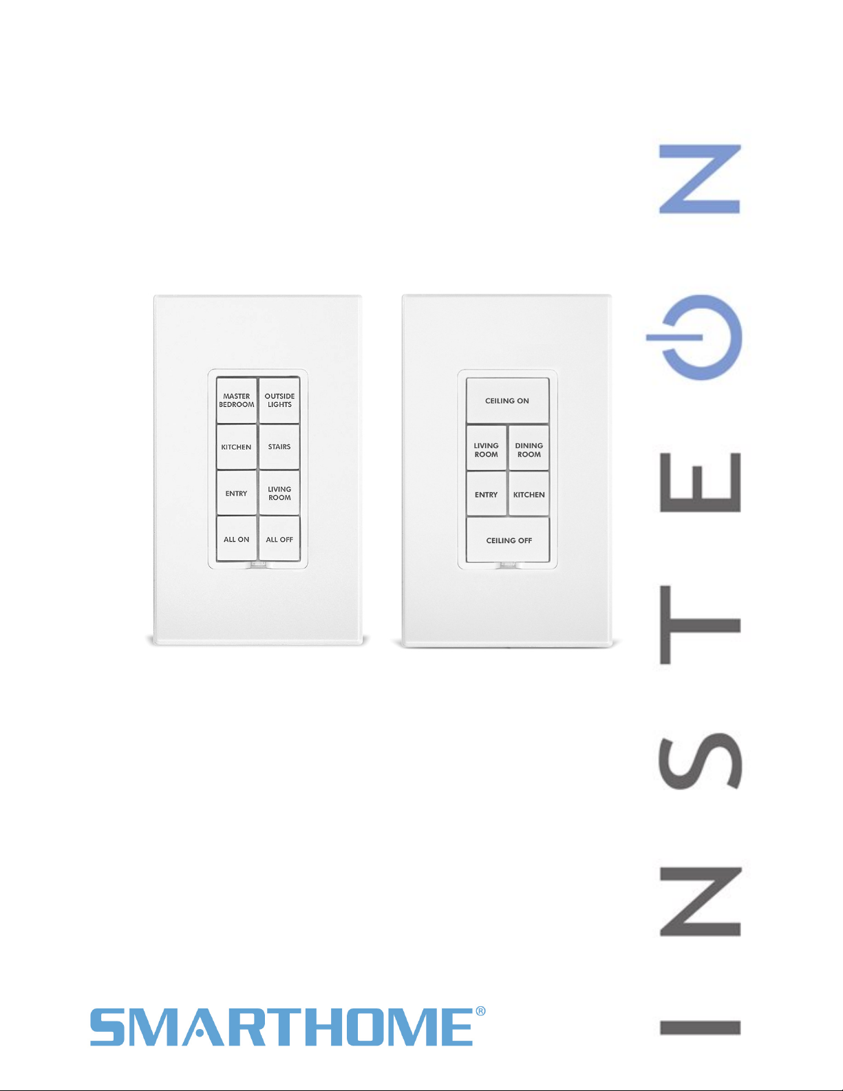
KeypadLinc™ Dimmer
INSTEON®6 and 8-Button Scene Control Keypad with Dimmer
Owners Manual, Rev 5.0+
(#2486Dxxx)
Shown above with optional custom etching and screwless wallplates (sold separately)
8-button KeypadLinc 6-button KeypadLinc

KeypadLinc – Features & Benefits............................................................................................................ 3
Features .................................................................................................................................................... 3
What’s in the box? ..................................................................................................................................... 3
Installing KeypadLinc ................................................................................................................................. 4
Identifying the Electrical Wires in your Home............................................................................................ 4
Tools Needed ............................................................................................................................................ 4
Button Naming........................................................................................................................................... 4
Installation – Circuit with 1 Switch ............................................................................................................. 5
Installation – Circuit with 2 Switches ......................................................................................................... 6
Installation – Circuit with 3 (or more) Switches ......................................................................................... 7
Using KeypadLinc....................................................................................................................................... 9
LEDs.......................................................................................................................................................... 9
Button Taps ............................................................................................................................................... 9
Button Tap / Press & Holds ....................................................................................................................... 9
Local On-Level .......................................................................................................................................... 9
Setting Up INSTEON Scenes ................................................................................................................... 10
Add KeypadLinc Button to a Scene as a Controller ................................................................................10
Remove KeypadLinc Button from a Scene as a Controller..................................................................... 10
Add KeypadLinc Button to a Scene as a Responder .............................................................................. 11
Remove KeypadLinc from a Scene as a Responder .............................................................................. 11
Changing Button Modes (Toggle / Non-Toggle Mode) ........................................................................... 11
LED Brightness........................................................................................................................................ 12
Power Restore......................................................................................................................................... 12
Add X10 Address to a Button .................................................................................................................. 12
Remove X10 Address from a Button....................................................................................................... 12
Advanced X10 Programming .................................................................................................................. 12
Advanced Features ................................................................................................................................... 13
Add Multiple Scene Responders (formerly “Multi-Linking Mode”)........................................................... 13
Remove Multiple Scene Responders (formerly “Multi-Unlinking Mode”) ................................................ 13
Synchronized Scenes (formerly “Cross-Linking”).................................................................................... 13
Beep on Button Tap or Press .................................................................................................................. 14
“Radio” Button Groups (only 1 LED of “N” at a time – software recommended)..................................... 15
Air Gap..................................................................................................................................................... 16
Factory Reset .......................................................................................................................................... 16
Changing Between 6 and 8 Button Configurations .................................................................................17
Changing to 6-Button Configuration .................................................................................................... 17
Changing to 8-Button Configuration .................................................................................................... 17
Changing Buttons .................................................................................................................................... 18
Local-Ramp-Rate (software recommended) ........................................................................................... 18
Additional Resources ............................................................................................................................... 18
Helpful Videos ......................................................................................................................................... 18
Optional Accessories............................................................................................................................... 19
Specifications............................................................................................................................................ 19
Troubleshooting........................................................................................................................................ 21
Certification and Warranty ....................................................................................................................... 24
Certification.............................................................................................................................................. 24
FCC & Industry Canada Compliance Statement.....................................................................................24
ETL / UL Warning (Safety Warning)........................................................................................................ 24
Limited Warranty ..................................................................................................................................... 24
Limitations............................................................................................................................................ 24
Page 2 of 24 Rev: 1/27/2012 5:26 PM
KeypadLinc – Features & Benefits
Congratulations on the purchase of the elegant and high quality KeypadLinc. It is a Scene Controller (of
up to 8 INSTEON / X10 Scenes) plus has a built in dimmer. Additionally, each button has an LED which is
easily configured as a status indicator for virtually any INSTEON device/Scene you wish to monitor.
Features
- Easy to setup and use
- Integrated dimmer (up to 600 watts), 32 dim levels, 32 ramp rates
- Each button can be a Scene Controller and/or a Scene Responder
- Each button can control the other buttons on the keypad
- Supports up to 417 Scene memberships
- Multiple buttons can be included in the same Scene
- Each button can be configured to:
- Toggle between sending Ons and Offs (default)
- Always send an On
- Always send an Off
- Dimmable, status LEDs
- Beeper
- Makes setup a breeze
- Can function as a chime module
- Configurable to beep on each button tap or press
- X10 Compatible
- Wires in like standard wall switch (requires a Neutral)
- All settings preserved through power failures
- Local programming lockout available via software
- 2-year warranty
- Custom etched buttons available
- Can be converted between 6 and 8 button modes
What’s in the box?
- KeypadLinc Dimmer
- Quick-Start Guide
- 2 mounting screws
- 4 wire nuts
Page 3 of 24 Rev: 1/27/2012 5:26 PM

Installing KeypadLinc
CAUTIONS AND WARNINGS
Read and understand these instructions before installing and retain them for future reference.
This product is intended for installation in accordance with the National Electric Code and local regulations in the United States or
the Canadian Electrical Code and local regulations in Canada. Use indoors only. This product is not designed or approved for
use on power lines other than 120V 60Hz, single phase. Attempting to use this product on non-approved power lines may have
hazardous consequences.
Recommended installation practices:
- Use only indoors or in outdoor rated box
- Be sure that you have turned off the circuit breaker or removed the fuse for the circuit you are installing this product into.
Installing this product with the power on will expose you to dangerous voltages.
- Connect using only copper or copper-clad wire
- This product may feel warm during operation. The amount of heat generated is within approved limits and poses no
hazards. To minimize heat buildup, ensure the area surrounding the rear of this product is as clear of clutter as possible.
- Each INSTEON product is assigned a unique INSTEON ID, which is printed on the product’s label.
- To reduce the risk of overheating and possible damage to other equipment, do not use this product to control Loads in
excess of the specified maximum(s) or, install in locations with electricity specifications which are outside of the product’s
specifications. If this device supports dimming, please note that dimming an inductive Load, such as a fan or transformer,
could cause damage to the dimmer, the load bearing device, or both. If the manufacturer of the load device does not
recommend dimming, use a non-dimming INSTEON on/off switch. USER ASSUMES ALL RISKS ASSOCIATED WITH
DIMMING AN INDUCTIVE LOAD.
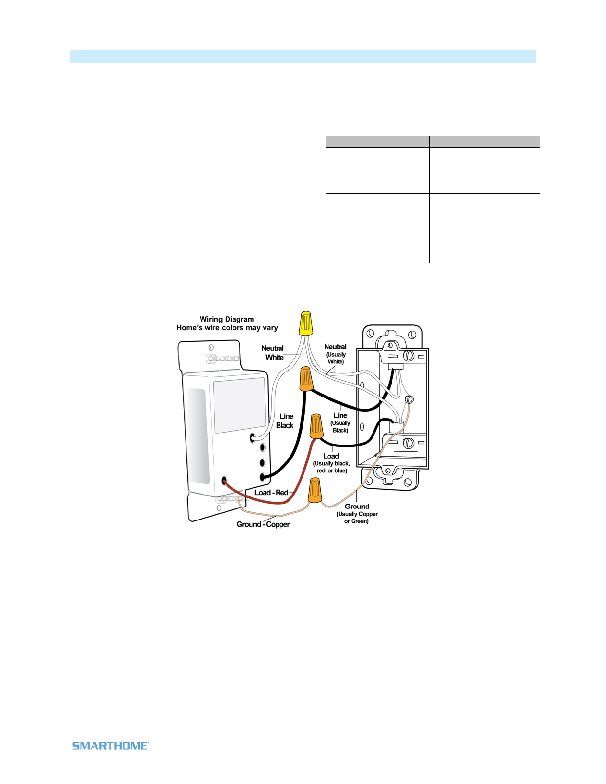
Identifying the Electrical Wires in your Home
- Line - usually Black, may also be called HOT, LIVE or Power, carries 120VAC electricity into the wall box
- Neutral - usually White commonly daisy chained from box to box usually appearing as a White wire bundle
- Load – usually Black from a separate cable jacket
- Ground - Bare wire or metal fixture (if grounded)
IMPORTANT!
If you have any difficulties or questions, consult an electrician. If you are not knowledgeable about, and comfortable with
electrical circuitry, you should have a qualified electrician install the product for you.
Tools Needed
Slotted screwdriver •Phillips screwdriver
Wire cutter / stripper •Voltage Meter
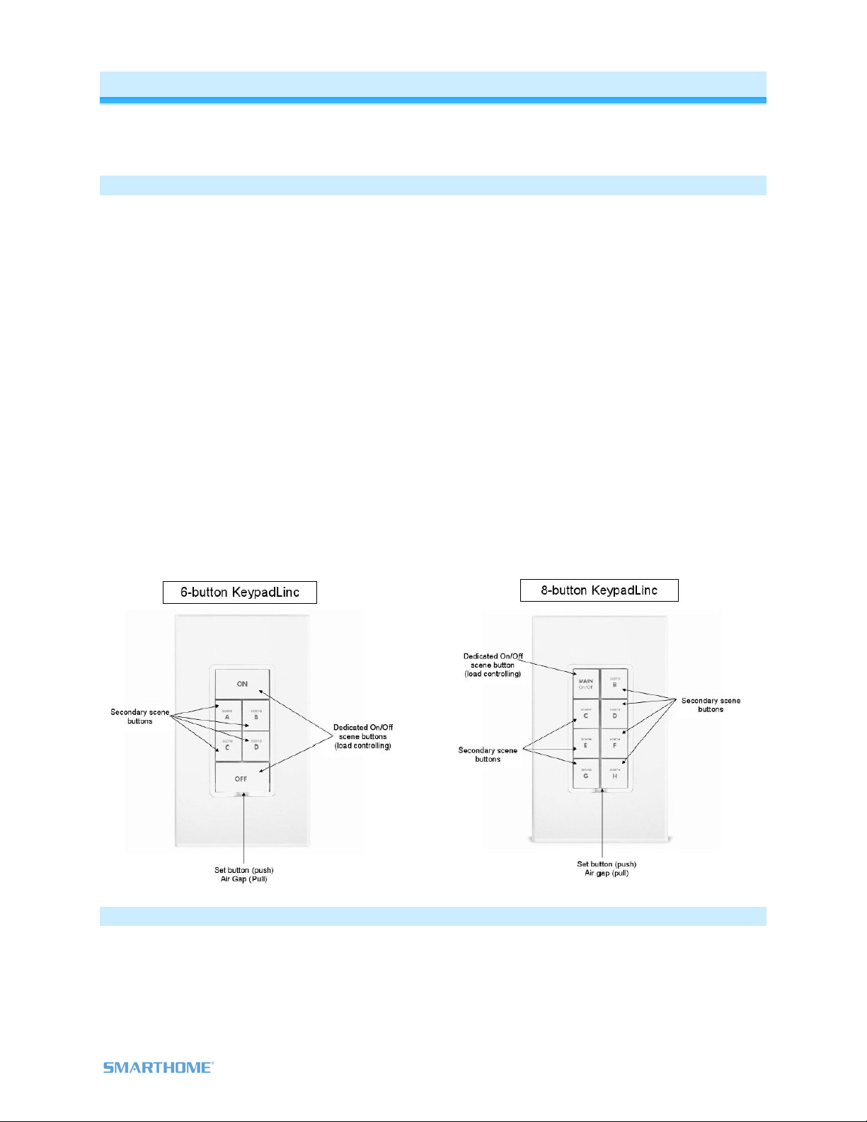
Button Naming
Throughout this manual, we will use the following naming conventions:
Page 4 of 24 Rev: 1/27/2012 5:26 PM
Page 5 of 24 Rev: 1/27/2012 5:26 PM
Installation – Circuit with 1 Switch
1) At electrical panel, turn off circuit breaker(s) and/or remove fuse(s) feeding wall box (verify that the
power is off)
2) Remove wallplate from the switch and unscrew switch you are replacing and gently pull out
3) Disconnect wires from switch1
4) Turn power back on
5) Use a voltage meter to identify Line and Load
wires which connected to the switch
6) Identify Neutral and Ground wires
7) Turn power off
8) Connect wires as per table/diagram (confirm firm
attachment with no exposed wire)
9) With button labels right-side up, gently place
KeypadLinc into wall box and screw into place
10) Turn power back on
KeypadLinc’s On button and connected
light will turn on
11) Verify KeypadLinc is working properly by tapping
On and Off on a 6-button KeypadLinc or MAIN On
and Off on a 8-button KeypadLinc turning connected light on and off
12) Reinstall the wallplate
1If the wires cannot be detached by unscrewing them, cut the wires where they enter the switch, then strip ½” of insulation off the ends
KeypadLinc Wire Wall Box Wires
Bare Copper
Ground
(commonly bare,
Green wire or Green
screw)
White Neutral
(commonly White)
Red Load
(Light, Fan, etc.)
Black Line
(120V to Ground)

Installation – Circuit with 2 Switches
Circuits with 2 switches are called 3-way circuits. Both switches in a 3-way circuit need to be replaced by
KeypadLincs (and/or SwitchLincs).
Note: 3-way circuits require a pair of wires called Travelers between joining wall boxes to operate.
INSTEON switches, dimmers and keypads do not require both Traveler wires for 3-way circuits to
function. Simply wire one to Line, Neutral and Load; the other(s) to Line and Neutral. Use one Traveler to
share Line between boxes. Adding to a Scene creates a virtual 3-way circuit.
1) Turn off circuit breaker(s) and/or remove fuse(s) feeding wall boxes (verify that power is off)
2) Pull both switches from their wall boxes, each existing 3-way switch will have no less than 3 wires
3) Remove wires from existing switches
4) Make sure wires are safely separated from each other and turn power back on
5) Using a voltage meter measure each wire to Ground in both boxes until you find the single wire
supplying 120V (Line)
a. We will now refer to that location as box 1
b. The other box will have the Load wire. That will be box 2
6) Turn power back off
In Box 1 (Line box)
7) Connect bare Ground wire from
the KeypadLinc to bare Ground
wire or Ground screw in wall box
8) Connect White Neutral wire from
KeypadLinc to Neutral wire(s) in
wall box (usually White)
9) Using a wire nut, cap Red wire
from KeypadLinc
10) Connect Black wire from
KeypadLinc to 120V Line wire in
wall box (usually Black) along with
one Traveler wire running between
boxes (preferably Black). Note
color of Traveler you are using as
this will carry Line voltage to box 2
11) Cap unused Traveler
In Box 2 (Load box)
12) Connect bare Ground wire from
KeypadLinc to bare Ground
wire or Ground screw in wall
box
13) Connect White Neutral wire
from KeypadLinc to Neutral
wire(s) in wall box (usually
White)
14) Connect Red wire from
KeypadLinc to Load wire
15) Connect Black wire from
KeypadLinc to same color
Traveler from box 1 carrying
Line (usually Black)
16) Cap unused Traveler wire
Page 6 of 24 Rev: 1/27/2012 5:26 PM

17) With button labels right-side up, gently place KeypadLincs into wall boxes and screw in place
18) Turn power back on
KeypadLinc’s On button and connected light will turn on
Only KeypadLinc in box 2 will operate the Load until you synchronize Scenes to the 2
devices
19) Add both KeypadLincs to a Scene as a Controller and Responder of each other (see
Synchronized Scenes)
20) Verify both KeypadLincs are working properly by tapping On and Off on a 6 button KeypadLinc or
MAIN On and Off on an 8 button KeypadLinc turning connected light on and off
21) Reinstall wallplates
Installation – Circuit with 3 (or more) Switches
Circuits with 3 or more switches are called 3-way/4-way circuits. All switches in 3-way/4-way circuits need
to be replaced by KeypadLincs (and/or SwitchLincs).
Note: 3-way/4-way circuits require a pair of wires called Travelers between joining wall boxes to operate.
INSTEON switches, dimmers and keypads do not require both Traveler wires for 3-way/4-way circuits to
function. Simply wire one to Line, Neutral and Load; the other(s) to Line and Neutral. Use one Traveler to
share Line between boxes. Adding to a Scene creates a virtual 3-way/4-way circuit. The following
example shows three switches.
1) Turn off circuit breaker(s) and/or remove fuse(s) feeding wall boxes (verify that power is off)
2) Pull all three switches from their wall boxes, each existing 3-way switch will have a minimum 3
wires; 4-way switches will have 4 wires
3) Remove wires from existing switches
4) Make sure wires are safely separated from each other and turn power back on
5) Using a voltage meter measure each wire to Ground in all three boxes until you find the single
wire supplying 120V (Line)
a. We will now refer to that location as box 1
b. The location having 2 sets of matching pairs of wires will be box 2 (i.e. 2 Reds and 2
Blacks, or other matching colors). These are 2 Travelers from box 1 and 2 Travelers
leading to box 3.
c. The last box will have the Load wire, that will be box 3
6) Turn power back off
In Box 1 (Line box)
7) Connect bare Ground wire from
KeypadLinc to bare Ground wire or
Ground screw in wall box
8) Connect White Neutral wire from
KeypadLinc to Neutral wire(s) in
wall box (usually White)
9) Cap Red wire from KeypadLinc
10) Connect Black wire from
KeypadLinc to 120V Line wire in
wall box (usually Black) along with
one Traveler wire running between
boxes (preferably Black). Note
color of Traveler you are using as
this will carry Line voltage to box 2
11) Cap unused Traveler wire
Page 7 of 24 Rev: 1/27/2012 5:26 PM

Page 8 of 24 Rev: 1/27/2012 5:26 PM
In Box 2 (Traveler box)
12) Connect bare Ground wire from
KeypadLinc to bare Ground wire or
Ground screw in wall box
13) Connect White Neutral wire from
KeypadLinc to Neutral wire(s) in
wall box (usually White)1
14) Cap Red wire from KeypadLinc
15) Connect Black wire from
KeypadLinc to same color Traveler
from box 1 that you connected to
Line along with same color
Traveler wires leading to box 3
16) Cap the last unused Traveler
wire(s)
In Box 3 (Load box)
17) Connect bare Ground wire from
KeypadLinc to bare Ground wire
or Ground screw in wall box
18) Connect White Neutral wire from
KeypadLinc to Neutral wires(s)
in wall box (usually White)
19) Connect Red wire from
KeypadLinc to Load wire
(usually Black)
20) Connect Black wire from
KeypadLinc to Line Traveler
from box 2 (Line Traveled from
box 1 through 2 into 3 usually
Black)
21) Cap unused Traveler wire
22) With button labels right-side up,
gently place KeypadLincs into
wall boxes and screw in place
23) Turn power back On
KeypadLinc’s On button and connected light will turn on
Only KeypadLinc in box 3 will operate the load until you synchronize Scenes on the 3
devices
24) Add each KeypadLincs to a Scene as a Controller and Responder of each other (see
Synchronized Scenes)
22) Verify all KeypadLincs are working properly by tapping On and Off on a 6 button KeypadLinc or
MAIN On and Off on an 8 button KeypadLinc turning connected light on and off
25) Reinstall wallplates
1If Neutral is not available in this box; use other unused Traveler from box 1 to carry Neutral to box 2. Label and mark any differently colored wire being connected to Neutral
with a piece of white tape to flag it as Neutral.
Using KeypadLinc
LEDs
LED Meaning
Brighter On
Dim Off
Button Taps
Button Type Button LED State
before Tap Effect of Tap Effect of Double-tap
Toggle Off Turn Scene
Members On Turn Scene Members On Instantly
Toggle On Turn Scene
Members Off Turn Scene Members Off Instantly
Always On Either Turn Scene
Members On Turn Scene Members On Instantly
Always Off Either Turn Scene
Members Off Turn Scene Members Off Instantly
Notes:
1) The connected light(s) will react just like Scene Responders to button taps of MAIN (when using an
8-button KeypadLinc) and On or Off (when using a 6-button KeypadLinc)
2) LED will mimic the on/off status of a dimmer whose Scene level is 100% bright
3) ON button on a 6 button KeypadLinc is an “Always On” button while OFF button is an “Always Off”
button. Other buttons are toggle by default.
Button Tap / Press & Holds
Button Type Button LED
before Tap
Effect of First
Press & Hold Effect of Subsequent Press & Holds
Toggle Off Brighten Scene until
release
Opposite of last Press & Hold
(e.g. if last was brightening, it will dim)
Toggle On Dim Scene until
release
Opposite of last Press & Hold
(e.g. if last was brightening, it will dim)
Always On Either Brighten Scene until release
Always Off Either Dim Scene until release
Local On-Level
The Local On-Level is the brightness that the light(s) physically wired to KeypadLinc will come on at when
turned on locally. The default is 100%.
Local On-Level can be set to any one of 33 settings
32 fixed brightness levels (3% to 100%)
Or “Resume Bright”
• Previous brightness level is stored when turned off and recalled to that level
brightness when turned back on
Page 9 of 24 Rev: 1/27/2012 5:26 PM

Page 10 of 24 Rev: 1/27/2012 5:26 PM
To set KeypadLinc’s Local-On-Level:
1. Press & hold On and/or Off (or Main in 8-button configuration) until the connected light is at the
brightness desired when turned on locally (turn the light off if you wish to use the “Resume Bright”
feature)
2. Tap KeypadLinc’s Set button
KeypadLinc will (Beep)
3. Test the Local On-Level settings by tapping the On/Off or Main
Setting Up INSTEON Scenes
INSTEON remote control is done using Scenes. Scenes allow you to instantly “recall” favorite lighting
and appliance settings at the touch of a button (or in response to central control or even a sensor). Each
Scene has at least one Controller and at least one Responder. Simple Scenes can be setup using the
instructions below. Software is recommended for setup of larger scenes.
Add KeypadLinc Button to a Scene as a Controller
Follow the steps below to control a Scene (one or more INSTEON devices) from a KeypadLinc button.
1) Tap KeypadLinc button of choice (use button labeled “ON” when using a 6 button Keypads as “main”
Scene)
2) Press & hold KeypadLinc’s Set button until KeypadLinc beeps
KeypadLinc’s Scene button LED will blink
3) Adjust Scene Responder to the “state” you want when Scene is activated from KeypadLinc (e.g.,
50%, 25% or even OFF)1
4) Press & hold Responder’s Set button until it double-beeps (or until its LED/Load flashes)
KeypadLinc will (Beep)-(Beep) and its LED will stop blinking 2
Responder’s LED will stop blinking and it may (Beep)-(Beep) 2
5) Confirm that Scene addition was successful by tapping on/off on the KeypadLinc Scene button
The Responder will toggle between the Scene’s on level and off
6) If you wish to add more Responders to the Scene, repeat steps 1-5 for each additional Scene
Responder (or see Add Multiple Responders to a Scene)
Remove KeypadLinc Button from a Scene as a Controller
If you want to remove KeypadLinc from a Scene(s) as a Controller follow instructions below. Whenever
possible, use software such as HouseLinc for managing Scene memberships.
Note: If you choose to remove KeypadLinc from use, it is important that you remove Scene memberships
from all Responders. Otherwise, delays and error blinks / reports may result. Follow the instructions below
for each Responder that KeypadLinc is a member of.
1) Tap KeypadLinc Scene button (ON for 6 button main Scene)
The Responder(s) will respond
2) Press & hold KeypadLinc’s Set button until it beeps
KeypadLinc’s Scene button LED will blink
3) Press & hold KeypadLinc’s Set button until it beeps again
KeypadLinc’s Scene button LED will continue blinking
4) Press & hold Responder’s Set button until it double-beeps (or LED blinks)
KeypadLinc will (Beep)-(Beep) and its Scene button LED will stop blinking
5) Confirm that Scene removal was successful by tapping Scene button on and off
Responder will not respond
1If the Responder is a multi-Scene device such as a KeypadLinc, tap the Scene button you wish to control until its LED is in the desired Scene state (on or off)
2If either the KeypadLinc or Responders LED continues to blink, the addition failed. Tap the device’s Set button until LED stops blinking and try again.

Page 11 of 24 Rev: 1/27/2012 5:26 PM
6) If you wish to remove multiple Responders from KeypadLinc, repeat steps 1-5 for each additional
Responder (or see Remove Multiple Responders from a Scene)
Add KeypadLinc Button to a Scene as a Responder
1) Press & hold the Scene Controller button until it beeps1
Controller’s LED will blink
2) Tap KeypadLinc button you wish to be a Responder of the Scene at least once
3) Tap button again if necessary to get button’s LED to desired state for Scene (press & hold if adding
the main Scene at a dimmed level)
4) Press & hold KeypadLinc’s Set button until it double-beeps
KeypadLinc’s Scene button LED will flash once & return to previous state
Controller’s LED will stop blinking and it will (Beep)-(Beep)2
5) Confirm that Scene addition was successful by tapping on then off on the Controller’s Scene button
KeypadLinc button LED will toggle between On and Off (+Load if main Scene)
Remove KeypadLinc from a Scene as a Responder
If you want to remove KeypadLinc from a Scene(s) as a Responder follow instructions below. Whenever
possible, use software such as HouseLinc for managing Scene memberships.
Note: If you choose to remove KeypadLinc from use, it is important that you remove Scene memberships
from all Controllers. Otherwise, Controllers will retry commands repetitively, creating network delays.
Follow the instructions below for each Scene Controller that KeypadLinc is a member of.
1) Press & hold Controller’s Scene button until Controller beeps3
Controller’s LED will blink
2) Press & hold the Scene button until Controller beeps again3
Controller’s LED will continue blinking
3) Tap KeypadLinc button to remove from Scene
4) Press & hold Set button on KeypadLinc until it double-beeps
KeypadLinc’s LED will flash once
Controller’s LED stops blinking
5) Confirm Scene removal was successful by tapping the button on the Controller with Scene you just
removed
KeypadLinc will no longer respond
Changing Button Modes (Toggle / Non-Toggle Mode)
You can change any button to any one of 3 Button Modes (software is recommended):
Toggle – toggles between ON and OFF commands each time it is tapped
Always Off – sends ON every time it is tapped
Always On – sends OFF every time it is tapped
Note: You cannot change the dedicated On and Off buttons when in 6 button configuration
1) Tap the button you want to change
2) Press & hold KeypadLinc’s Set button until it beeps
The button’s LED will begin blinking
All illuminated LEDs on KeypadLinc will brighten to 100%
3) Press & hold KeypadLinc’s Set button a 2nd time until it beeps a 2nd time
The button’s LED will continue blinking
4) Press & hold KeypadLinc’s Set button a 3rd time until it beeps a 3rd time
The button’s LED will stop blinking
1If the Controller does not have a beeper, wait until its LED begins blinking
2Most models
3For devices without beepers hold until its LED begins blinking (this may take 10+ seconds)

The button rotates to the next Button Mode in the cycle:
Toggle
Always Off
Always Off
Always On
Always On
Toggle
5) Tap the button several times to confirm it is now in the desired state
a. If you wish to rotate button mode again, return to step 2
LED Brightness
KeypadLinc’s LEDs can be set to any one of 32 brightness levels.
6-Button Configuration
1) Simultaneously tap the A and D buttons
KeypadLinc will beep
2) Use the On (brighter) and Off (dimmer) buttons to adjust LED brightness
3) When you have reached desired brightness, simultaneously tap the A and D buttons again
KeypadLinc will beep
Back to ready mode
8-Button Configuration
1) Simultaneously tap the C and F buttons
KeypadLinc will beep
2) Press & hold On button to adjust the LED brightness. (Each press & hold will toggle between brightening
and dimming)
3) When you have reached desired brightness, simultaneously tap the C and F buttons
KeypadLinc will beep
Power Restore
KeypadLinc stores all of its Scenes, properties, etc. in non-volatile memory. As such, all settings are retained
after a power outage. Upon power being restored, KeypadLinc will return its connected load and all LEDs to
their states prior to power outage.
Add X10 Address to a Button
1) Tap the KeypadLinc button
2) Press & hold KeypadLinc’s Set button until it beeps
The button’s LED will begin blinking
3) Send the desired X10 Address, plus ON, 3 times (e.g. send B5, BON, B5, BON, B5, BON)
KeypadLinc will double-beep and the button’s LED will stop blinking
Remove X10 Address from a Button
If you are no longer going to utilize an X10 address associated with KeypadLinc, it is very important that
you remove its X10 address. Otherwise, KeypadLinc will still listen for X10 commands (somewhat
hindering INSTEON reception) and may respond to spurious X10 “noise” which is unavoidable.
Furthermore, KeypadLinc will transmit an X10 address and command every time the button is tapped.
1) Tap KeypadLinc button
2) Press & hold KeypadLinc’s Set button until it beeps
Button’s LED will blink
3) Press & hold KeypadLinc’s Set button again until it beeps again
button’s LED will continue blinking
4) Send the X10 Address, plus ON, 3 times (e.g. send B5, BON, B5, BON, B5, BON)
KeypadLinc will double-beep and button’s LED will stop blinking
Advanced X10 Programming
Instructions on setting X10 primary address and Scene addresses can be found online:
http://www.smarthome.com/insteon-x10-programming.html
Page 12 of 24 Rev: 1/27/2012 5:26 PM

Advanced Features
Add Multiple Scene Responders (formerly “Multi-Linking Mode”)
1) Tap Scene Controller button on KeypadLinc
2) Press & hold KeypadLinc’s Set Button until it beeps
KeypadLinc’s Scene button LED will blink
All illuminated LEDs on KeypadLinc will brighten to 100%
3) Tap KeypadLinc’s Set Button
KeypadLinc’s Scene button LED will continue blinking
4) For each Responder you are adding
a. Adjust Responder to desired Scene state (for KeypadLincs you must tap the button at
least once – until in desired state)
b. Press & hold Responder’s Set button until it beeps (or LED flashes)
KeypadLinc will (Beep)
5) After all Responders have been added, tap KeypadLinc’s Set Button
KeypadLinc’s Scene button LED will stop blinking
KeypadLinc’s LEDs will return to normal brightness
6) Test Scene by tapping Scene button a couple of times
All the Responders added above will respond
Remove Multiple Scene Responders (formerly “Multi-Unlinking Mode”)
1) Tap Scene Controller button on KeypadLinc
2) Press & hold KeypadLinc’s Set Button until it beeps
KeypadLinc’s Scene button LED will blink
All illuminated LEDs on KeypadLinc will brighten to 100%
3) Press & hold KeypadLinc’s Set Button again until it beeps again
KeypadLinc’s Scene button LED will continue blinking
4) Tap KeypadLinc’s Set Button
KeypadLinc’s Scene button LED will continue blinking
5) For each Responder you are removing
a. If a KeypadLinc button, tap button
b. Press & hold Responder’s Set button until it beeps (or LED flashes)
6) After all Responders have been removed, Tap KeypadLinc’s Set Button
KeypadLinc’s Scene button’s LED will stop blinking
KeypadLinc’s LEDs will return to normal brightness
7) Test Scene by tapping Scene button a couple of times
All the Responders removed will not respond
Synchronized Scenes (formerly “Cross-Linking”)
Synchronized Scenes are Scenes where all members stay synchronized. Common examples include 3-
way lighting circuits and Scenes with a single Load bearing device. For our example we will Synchronize
Scenes on 2 SwitchLincs and identify them as A and B.
Example: 2 Switch Circuit
1) Turn both switches/dimmers on – to the desired (and same) Scene level
2) Press & hold Switch A’s Set button until it beeps (or LED blinks)
Switch A’s LED will blink
3) Press & hold Switch B’s Set button until it double-beeps (or LED flashes)
Switch B will (Beep)-(Beep) and its LED will flash once
Switch A will (Beep)-(Beep) and its LED will stop blinking
4) Press & hold Switch B’s Set button until it beeps (or LED blinks)
Switch B’s LED will blink
5) Press & hold Switch A’s Set button until it double-beeps (or LED flashes)
Switch A will (Beep)-(Beep) and its LED will flash once
Page 13 of 24 Rev: 1/27/2012 5:26 PM

Switch B will (Beep)-(Beep) and its LED will stop blinking
6) Test the group by controlling the Load from Switch A and then Switch B
The Load, Switch A’s status LED(s) and Switch B’s status LED(s) will all remain in synch
Example: Synchronized Scene with numerous members
Software is recommended, however, the following steps, when carefully followed, will also work. For our
example we will Synchronize SwitchLincs 1 through “N” (where N = any number).
1) Turn all switches on – to the desired (and same) Scene level
a. Press & hold Switch 1’s Set button until it beeps (or LED blinks)
Switch 1’s LED will blink
b. Tap Switch 1’s Set button
Switch 1’s LED will continue blinking (it is now the Scene Controller)
c. For Switches 2 through N, press & hold the Set button on each, one at a time, until it double-
beeps (or LED flashes)
Switch 2 through N will (Beep)-(Beep) and its LED will flash once
d. Tap Switch 1’s Set button
Switches 2 through N are now Responders and Synchronized to Switch 1
2) Return to Step 1 above, systematically placing each of the remaining switches (2-N) into this step as
the Scene Controller and all others as Responders of the Scene
All switches 1 – N are now synchronized as Scene Controllers and Scene Responders of all group members
Beep on Button Tap or Press
Buttons can be set to Beep Mode so KeypadLinc will beep every time a button is used. (Default = Off)
If KeypadLinc in 6-Button Configuration
Simultaneously tap the B and C buttons
KeypadLinc will beep
Keypad’s Beeper will toggle to on (if was off) or off (if it was on)
If KeypadLinc in 8-Button Configuration
Simultaneously tap the D and E buttons
KeypadLinc will beep
Keypad’s Beeper will toggle to on (if was off) or off (if it was on)
Page 14 of 24 Rev: 1/27/2012 5:26 PM
Page 15 of 24 Rev: 1/27/2012 5:26 PM
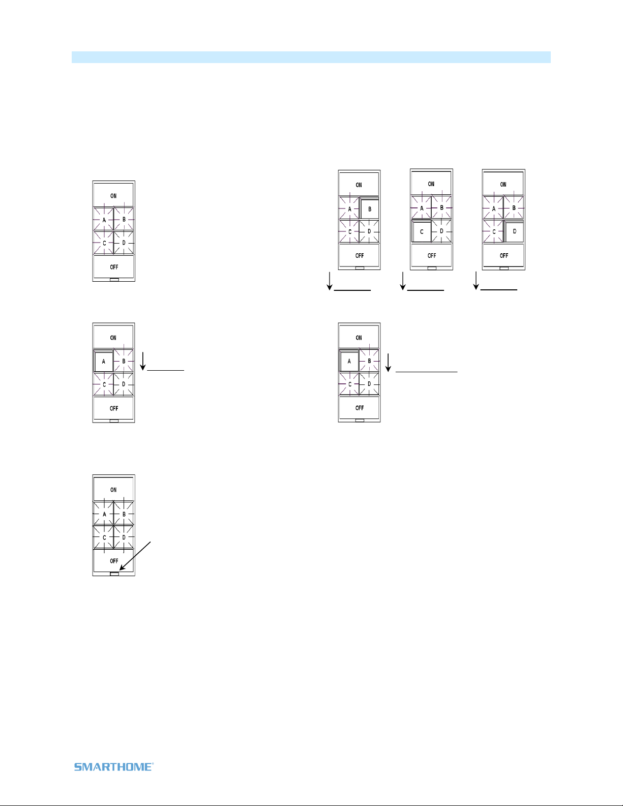
“Radio” Button Groups (only 1 LED of “N” at a time – software recommended)
This feature is especially handy if you have multiple Scenes controlling the same devices, such as Lights-
Bright, Lights Medium and Lights Off. When you tap any of the Scene buttons, the “others” LEDs will turn
off (as if they were Scene Responders), perfect for Scene change indication. This is a two-part
programming sequence as follows:
Part 1 Radio Button Groups
1) Tap each radio group button one at a time
each LED is on. In this example we will group
the four small buttons on 6-button KeypadLinc.
2) Press & hold button A until it beeps (about 10
seconds)
3) Tap the Set button (this places the unit in Add
Multiple Responders mode)
4) Press & hold, one at a time, buttons B, C and
D until each beeps
5) Tap the button you started with in step 1 to
end this programming step
6) Repeat steps 1-5, inserting button B into step
2 and all other buttons into step 4
7) Repeat steps 1-5, inserting button C into step
2 and all other buttons into step 4
8) Repeat steps 1-5, inserting button D into step
2 and all other buttons into step 4
9) After ending the last program step, verify
you’re “Radio” Button Groups by tapping each
button in the group. Each tap should turn On
that specific button in the group and
immediately turn Off any others in the group
presently On.
~10 sec Beep
~10 sec Beep
~10 sec Beep
~10 sec Beep Press & release

Page 16 of 24 Rev: 1/27/2012 5:26 PM
Part 2 Radio Button Groups
1) Tap each radio group button until its LED is Off
2) Press & hold button A until it beeps (about 10
seconds)
3) Tap the Set button (this places the unit in Add
Multiple Responders mode)
4) Press & hold, one at a time, buttons B, C and
D until each beeps
5) Tap the button you started with in step 1 to
end this programming step
6) Repeat steps 1-5 inserting button B into step 2
and all other buttons into step 4
7) Repeat steps 1-5 inserting button C into step 2
and all other buttons into step 4
8) Repeat steps 1-5 inserting button D into step 2
and all other buttons into step 4
9) After ending the last program step, verify your
“Radio” Button Groups by tapping each button
in the group. Each tap should turn On that
specific button in the group and immediately
turn Off any others in the group presently On.
Air Gap
To remove all power from KeypadLinc and connected light(s), pull the Set button at the bottom of the
switch out as far as it will go, about 1/8”. (It might be helpful to use a small screwdriver.) This will open
mechanical contacts creating an Air Gap.
To restore power, tap the air gap back into place, until its top is even with the trim frame.
Factory Reset
Factory Reset clears all user settings from KeypadLinc including INSTEON Scenes, On-Levels, Ramp
Rates, X10 addresses, etc.
1) Pull Set button out (creating an Air Gap)
2) Wait 10 Seconds
3) Push Set Button in and Hold it in
KeypadLinc will (Beep)
~10 sec Beep
~10 sec Beep
~10 sec Beep
Press & release
~10 sec Beep

4) Release the Set button
Device’s embedded software will re-write all settings to factory defaults
A couple of seconds will pass
KeypadLinc will (Beep)-(Beep)
LEDs will return to normal brightness
KeypadLinc returns to Ready Mode
Connected load will turn on
Changing Between 6 and 8 Button Configurations
Changing to 6-Button Configuration
1) Replace the 8-button plate with the 6-button plate - Attach the change-out plate to the switch
body by aligning the tabs and snapping into place
2) Gently pull the Set button out as far as it will go
3) Wait 10 seconds
4) While simultaneously holding the On and Off buttons, carefully push the Set button back in, flush
with the trim frame
5) Once the Set button is pushed in, continue holding the On and Off buttons for 3 seconds, and
then release
KeypadLinc will (Beep)
KeypadLinc is now in 6 Button Mode
Changing to 8-Button Configuration
1) Replace the 6-button plate with the 8-button plate - Attach the change-out plate to the switch
body by aligning the tabs and snapping into place
2) Gently pull the Set button out as far as it will go
3) Wait 10 seconds
4) While simultaneously holding the On/Off (upper left-most) button and the H button, carefully press
the Set button back in flush with the trim frame
5) Once the Set button is pushed in, continue holding the On/Off button and H buttons for 3
seconds, and then release
KeypadLinc will (Beep)
KeypadLinc is now in 8 Button Mode
Page 17 of 24 Rev: 1/27/2012 5:26 PM

Changing Buttons
KeypadLinc buttons can be changed to customize its appearance. Use
care when removing the keycaps. Using a small, flat-edged screwdriver
(ONLY) pry up on the sides of the keys from the middle of the keypad
(when possible). Make sure you are centered on the key as to catch the
small edge located there for this purpose.
Also, please note that behind the buttons are clear plastic filler pieces
which diffuse the LED’s light more elegantly. Use care to keep these filler pieces in the button frame as
you re-assemble. Should any damage occur to KeypadLinc during customization, please contact 800-
762-7845 and we will be happy to replace your frame.
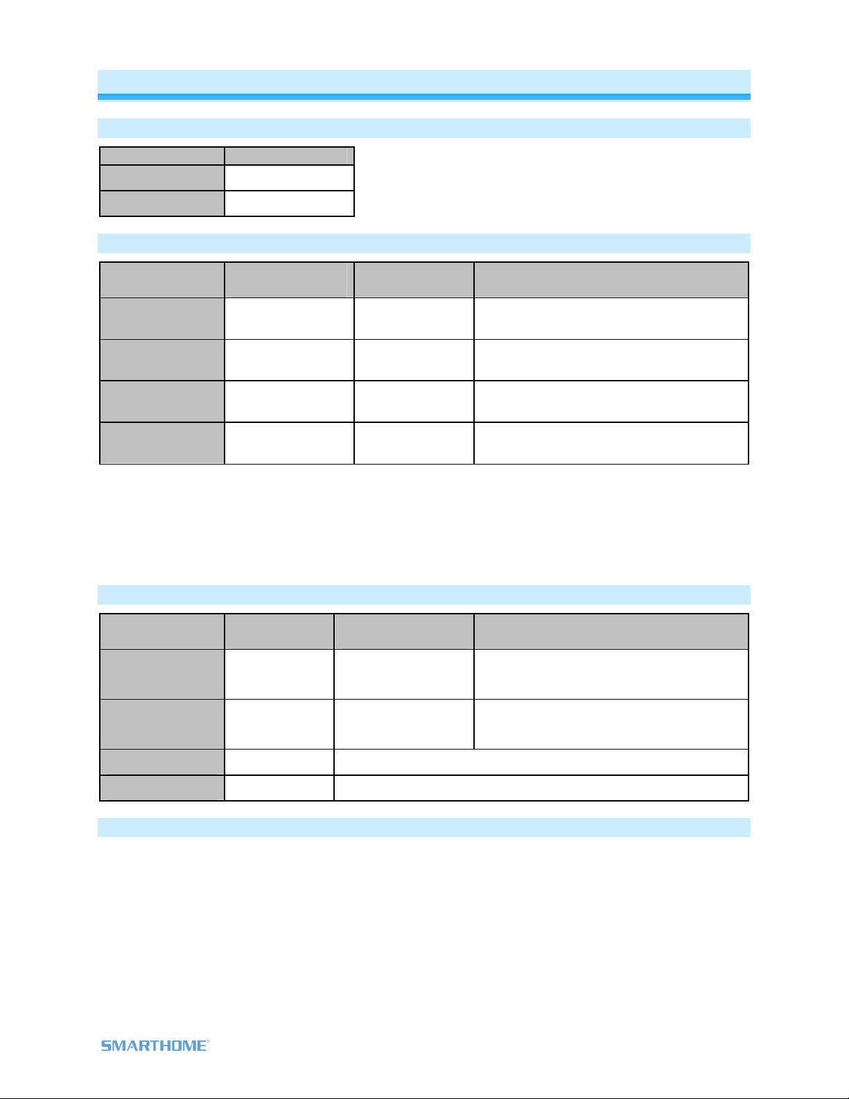
Local-Ramp-Rate (software recommended)
The Local-Ramp-Rate is the time it takes for the light(s) physically wired to KeypadLinc to brighten from
Off to 100% brightness. The default is 0.5 seconds. Local-Ramp-Rate is adjustable from 0.1 seconds to 8
minutes (0.1- 9 seconds using the instructions below or up to 8 minutes using software such as
HouseLinc)
1) Adjust the connected light(s) to brightness corresponding to desired Ramp-Rate
Brightness Level Ramp Rate in Seconds
90-100% 0.1
77-87% 0.2
65-74% 0.3
52-61% 2.0
39-48% 2.0
26-35% 4.5
13-23% 6.5
1-10% 8.5
1% 9.0
2) Double-tap the Set button on your KeypadLinc
KeypadLinc will (Beep)-(Beep)
3) Test the Ramp Rate settings by tapping the On/Off buttons on your KeypadLinc or Controller
Connected light(s) will ramp up and down at the new rate
4) Start again if the ramp rate is not as desired or, if your double tap was not fast enough you may
have accidentally changed the Local-On-Level instead of the Local-Ramp-Rate (note: software
allows you to set on levels and ramp rates exactly as desired and consistently around the house)
Additional Resources
Find home automation solutions, helpful tips, interactive demos, videos, user forums, and more at the
Smarthome Learning Center: www.smarthome.com/learningcenter.html
Helpful Videos
- Changing KeypadLinc Buttons
- Adding LED Diffusers to the KeypadLinc
Page 18 of 24 Rev: 1/27/2012 5:26 PM

Optional Accessories
Accessories Link
Custom Etched & Pre-
Printed Buttons
http://www.smarthome.com/_/ProductResults.aspx?Ntt=custom%20etch
ed%20buttons
Color & 6/8 Button Change
Kits (15)
http://www.smarthome.com/_/ProductResults.aspx?Ntt=keypadlinc%20
button%20change%20kit
Blank Buttons http://www.smarthome.com/2401BT10/Blank-10-Button-Set-for-
KeypadLinc-White/p.aspx
Clear Buttons http://www.smarthome.com/2401CLB/6-or-8-Button-Change-Kit-for-
KeypadLinc-Clear/p.aspx
LED Color Change Kit http://www.smarthome.com/2401L/LED-Color-Change-Kit-for-
KeypadLinc-4-Color/p.aspx
Table Top Stand Kit http://www.smarthome.com/_/KeypadLinc/KeypadLinc_Tabletop_Contro
ller/_/2vj/2wX/nav.aspx
Specifications
General
Product Name KeypadLinc Dimmer - INSTEON 6/8 Button Scene Control
Keypad with Dimmer
Brand Smarthome
Manufacturer Product Number 2486D
UPC
6 button
White - 2486DWH6: 689076407847
Almond - 2486DAL6: 718122387311
Light Almond - 2486DLAL6: 813922011586
Black - 2486DBK6: 718122387519
Gray - 2486DGY6: 718122387915
Ivory - 2486DIV6: 718122388110
Brown - 2486DBR6: 718122387717
8 button
White - 2486DWH8: 689076409049
Almond - 2486DAL8: 718122387410
Light Almond - 2486DLAL8: 813922011593
Black - 2486DBK8: 718122387618
Gray - 2486DGY8: 718122388011
Ivory - 2486DIV8: 718122388219
Brown - 2486DBR8: 718122387816
Patent Number 7,345,998 US, International Patents Pending
Warranty 2 Years, Limited
INSTEON
INSTEON Models available as 6 and 8 button Controller Scenes &
6 and 8 button Responder Scenes
Maximum Scene Memberships 400
Page 19 of 24 Rev: 1/27/2012 5:26 PM

Brightness Levels 32 (256 with software)
Local On Level Adjustable, 32 levels plus Resume Dim
Local Ramp Rate Adjustable, 0.1 seconds to 8 seconds locally, 0.1 seconds to 9
minutes via software
On Off
Fast On Fast Off
Scene Commands Supported as
Controller
Press & Hold Bright Press & Hold Dim
On Off
Fast On Fast Off
Incremental Bright Incremental Dim
Scene Commands Supported as
Responder
Press & Hold Bright Press & Hold Dim
Software Configurable Yes, Always
RF Range 150’ Open air
X10 Support Yes
X10 Addresses 256 max, unassigned by default
INSTEON Device Category 0x01 Dimmable Lighting Control
2486Dxx8 0x1C
INSTEON Device Subcategory 2486Dxx6 0x1B
Mechanical
Mounting Standard, single gang wall box
Wires 4, 16 gauge
Black - Line
White - Neutral
Red - Load
Wires
Bare - Ground
Case Color Clear
Set Button 1
Plastic UV Stabilized Polycarbonate
Beeper Yes
LED 8, White
Dimensions 4.1" H x 1.8" W x 1.2" D
Weight 3.6 oz
Operating Environment Indoors
Operating Temperature Range 32-104 F
Operating Humidity Range 0-85% Relative Humidity
Electrical
Voltage 120VAC +/- 10%
Frequency 60Hz
Maximum Dimmer Load 600 Watts in a single gang box
Page 20 of 24 Rev: 1/27/2012 5:26 PM
This manual suits for next models
27
Table of contents
Other smart home Lighting Equipment manuals

Popular Lighting Equipment manuals by other brands


GAME OF BRICKS
GAME OF BRICKS Thor's Hammer 76209 instruction manual
EuroLite
EuroLite LED Pixel Panel 16 DMX user manual

Endless Pools
Endless Pools FastLane owner's manual

CoeLux
CoeLux 45 HC P Series user manual

thomann
thomann stairville dj lase performance 150 RGY user manual

LDR
LDR Samba A100 CM operating instructions

Clevertronics
Clevertronics L10 Cleverfit Pro Installation & maintenance instructions

Compass
Compass CSWEU2LED quick start guide

Adam Hall
Adam Hall 87451SMART manual

Lumen Dynamics Group
Lumen Dynamics Group OmniCure S2000 user guide

EuroLite
EuroLite RGB FLOOD-1500 DMX MK2 user manual

ADJ
ADJ SWEEPER BEAM QUAD LED User instructions