Smart Witness CP4-NA-LTE User manual

R
CP4-NA-LTE
4 Channel HD Recorder
Installation Guide
smartwitness.com
Version 1.2

Warning: 3
Introduction: 4
Recording 4
Playback and Analysis 4
Package Contents: 5
Hardware Overview: 6
Dimensions 6
Rear View 7
Installation 7
Accessory Camera Types 8
Restrictions 9
Acceptable Congurations 9
Unacceptable Congurations 10
GPS Reception: 11
Power Cable and Wiring: 12
Power Connection 12
Video Output Cable & I/O Harness 12
Locking Enclosure: 13
Front View (open) 13
Rear View (closed) 13
Wi Modem Connection: 13
LCD Monitor Connection: 14
Completion & Power-up: 15
Troubleshooting: 16
LED Status: 17
CP4-NA-LTE -Table of Contents

smartwitness.com | 1016 Lunt Ave. Schaumburg, Illinois U.S.A. | Tel: 312.981.8774 | sales.usa@smartwitness.com
3
THIS IS VIDEO TELEMATICS
CP4
4 Channel HD Recorder
Installation Guide
MODEL: CP4-NA-LTE
Version: 1.2
Warning
SmartWitness installations should be performed by a qualied individual or
installation professional only. Working with a vehicle’s power system can be
dangerous to both you and your vehicle. This installation is intended only to be a
guide since vehicle designs and power/input sources can vary signicantly from
vehicle to vehicle.
If you need to schedule a professional installation service in the USA for your
SmartWitness device(s), please visit smartwitness.com/scheduleinstall and submit
the online form.
All cellular-enabled CP4 devices must use the installation wizard for proper
onboarding and activation, please visit install.smartwitness.com to register, login,
and use the SmartInstall wizard.

smartwitness.com | 1016 Lunt Ave. Schaumburg, Illinois U.S.A. | Tel: 312.981.8774 | sales.usa@smartwitness.com
4R
Introduction
The SmartWitness CP4 is the world’s smallest 4 channel LTE-enabled vehicle recorder. CP4 is small,
lightweight, easy to use, and simple to install. CP4 can be easily installed inside a glove box or
purchased with a locking case to prevent unauthorized access to the recorded data. An LCD monitor
is not required for use, but can be added to provide added visibility in and around the vehicle for
added security and safer operation.
Features
Recording
• 720P recording on channels 1-3 D1 (720x480) recording on channel 4.
• CP4 features 4 camera inputs for connecting 1, 2, 3, or 4 cameras: wide angle, weatherproof,
infrared, dome, side view, rugged, reverse cameras, etc.
• Connects directly to vehicle ignition power, automated operation.
• GPS data records full time to provide location data, vehicle speed, and accurate time/date.
• Delay power shutdown feature enables recording for up to 24 hours after ignition o.
• Adjustable Resolution & Frame Rate. Built-in G-Shock Sensor and Gyro (adjustable sensitivity).
• 128GB SD storage capacity, record up to 150 hours of footage on 4 camera setup.
• Dual Record mode (Continuous + Event). Optional Audio Recording.
• Tamper-Resistant locking case available; Key required to access SD card Data.
• Three 12V alarm input triggers for advanced event recording.
• Built-in temperature logic for improved performance in high-temp environments.
• Auto SD card format feature. CP4 automatically detects SD error/corruption and auto-formats
itself and begins recording again.
Playback and Analysis
• PC Analysis Software Included, which can be downloaded at: support.smartwitness.com
• Filter Data Search by Time/Date, Event, Vehicle Speed, G-Force level.
• Google Maps Integration for Route Tracking.
• Privacy masking feature for blurring out faces or license plate numbers.
• Optional LCD monitor connected, view all four cameras at once or playback recorded videos in the
vehicle
• Compatible with SmartWitness Smart API for AVL/Telematics Integration.
• MP4 Conversion Tool. Data Remains Watermarked.
• Google Earth Export Tool for Advanced Route Tracking and Archiving.
• 31-day Vehicle Tracking History, showing vehicle location, speed and driving style regardless if
event video was recorded or not.
• OTA Software & Firmware Updates. Save/Print Event Reports.
smartwitness.com | 1016 Lunt Ave. Schaumburg, Illinois U.S.A. | Tel: 312.981.8774 | sales.usa@smartwitness.com
5
THIS IS VIDEO TELEMATICS
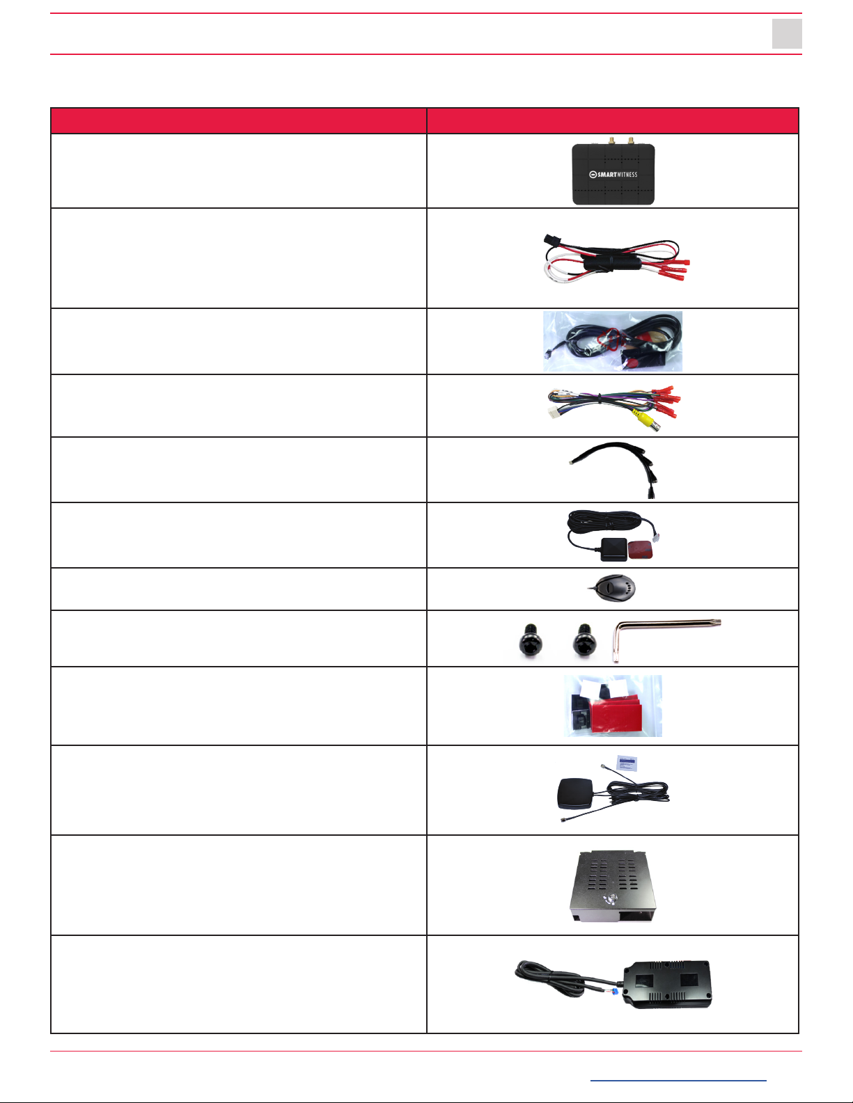
Package Contents
Product Name Image
CP4-NA-LTE Vehicle Recorder
SD and SIM cards pre-inserted
(if applicable)
Power Cable
BAT(+), IGN+, BAT(-)
Remote Controller (Panic Button)
with 3M adhesive
Video Output Cable and I/O triggers
Camera Input Cable
(4x Aviator input for Ch. 1-4)
GPS Antenna Module
Audio Microphone
Torx Screw (x2) and Torx T screwdriver
Velcro tape (x4) and Wire Splice clip (x5)
External 3G/LTE Antenna
Locking Enclosure/Mounting Bracket
(Optional Accessory)
External Wi-Fi Modem
(Optional Accessory)
smartwitness.com | 1016 Lunt Ave. Schaumburg, Illinois U.S.A. | Tel: 312.981.8774 | sales.usa@smartwitness.com
6R
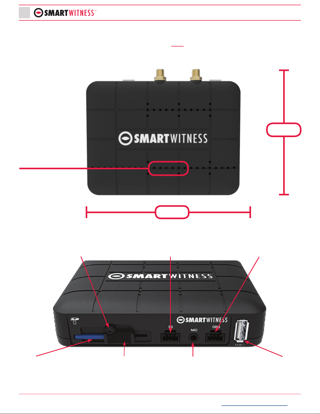
Hardware Overview
Watch the CP4-NA-LTE 360° Hardware Overview Video here:
Dimensions
Front View
Built in Microphone
3.55”
4.75”
Torx Screw Serial Port Debug Port
USB Input 2Microphone InputSlide LockSD Card Slot

smartwitness.com | 1016 Lunt Ave. Schaumburg, Illinois U.S.A. | Tel: 312.981.8774 | sales.usa@smartwitness.com
7
THIS IS VIDEO TELEMATICS
Rear View
Installation
1. Park the vehicle on a at service.
2. Turn o the engine before installing the CP4.
• The SD card and SIM is usually pre-inserted. If it’s not, insert card(s) in the unit, cover and tighten
the torx screw, locking the unit.
3. Find installation location for recorder and locking case (if
applicable).
• The default axis adjustments by device position is set as shown
on the right.
4. Install all the interior and exterior cameras with 3M dual sided adhesive
or hard mounting screws (conrm with customer as to the desired
installation method and locations).
• All four cameras will be connected to the CP4 recorder via the Camera Input Cable.
Camera Input
Harness (CH 1~4)
Video Output &
Alarm I/O Harness
LTE Antenna
Connectors
GPS
Input
USB1
Input
Power
Input
Remote Control
Input
Note: Please contact your service provider if the SIM or SD was not included in your package.
smartwitness.com | 1016 Lunt Ave. Schaumburg, Illinois U.S.A. | Tel: 312.981.8774 | sales.usa@smartwitness.com
8R
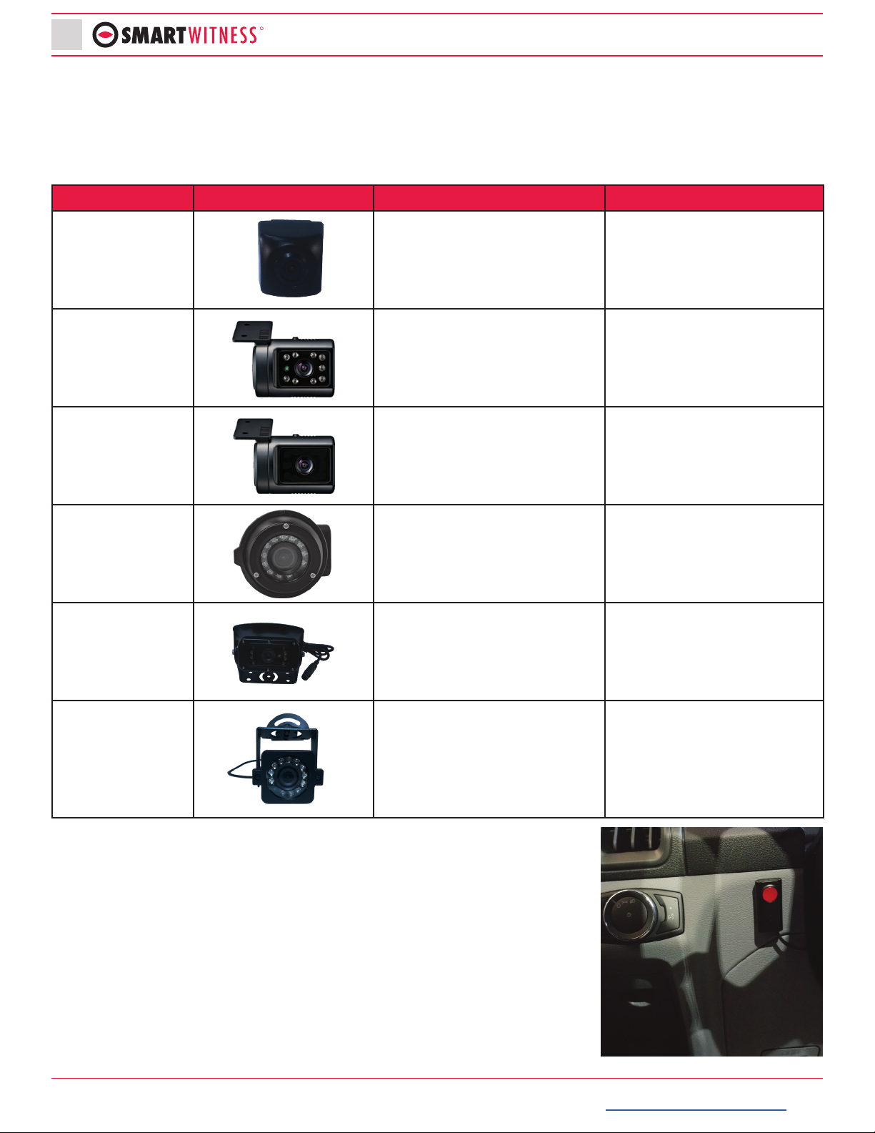
Accessory Camera Types
The CP4 has various accessory camera models available which should be installed
in the appropriate location. In the table below is a reference guide for the common
camera models.
Model Image Installation Location Notes
SVA032-A Road facing on Windshield
IP68 Weatherproof rated. L
bracket included for various
mounting options.
SVA040-A Driver Facing, on Windshield Infrared LEDs.
SVA045-AM Road facing, on Windshield No IR LEDs.
SVA035-A Outside of vehicle, either side
mount or rear backup view.
IP 69 Weatherproof. Camera
module can rotate 360° and
tilt up and down as needed.
SVA036-C Outside of vehicle. Rear
backup view
IP 69 Weatherproof. Sun/
rain shield included.
SVA033-C
Versatile camera, may be
mounted as driver facing
(inside), side view (outside), or
rear view (outside)
IP 68 Weatherproof. L
bracket included for various
mounting options.
5. Install remote control onto dash next to the steering wheel and
within reach of the driver.
6. Run camera cable(s) and secure in headliner and or other area so
no cables are exposed. Use provided wire clips if necessary.

smartwitness.com | 1016 Lunt Ave. Schaumburg, Illinois U.S.A. | Tel: 312.981.8774 | sales.usa@smartwitness.com
9
THIS IS VIDEO TELEMATICS
7. Connect all cables to CP4 Recorder. Secure the windshield mounted camera cables into the
headliner and down the A-Pillar.
Camera Channel Inputs
The CP4 has some restrictions on which cameras can be connected to which channel
inputs.
Restrictions
1. You cannot connect an “A” camera to channel 4.
2. Channel 2 and channel 3 must have the same camera type (either both “C” cameras or both “A”
cameras.
Acceptable Congurations
The table below shows acceptable camera input congurations:
Channel 1 Channel 2 Channel 3 Channel 4
A A A C
A A A -
A A - C
A C C C
C A A C
A A - -
CCCC
Required
smartwitness.com | 1016 Lunt Ave. Schaumburg, Illinois U.S.A. | Tel: 312.981.8774 | sales.usa@smartwitness.com
10 R
Unacceptable Congurations
The table below shows unacceptable camera congurations:
Channel 1 Channel 2 Channel 3 Channel 4
AAAA
A A C -
A C A A
A C C A
A C A C
A A C C
C C C A
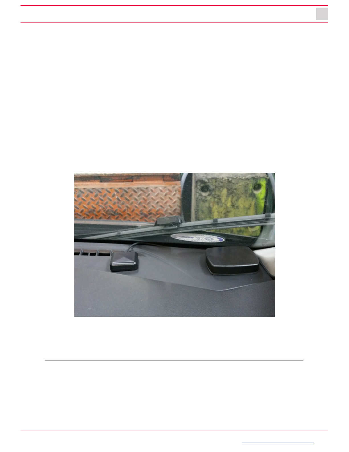
3. Route the GPS cable and LTE Antenna cable (if applicable) up the side panel and on the dashboard,
in view of the windshield (so it can have a view of the sky to acquire GPS signal).
• Activate the product in an area without large buildings to improve GPS reception.
• The temperature ranges for optimum operation of the GPS receiver in your car is -10 ~ 50°C.
smartwitness.com | 1016 Lunt Ave. Schaumburg, Illinois U.S.A. | Tel: 312.981.8774 | sales.usa@smartwitness.com
11
THIS IS VIDEO TELEMATICS
GPS Reception
GPS reception may be impaired under the following circumstances:
1. If there is an object at the end of the GPS antenna.
2. If your vehicle has metallic elements on the windsheilds.
3. If equipment generating electromagnetic waves that interfere with the GPS signal is installed in the
vehicle e.g. other GPS devices,such as a certain type of wireless activated alarms, MP3, CD players
and/or alarms using GPS.
4. If you are using a receiver connected by cable, electric interference can be avoided by simply
changing the location of the receiver (antenna).
5. On heavily overcast or cloudy days, if the vehicle is in a covered location such as under a bridge
or raised roadway, in a tunnel, an underground roadway or parking area, inside a building or
surrounded by high-rise buildings.
6. If GPS signal reception is poor, it may take longer to locate your current position when the vehicle
is moving than when it is stationary.
CP4 GPS and LTE antenna properly installed on the the vehicle dash.
DO NOT ATTACH THE LTE ANTENNA ONTO A METAL SURFACE
(Provide a minimum of 5 inches of separation between the antennas)

smartwitness.com | 1016 Lunt Ave. Schaumburg, Illinois U.S.A. | Tel: 312.981.8774 | sales.usa@smartwitness.com
12 R
Power Cable and Wiring
Lay out the power cable roughly where it will run once hidden behind the vehicle’s interior panels.
This gives you an idea of where to route the cable and how much slack to leave on the way down to
the vehicle’s power source.
Power Connection
Video Output Cable and I/O Harness (optional)
Power Specifications
Input: DC 12~24V, 3A
Required
Power (BAT+)
Ground (BAT-)
Ignition (IGN +)
Red
Black
White
White
Purple
Green
Orange
Blue
Gray
Brown
Black
Alarm In1, Voltage On/Off (3~70V)
Alarm In2, Voltage On/Off (3~70V)
Alarm In3, Voltage On/Off (3~70V)
Alarm In4, NC/NO (Open/Close)
Speed (TACHO)
RPM (TACHO)
Alarm Out, Low (OV) to High (5V)
Ground for Alarm In4 (NC/NO Circuit)
Video Output for connecting
LCD Monitor (BNC Female)

smartwitness.com | 1016 Lunt Ave. Schaumburg, Illinois U.S.A. | Tel: 312.981.8774 | sales.usa@smartwitness.com
13
THIS IS VIDEO TELEMATICS
Locking Enclosure (Optional)
Front View (open)
Rear View (closed)
Wi Modem Connection (Optional)
1. Connect external modem to only the USB1 input on the back of the CP4 unit.
2. The CP4 remote should have a solid blue and green LED to indicate network connection after
bootup.
USB 1

smartwitness.com | 1016 Lunt Ave. Schaumburg, Illinois U.S.A. | Tel: 312.981.8774 | sales.usa@smartwitness.com
14 R
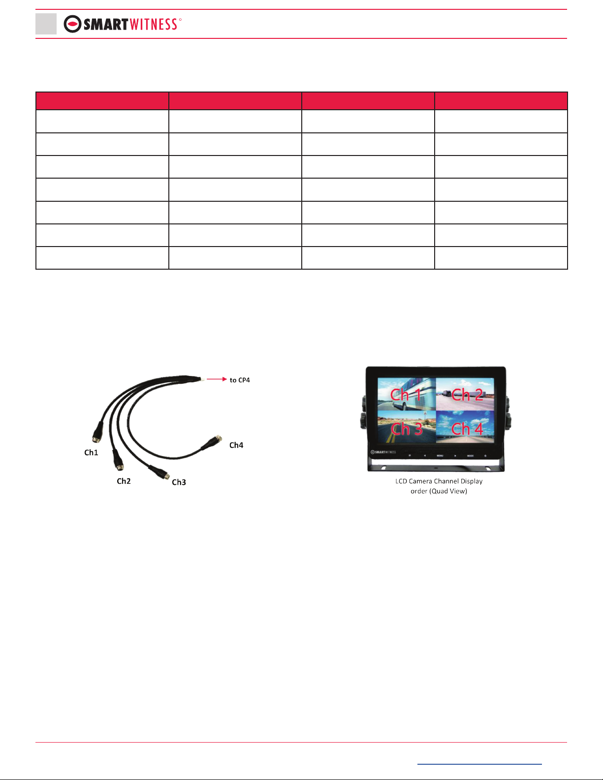
LCD Monitor Connection (Optional)
The LCD Monitor enable live display of up to four cameras.
1. Connect the 8-pin LCD monitor connector to the LCD monitor harness
2. Connect the 4pin female aviation connector to the video input cable on the LCD monitor
3. Connect the BNC female to the video out cable (BNC Male) on the CP4 harness
4. Make sure the CP4 video out/trigger harness is inserted into the “AV/OT Alarm Input” port on the
rear of the CP4
Remote Panic Button
The default display is Quad view (2x2) with all cameras shown, to change the video display channel,
press the [M2] button (see below) on the CP4 Remote Panic Button to select which camera to view.
Each press will change the camera on display with the last option being all camera views. Trigger
inputs are associated to live channel display. In other words, the backup camera is full screen, when
the vehicle is in reverse. Contact SmartWitness support for assistance with conguring device.
14
Video Input from DVR
(BNC Male to 4 pin
Aviator Female Connection)
2
3
M2 Button
M1 Button
Panic Button
Blue LED Record
Red LED Warning
Green LED Network
smartwitness.com | 1016 Lunt Ave. Schaumburg, Illinois U.S.A. | Tel: 312.981.8774 | sales.usa@smartwitness.com
15
THIS IS VIDEO TELEMATICS
Completion & Power-up
After installation of the CP4 and accessories into the vehicle you can turn on the ignition and CP4
recorder will power on.
1. There will be a sequence of red, blue & green LED lights on the Remote/Panic Button during the
boot-up process.
2. Once boot-up is complete:
• The red light will turn o and there will be only a solid blue and green (only for connected
device) light on. This indicates proper operation and recording.
• There is an error when the red light is blinking (see “LED Status” on page 17). Contact your
supplier or visit support.smartwitness.com to create a support ticket.
3. Login to install.smartwitness.com and complete the installation wizard to validate the installation
and generate the installation report.
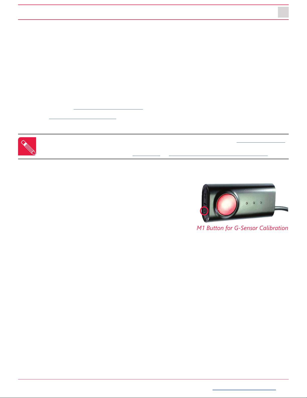
G-Sensor Calibration
G-sensor calibration is needed after installing the CP4.
1. Turn on the unit and wait until it starts recording.
2. Press and hold M1 button (located on the remote controller)
for more than 2 seconds.
3. You will hear a beep when you press M1, and then you will
hear another beep after 2 seconds. Upon the second beep,
you can release M1 button.
4. The calibration is completed within 2 seconds.
NOTE: You must rst go through mandatory training with SmartWitness to access install.smartwitness.com.
One you complete the training (about a 30-minute webinar), you will be provided login credentials. To
schedule training, please complete the online form at: smartwitness.com/become-installer.html.
M1 Button for G-Sensor Calibration

smartwitness.com | 1016 Lunt Ave. Schaumburg, Illinois U.S.A. | Tel: 312.981.8774 | sales.usa@smartwitness.com
16 R
Troubleshooting
1. The CP4 has a solid red light on as well as solid green and blue.
• Solid red LED indicates that one of the connected cameras is not receiving video signal.
»Please check the camera’s connection.
2. The CP4 red LED is blinking
• There is an SD card error/corruption.
»Please replace the SD card or contact SmartWitness.
• The new SD card must be initialized with the CP4 Conguration Tool for the device to function
properly, and the right settings must be applied.
• IF SD card is not initialized (blank), the CP4 will automatically initialize the SD card
»Apply the latest NAND settings, during the rebooting process.
3. CP4 red LED is solid.
• Please verify proper voltage and amperage is being supplied to the Red (BAT+) & White (IGN+)
cables on the power harness and that the black cable is properly connected to BAT(-).
4. The CP4 green LED is blinking or o.
• Verify the SIM card is registered with the cellular network.
• Remove and re-insert the SIM card, vering the SIM is inserted correctly
• Cycle power to the camera.
smartwitness.com | 1016 Lunt Ave. Schaumburg, Illinois U.S.A. | Tel: 312.981.8774 | sales.usa@smartwitness.com
17
THIS IS VIDEO TELEMATICS
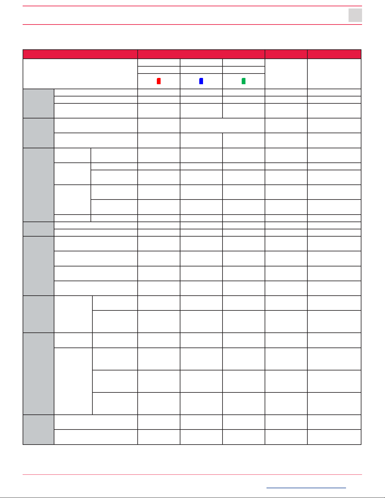
LED Status
Status / Step LED Buzzer Voice
Warning Record Network [Remark] to hear
the voice, audio
output cable to
speaker
Red Blue Green
Startup
Booting step1(0~20) On O O
Booting step 2 (20~30) On On and O O
Booting nished (30, 1 sec. ) On On On Beep (1000
Hz, 200 ms.) Beep ( 1 time)
Power O
During power o O Simultaneous ashing (blink
rate: fast)
Power o nished O O O Beep (500 Hz,
150 ms.)
Record
Continuous
Record Recording On
Event
Record
Stand By On
Recording Flashing (blink
rate: fast)
Dual Record
Continuous
Recording On
Event
Recording
Flashing (blink
rate: fast)
No Record Not Recorded O
Network 3G Network Device Ready On
Communication On
Function
SD Initialize (format) O On and O O and On Beep, 1 time
(continuously)
G-Sensor Calibration Beep (after 2 sec.)
Beep - Beep
FW Upgrade On and On,
O and O
On and On,
O and O
Button Press Beep (1000
Hz, 200 ms.) Beep
Warning System
Warning
SD card full Flashing (blink
rate: fast) O Beep x 4 (3 times)
Video loss
Video STD
error
On
Error Record Error SD error, No
SD, Write Fail
Flashing (blink
rate: slow)
O Beep x 4 (3 times)
Network
Error
3G Network
device error,
SIM error
O
Data Network
connection
error
Flashing (blink
rate: slow)
DMS
communicate
error
Flashing (blink
rate: slow)
Event
Trigger
G-Sensor, Panic Button,
Alarm-In
DingDong x2
(1 time)
Over Speed Beep-Beep x2
(1 time)


smartwitness.com
SmartWitness is a world leading designer, manufacturer, and
supplier of in-vehicle cameras, recorders, and software. Our lineup
of IOT dash cameras and accompanying REST API have allowed
SmartWitness’ video and data to be seamlessly integrated with
GPS tracking, telematics and eet management software, ushering
in the new era of Video Telematics. Our industry-leading safety
technology has produced exceptional results for our clients
and solutions which undeniably redene the way vehicle risk is
analyzed.
R
Video Evidence Capture
High-Resolution cameras capture
images of the road, inside and
outside the vehicles’ sides and rear
views.
GPS Location Recorded
Built-in GPS/Glonass provides precise
event location, route, vehicle speed
and direction.
Network Connected
Cellular connectivity provides real-
time images, live-location, and on-
demand HD video upload.
Events & Driver Analyzed
Detailed telemetry data enables
accurate scoring for the purpose of
driver coaching and reducing claims.
SmartWitness UK
2 Valley Point, Beddington Farm Rd.
Croydon CRO4WP
E: sales @smartwitness.com
T: +44 (0)1483 397005
SmartWitness USA
1016 Lunt Ave., Schaumburg, IL 60193
T: +1 (312) 981-8774
Table of contents
Other Smart Witness Measuring Instrument manuals


Popular Measuring Instrument manuals by other brands


Netafim
Netafim Octave Installation & user guide

WATANABE
WATANABE WPMZ Series Communications manual

Electron Microscopy Sciences
Electron Microscopy Sciences 72907-01 Instructional manual

Brigade Electronics
Brigade Electronics ZoneSafe RFID user manual

Huvitz
Huvitz CRK-1 Service manual

Leica
Leica Rod Eye 180 user manual