Smart Witness SVC1080-LCS User manual

SVC1080-LCS
VEHICLE JOURNEY RECORDER
USER GUIDE
v1.1
•Thank you for purchasing the SVC1080-LCS Journey Recorder.
•Please ensure that you read and understand this USER GUIDE
before installation.
•Please save the USER GUIDE in an easily accessible location.
•You can download the PC or MAC Viewer Software from:
http://support.smartwitness.com

2
Safety Advice
GPS Reception
Contents
Introduction
Functions
LEDs & Buzzer Specification
Installation
Software User Guide
Software Installation
Initialize SD Card
Settings
Pc Viewer Software Viewing Settings
Open The SD Card
Playback
Log File Playback
Save Jpeg And AVI/MP4 File
Print Image
Backing Up Files
GPS Log To KML Converter
Driver Report
Analysis Criteria Settings
Grading Criteria Settings
Grading Method
Graph Display Settings
SPECIFICATION
Appendix Recording Time Table
Appendix Upgrade
Technical Support And Warranty
INDEX
3
4
5
6
8
10
11
12
13
14
15
17
18
19
20
21
22
23
24
25
26
28
31
32
33
34
35
36
3
Caution
Damages due to production malfunction, loss of data, or other damages occurring
while using this product shall not be the responsibility of the manufacturer.
Although the product is a device used for recording videos, the product may not save
all videos in the case of a malfunction. In the case of an accident, the sensor may not
recognize the shock when the impact is light and as a result it may not begin
recording automatically.
SAFETY ADVICE
CAUTION
RISK OF ELECTRIC SHOCK
DO NOT OPEN
CAUTION: TO REDUCE THE RISK OF ELECTRIC SHOCK,
DO NOT REMOVE COVER.
NO USER-SERVICEABLE PARTS INSIDE.
REFER SERVICING TO QUALIFIED SERVICE PERSONNEL.
WARNING:
TO PREVENT FIRE OR ELECTRIC SHOCK HAZARD, DO NOT EXPOSE
THIS APPLIANCE TO RAIN OR MOISTURE.
Caution
Install the product where it does not block driver’s visibility and where there is
no airbag installed. This could cause an accident or might injure passengers in
case of accident
Please make sure you follow the safety advice/instructions given in the user guide.
Caution
RISK OF EXPLOSION IF BATTERY IS REPLACED BY AN INCORRECT TYPE.
DISPOSE OF USED BATTERIES ACCORDING TO THE INSTRUCTIONS.
Battery for RTC(Real Time Clock) inside

4
GPS Reception
1. Activate the product in an area without large buildings to
improve GPS reception.
2. The temperature range for optimum operation of the
GPS receiver in your car is -10 ~ 50°C.
3. When using the product for the first time or after a long
period (more than three days), it may take a little longer to
recognize your current location.
It may take between five and thirty minutes to get GPS reception.
GPS reception may be impaired under the following circumstances
1) If there is an object at the end of the GPS antenna
2) If your vehicle has metallic elements on the windshields
3) If equipment generating electromagnetic waves that interfere with the GPS
signal is installed in the vehicle e.g.: Other GPS devices such as a certain
type of wireless activated alarms, MP3 and CD players and camera alarms
using GPS.
4) If you are using a receiver connected by cable, electric interference can be
avoided by simply changing the location of the receiver (antenna).
5) On heavily overcast or cloudy days, if the vehicle is in a covered location
such as under a bridge or raised roadway, in a tunnel, an underground
roadway or parking area, inside a building or surrounded by high-rise
buildings.
6) If GPS signal reception is poor, it may take longer to locate your current
position when the vehicle is moving than when it is stationary.
The commercial purpose GPS has the average range error of more
than 15 meters and the range error could be more than 100 meters
due to environmental conditions like buildings, roadside trees etc.
5
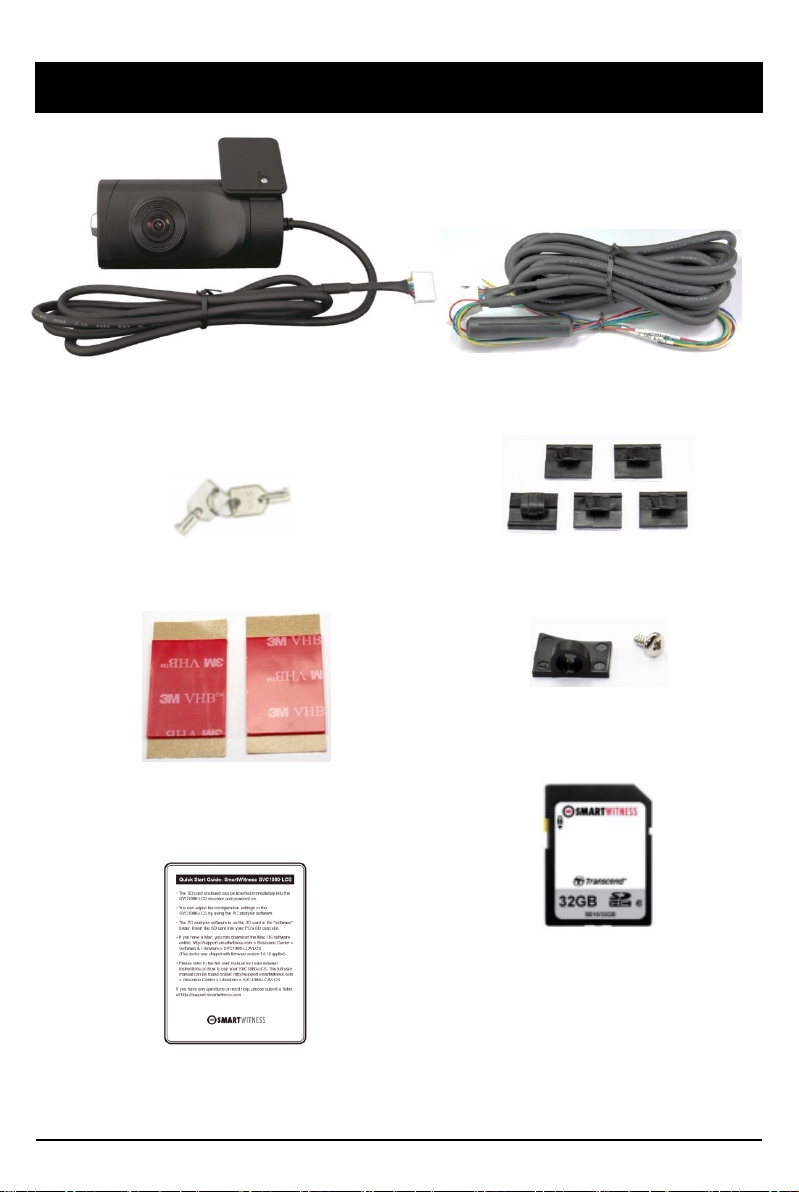
CONTENTS
SVC1080-LCS
Vehicle Recorder
Wire Splice clips (5ea)
3M Adhesive for Windshield mount
(2ea)
Power Cable
Quick Start Guide
Angle Stopper and screw (2ea)
Key for SD cover (2ea)
*PC software is located on the SD
card in the “software” folder or can
be downloaded online at support.s
martwitness.com (Mac software als
o available online)
SD Card
6
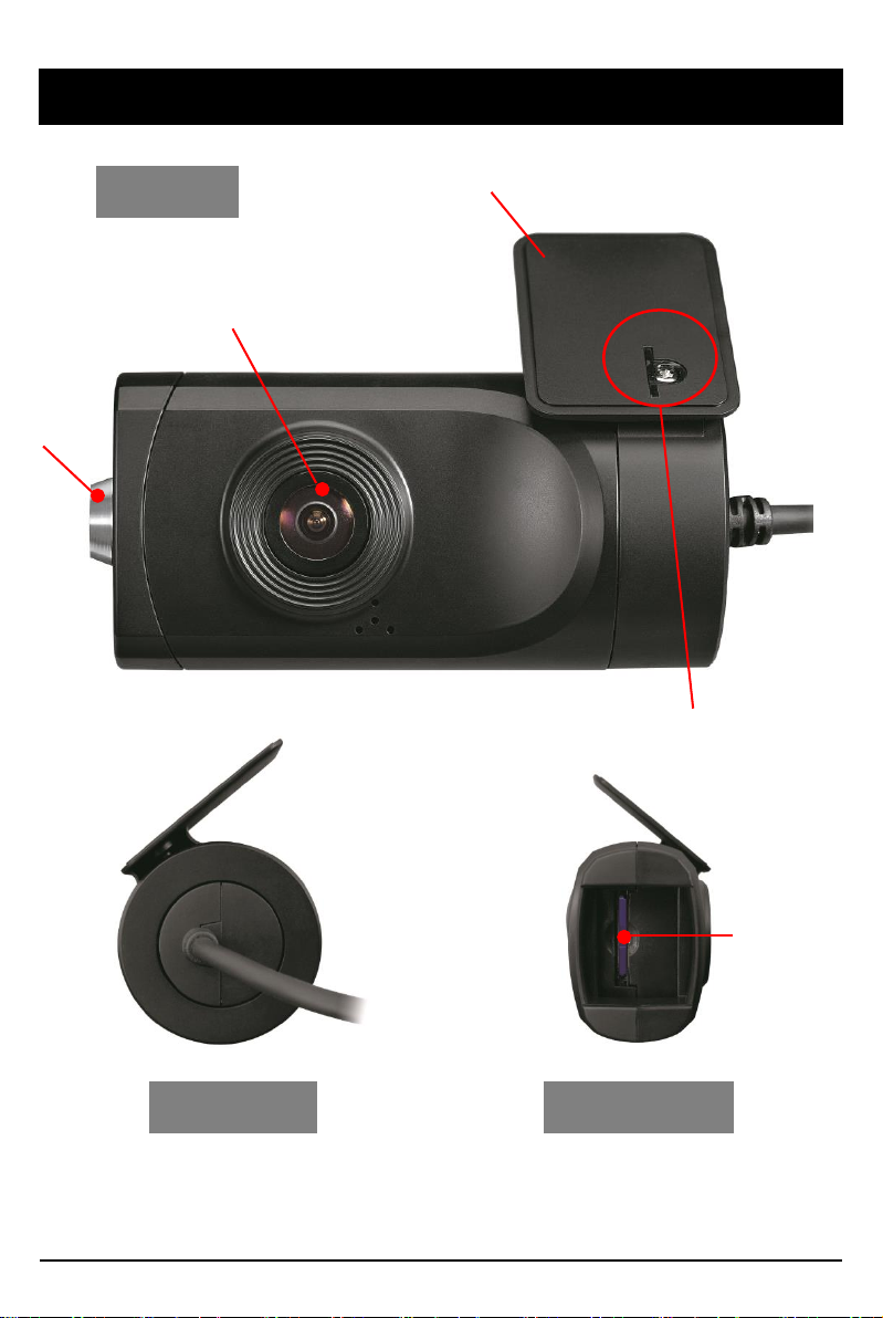
INTRODUCTION
Camera Lens
Bracket
FRONT
Left side Right Side
SD
Memory
Card Slot
Lock
Angle Lock by screw

7
INTRODUCTION
REAR
Record LED
BLUE LED
Warning LED
RED LED
Panic Record Button
G-Sensor Calibration button
Power Cable
Black (Ground)
Red (Power, IGN+)
White (External panic button+ )
Blue (External panic button -)
Green (Alarm out1), Low(0V) to High (5V) 2seconds
Yellow (Alarm out2), Low(0V) to High (5V) 2seconds
External Panic Button
(optional Item)
Cable length: 2m90cm
Button Case Size: 18 x39x10 mm

8
FUNCTIONS
Automatic Booting
Once the SVC1080-LCS has been wired to your car power source the SVC1080-LCS
will be boot up, this will take around 1 minute for the unit to be ready to record.
The default setting for record is the continuous recording at 30fps, 720P
resolution. This setting allows for separate event and panic recordings. On this
setting the SD card storage may be used up quicker and depending on the settings,
overwrite or stop recording when full. To avoid losing valuable data, back up data
to a separate storage or PC device after any incidents.
Continuous Record (When Record mode set as “Continuous”)
This is the default mode for recording. In this setting the unit will begin recording
after boot up and record the entire time the unit is powered.
The resolution and frame rates can be set as per your requirements. You can change
the configuration of the recording using the SVC1080-LCS Software. To do this,
please see the ‘Settings’ section on page 15.
NOTE: The unit will not start recording immediately after power on. It takes
around 1 minute for the built-in power backup system to charge. Thereafter, the
internal flash memory will be ready to record.
Event Record (When Record mode set as “Event”)
The unit will record when triggered by either an impact or a push of the ‘PANIC’
button. In such events, 15 seconds of pre and post events will be stored separately on
the SD card.
NOTE:
When recording at 30fps, (1080P HD) resolution, separate event files (Shock and
Panic) will not be stored. If you wish to keep separate event files, change the
settings to a lower resolution or frame rate.
For example, 1080P @ 10fps or 720P @ 30fps
Parking mode: If G-Sensor value is not changed during 5 minutes, the record
frame rate will be automatically change to 1FPS. When a vehicle starts to move
then the parking mode will switch off automatically and start the continuous
recording immediately
This “Parking mode” can be set when the record mode set as “Continuous”.

9
FUNCTIONS
G-Sensor Calibration
1. Install the unit and park the vehicle on a flat surface .
2. Turn on the unit and press the blue button one time.
3. Then calibration will be done with “beep” sound.
Built-in power backup (Super Capacitor)
When power to the unit is interrupted, SVC1080-LCS creates the last
file using the internal Super Capacitor.
Time and Date
There are no time and date settings as the SVC1080-LCS gets this information
from the GPS satellites.
SD Memory Card Format
Please format [initialize] the SD card using the PC viewer software.
Power off vehicle and take out SD memory card
Turn off the power and then check the BLUE LED light. Once the LED light
is not on, you can now safely remove the SD memory card.
[SD un-mount] Press and hold the small red button for 3 seconds and release it.
When the blue LED goes solid ON, then you can remove the SD card safely.
[SD re-mount] Insert the SD card into the SVC1080-LCS, then press and hold
the small red button for 3 seconds. This will cause the SVC1080-LCS to reboot.
Take out and Insert SD memory card during power on
There are 2 ways to remove the SD card, the first requires the vehicle to be powered
down and the second you can safely remove the SD with the vehicle is powered on.
Please see below details for both methods.
Safely Removal SD Card

10
Status BLUE LED RED LED BUZZER
Booting
on
on
off
Upgrade
heartbeat
heartbeat
off
Continuous
recording
4
sec / 1sec
off
off
Triggered
Event
recording
0
.5sec on/off
off
100
msec on
SD
fault
off
0
.5 sec on/off
off
System
fault
on
on
off
SD
unmount
on
off
0
.1sec on 2 times
SD
reset
on
off
0
.1sec on 2 times
SD
Full
off
2
sec / 2sec
off
G
-Sensor calibration
-
-
0
.1sec on 1 time
Parking
Mode
8
sec / 1sec
off
off
Power
off
off
off
off
BLUE LED (RECORD)
The blue LED shows the power is on.
During the continuous recording: blue LED will be on 4seconds and off 1second.
During the event recording: blue LED will be on 0.5 second and off 0.5 second.
During the Parking mode: blue LED will be on 8seconds and off 1second.
RED LED (Warning LED)
The red LED will be turned on when system failure.
Buzzer
A ‘Beep’ sound will occur when event recording starts (this can be turned off, if
required by uncheck “Event Beep” at Settings)
LEDs & BUZZER Specification

11
INSTALLATION
WARNING: SmartWitness installations should be performed by a quali
fied individual or installation professional only. Working with a vehicle'
s power system can be dangerous to both you and your vehicle. This ins
tallation is intended only to be a guide since vehicle designs and power/
input sources can vary significantly from vehicle to vehicle.
If you need to schedule a professional installation service in the USA
for your SmartWitness device(s), please visit http://smartwitness.com/sc
heduleinstall and submit the online form.
Please download installation guide here:
https://smartwitness.com/us/pdf/SVC1080LCS-Install-Guide.pdf

12
SOFTWARE USER GUIDE
PC Viewer Software
PC SYSTEM REQUIREMENT
If the PC does not meet the minimum system requirement, the PC Viewer
Software may not function properly.
OS Windows Vista. Windows 7, Windows 8/8.1, 10
CPU Core 2 Duo 2.5GHz or Higher
RAM 2GB or Higher
Interface SD Memory Card Reader
HDD
Free space
Install : 55MB or Higher
Backup : 4GB or Higher
Display 1024 x 768 pixel/True Color or higher
Recommended PC specifications for PC Viewer Software

13
SOFTWARE INSTALLATION
1. Connect the SD card into your PC (if your computer does not have and
SD card slot use the USB SD card reader) and open the “My Computer”
2. Right-click the “FHDREC1” drive and select [Open]
3. Double click [SETUP.EXE] in the [pcsw] folder.
4. Select the language and then follow the dialog box prompts.
5. The “SmartWitness SVC1080-LCS” icon will be displayed on your desktop.
NOTE: To Un-install the PC Viewer Software
Make sure the program is not running and open the ‘Control Panel’
Select ‘Remove Program’ and remove the PC Viewer Software.
The PC Viewer Software is on the provided SD card. (Also available on our
website.)
14
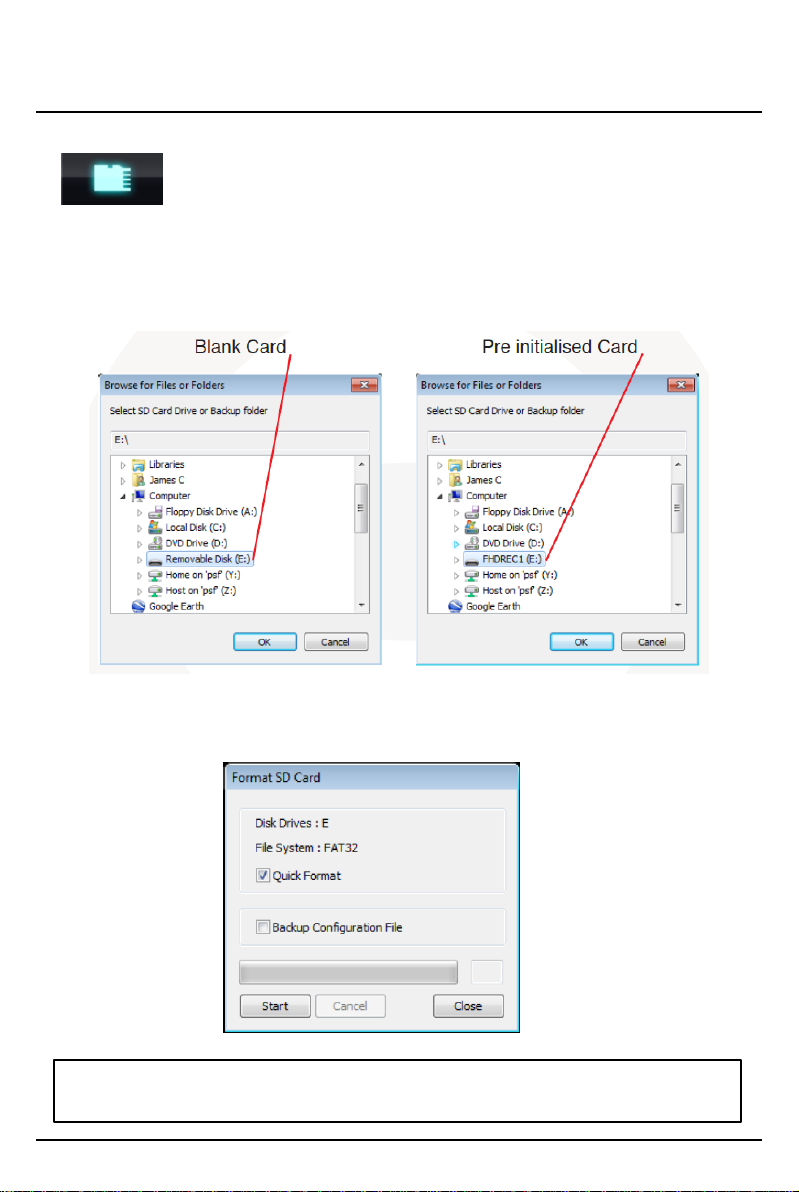
Initialize SD Card
To initialize the SD card, click on the above icon and you will be
presented with the following screen to choose the card to initialize. Click ‘Ok’
when selected.
On the following screen, check the ‘Quick Format’ button and uncheck the
‘Backup Configuration File’ and click ‘Start’ to begin initialisation.
initialize SD Card’ Icon
NOTE: The PC Viewer software will automatically be copied to [pcsw]
folder on the SD card.

15
Settings
[Settings] icon
This option allows you to adjust the settings on the recorder. Click the above
icon to bring up the screen below.
Record Mode
Event (Automatically starts recording by G-sensor or Panic button.)
Continuous (Always recording when powered by DC 12/24V.)
Resolution
VGA (640x480), 720P (1280x720), 1080p HD (1920x1080).
Frame Rate
Adjust the frame rate from 30fps, 15fps, 10fps, 1fps
Password
Enter 4 numbers from 1000 to 9999 as a password
Overwrite Recordings
This function allows the unit to overwrite old files on the SD Card
automatically. You can overwrite the continuous, panic or G-Sensor
recorded files.
Record Audio
Turn the audio recording on or off.

16
Settings
Parking Mode
Set Record Mode as Continuous and then you can check the Parking Mode box.
If G-Sensor value does not change for 5 minutes, the record frame rate will be
automatically change to 1FPS. When a vehicle starts to move then the parking
mode will switch off automatically and start the continuous recording
immediately
Event Beep
Turn on the event beep to make the unit ‘beep’ when the G-sensor has been
triggered or the Panic button has been pressed.
G-Sensor Sensitivity
The shock sensor sensitivity can be set to ‘Simple setting Mode’ or ‘Custom’. Set
to easy allows you to set the sensitivity to 9 (High), 5 (Medium) or 1 (Low).
In custom set, you can set 3 different shock sensor values individually.
Auto adjust G-Sensor to Vehicle speed
Once it checked, SVC1080-LCS will automatically decrease the G-Sensor
sensitivity at higher vehicle speeds to compensate for the naturally added G-
forces that are experienced due to velocity.
GPS Record Time
Select the total log file size.
About 2days (80MB)
About 7days (280MB)
SD Error Beep
Turn on the SD Error beep to make the unit ‘beep’ when the SD Error occurred.
Alarm Out1
High voltage 5V out when G-sensor or Panic triggered. (Low to High 2 seconds)
Alarm Out2
High voltage 5V out when SD error occurred. (Low to High 2 seconds)
Date/Time
Automatically synchronize with GPS time. However this manual time setting is
also available to use the unit at the inside of building.
Vehicle ID
Set a vehicle ID for the unit.
Init SD Card (Initialize SD Card)
All video and GPS data will be deleted and create necessary folders and copy
necessary files into the SD card.
Initialize Data
Click this option to delete all recorded files on the SD card. Please backup all data
files you wish to keep before doing this.
17
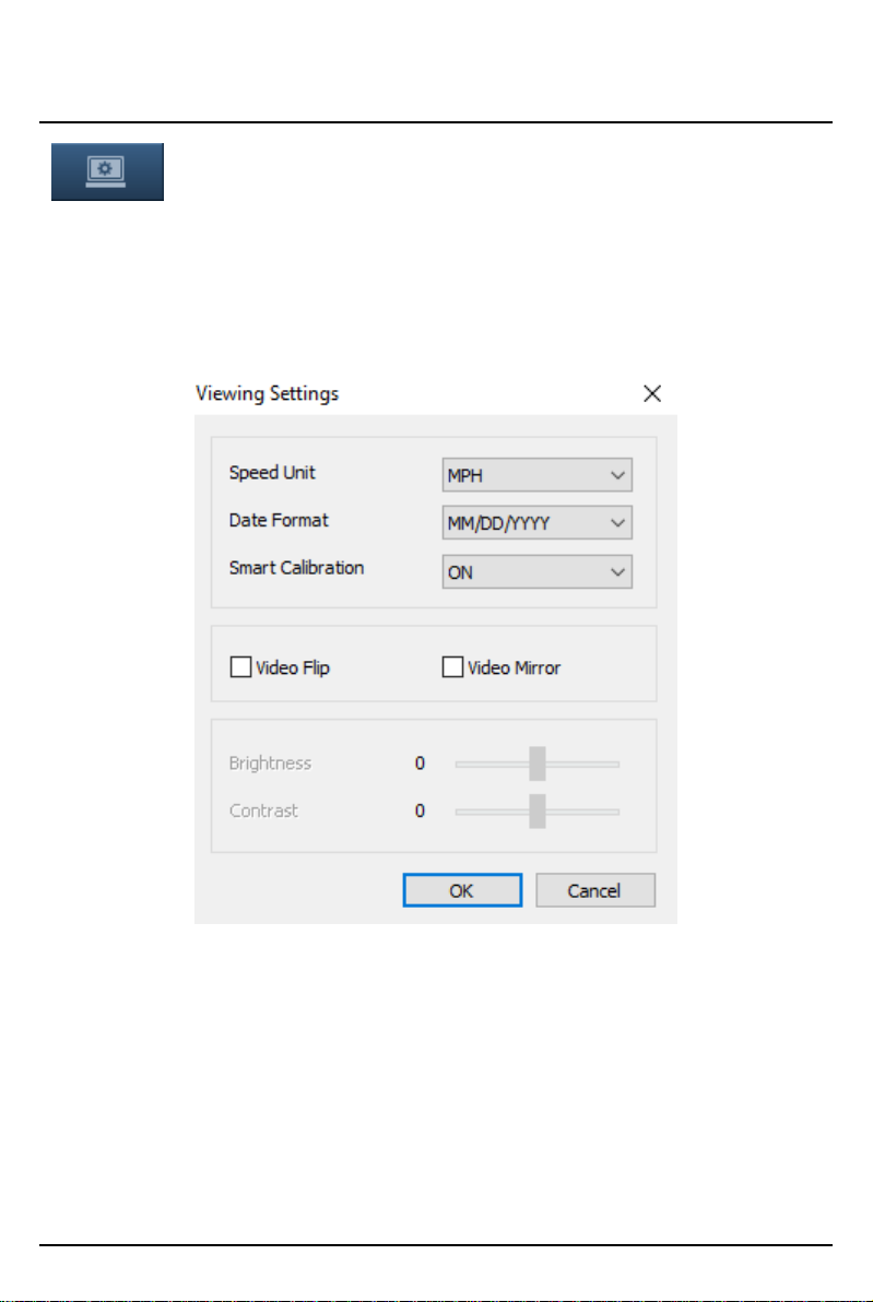
The ‘speed’ unit & ‘date’ formats can be changed with this Viewing settings.
Video Flip, Video Mirror, Brightness and Contrast can be set in this Viewing
Settings
Auto Calibration: This option is for the G-Sensor graph display.
OFF: Original G-Sensor graph.
ON: Calibrated G-Sensor graph. Shows the differential value of each axis.
PC Viewer Software Viewing Settings
This setting is for the PC Viewer Software itself. To set the Recorder, refer to
page 15.
Viewing settings
18
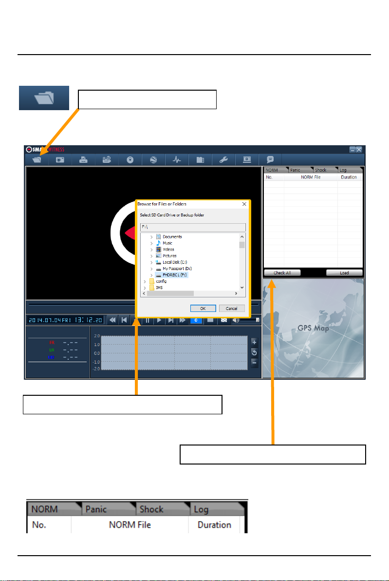
Open the SD card
①Click “Select SD Card” icon
②Select the SD card drive and click “OK”
③Click “Check All” and then click “Load”
Insert the SD card into your PC
Select tab to load the Panic Events or G-sensor Events or Log files.
19
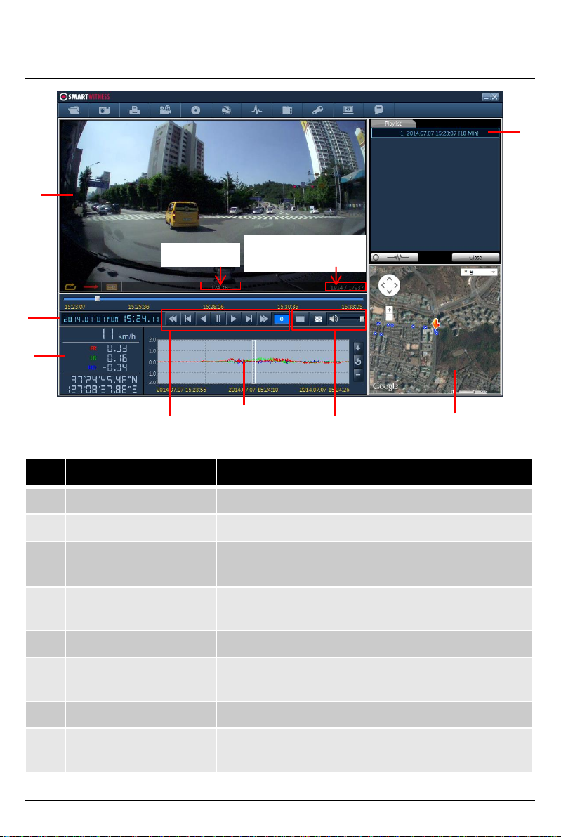
PLAYBACK OSD Functions
No Icon Description
1 Video Display Shows video data
2 Date & Time Displays time and date of video data
3 Driving Info Shows speed, accelerometer values on the 3-axes
and GPS co-ordinates
4 Video Controls Video playback controls, playback speed options:
x1, x2, x4, x8, x16
5 Accelerometer Graph Displays accelerometer values on graph
6 Display and sound
controls
Select display to be continuous or frame by frame
and sound level
7 Map Shows location and route using Google Maps
8 Data File List Select files to view:
Continuous, panic, shock, Photo
1
2
3
Frame Size Display Frame/Total
frames number
4567
8

20
LOG FILE PLAYBACK
Select [LOG] Check the log from the log list using mouse or click [Check All]
button. Then click [Load] button.
GPS speed, G sensor X value, G sensor Y value, G sensor Z value,
can be checked first on the small check box at right side of each value.
Then input data for data sorting.
If there is recorded video data, [Switch] or [G Sensor] mark will be
displayed on list.
Log data Log data will be recorded during driving even if there are no
events. The total log data size can be set from 2 days, to 31days. The log data
overwrites the oldest data. Using this log data, you can use the data sorting
function which helps to find a specific data like more than 80mph(or 80km), for
example.
Search button
Input sorting data
G-sensor graph
G sensor X value: Front & Back (like Quick brake or Quick Start)
G sensor Y value: Left & Right (like Quick Turn)
G sensor Z value: Up & Down (like prominence and depression)
Table of contents
Other Smart Witness Measuring Instrument manuals


