Smart Witness CP4 User manual

SmartWitness CP4
Device Configuration Guide
This is Video Telematics.

CP4 Setup and Configuration
1. Download the CP4 configuration tool
2. Install and open the configuration tool:
1. Insert SD Card into your PC (Max 128GB
SD card supported)
2. Click ‘Initialize SD Card’
3. Select the SD card from File Explorer
4. Click “Start” to initialize
3. Apply your desired settings (or click “Open” to
load existing settings)
4. Click “Save to apply to SD card
5. Eject Card safely from your PC
CLICK HERE FOR VIDEO DEMONSTRATION
*SD cards can also be removed from the CP4 to review video and
data. For this, the SmartWitness PC viewer software is required
which you can download here or visit Support.smartwitness.com
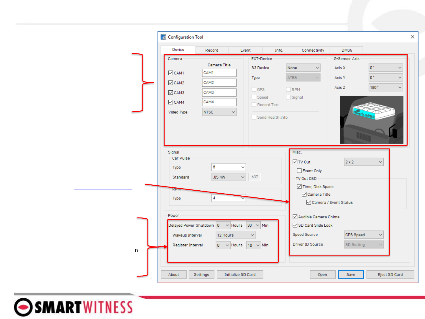
Device Tab
*See pg 9 for more details on G-Sensor thresholds.
Camera
Enable the desired camera channels.
EXT-Devices
Used to enable S3 port in order to
connect an external device (such as
RFID reader).
Misc.
•TV Out: enabled to provide signal to the
monitor. Event Only option turns off the V/O
signal completely unless it’s configured on the
event tab
•TV Out Event Only: When enabled, there will be
no video signal at all unless event trigger is set
(see Liveout Channel setting on Event tab)
•TV Out OSD: set what information is displayed
on the LCD monitor (see here for more info)
•Audible Camera Chime: turn audible alert on or
off (audible alarms can be individually turned
on/off per event).
G-Sensor Axis
Set the CP4’s installed position. This is
Important for proper G-Sensor calibration and
accurate drive data reporting.
Delayed Power Shutdown: Amount of time CP4
stays powered on after ignition is turned off.
Wakeup Interval: Time interval in which the CP4
will automatically power up again after shutdown
Register Interval: How long the CP4 stays
powered on during the wakeup interval.

The settings shown here are recommended for Telematics solutions using Smart API
Audio recording can be turned on or off here
Record Tab
Resolution: chose from D1, HD (720p) or FHD (1080p)
Frame Rate: Choose from 30, 15, 10, 5, 4, 3, 2, or 1
Quality: Standard, High, or Super. (The lower the quality,
the more compressed/lossy the video output).
Please refer to SD storage calculator to determine
storage times based on the chosen settings here
Record Modes
Event: Only events are recorded, event video
duration determined by the pre & post event setting
Continuous: Records video continuously, no events
(events can still be sent to Smart API server if
configured on the Server tab)
Dual Mode: Records continuous at 1FPS + events at
the specified FPS
*If Dual Mode is set, you can adjust the SD card
partition for event and continuous video here
Telematics Data (DRV file) is recorded and
stored separately from video and events. Set
the local storage duration here.
Parking Mode reduces the FPS to 1
when the vehicle is idle for 5 minutes
(Continuous Mode option only)
Tamper Detection ensures that MDT files are not
tampered/manipulated. When using SmartWitness
PC software, any MDT file which is not an original
MDT file will populate a warning. Tamper setting
must also be enabled on the PC software
*G-Sensor Sensitivity
Settings
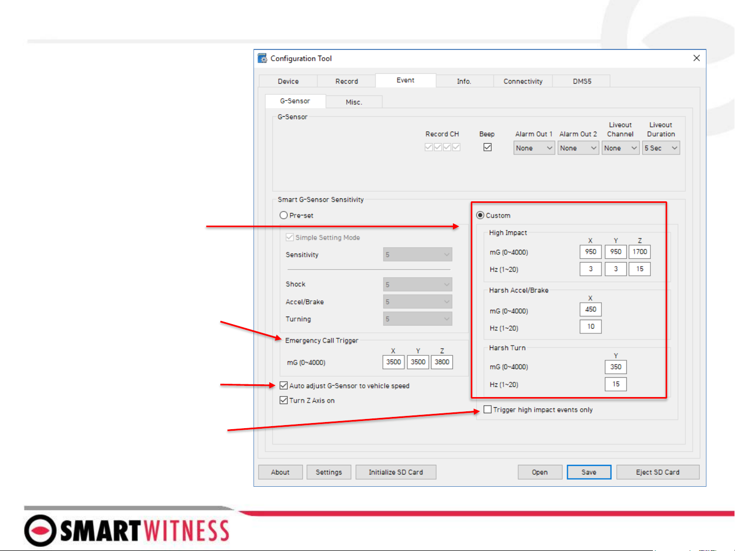
Event Tab –G-Sensor
Check this box to increase G-Sensor
threshold at higher vehicle speeds.*
*See pg 10 for more details on G-Sensor thresholds.
When checked, only Ecall and Shock
events will trigger (accel, brake, and
turn events will be ignored)
Ecall is a severe impact G-Sensor
which can be configured to send
emergency notifications
separately from lower level shock
events.

The Event tab will allow you to specify which
events will trigger a recording (Event record
mode or Dual record mode only).
If using the optional alarm input triggers
(Alarm1: white, Alarm2: Purple, Alarm3:
Green, Alarm4: Orange) then you need to
check the box(s) here and label them
according to the input type (i.e. horn, lights,
door open, etc.)
Also the input type should be selected
(NC/NO, or 12V ON/OFF).
NOTE: Alarm4 may not be supported by
older versions of CP4 hardware. CP4
devices shipping from August 2018 and
forward will support this 4th alarm input.
Alarm Out, if selected, will send a 5V output
from the Yellow wire to a 3rd party device
for the duration selected in the dropdown.
Liveout Channel: Which camera channel will
be displayed on LCD when trigger is
activated.
Liveout Duration: How long the camera
view will stay displayed after trigger is off
Check the boxes next to each event you want
triggered.
You can also set speed thresholds here if
you’d like to record over speed events. (This is
raw vehicle speed and does not account for
road/posted speed limits)
Check “Beep” if you’d like an audible chime to
alert the driver when the event occurs
Event Tab - MISC

Time setting is not necessary as the PC Viewer
software and Smart API both adjust the standard
UTC time to local time automatically
Info Tab
SD Card auto format feature enables the CP4 to
perform automatic maintenance on the SD cards
when there is an issue. SD cards need to be re-
formatted occasionally over time. This unique
feature reduces the administrative burden of
managing SD card formatting amongst your fleet
NOTE: SD card data will be deleted when an
auto-format occurs
Vehicle No & Driver ID can be added here. These
values will be able to be watermarked on the AVI
converted video using the PC software.
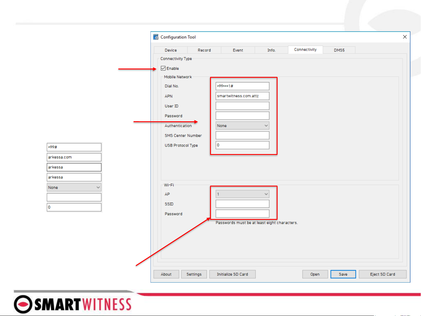
When using CP4 as a connected device,
“Enable” the connectivity here
Add Mobile Network provider details here
If using SmartWitness SIM (AT&T), the
APN should be as shown
If using SW UK (O2 Arkessa) below
Connectivity Tab
You can enable WiFi connectivity instead
of celluar connectivity with the use of an
approved WiFi USB dongle. The AP must
be secure with WPA/WPA2 encryption and
have a password of at least 8 characters
(cannot be an open network).
You can set up to 10 WiFi SSIDs. CP4 will
scan for as many networks as are added
here in its settings
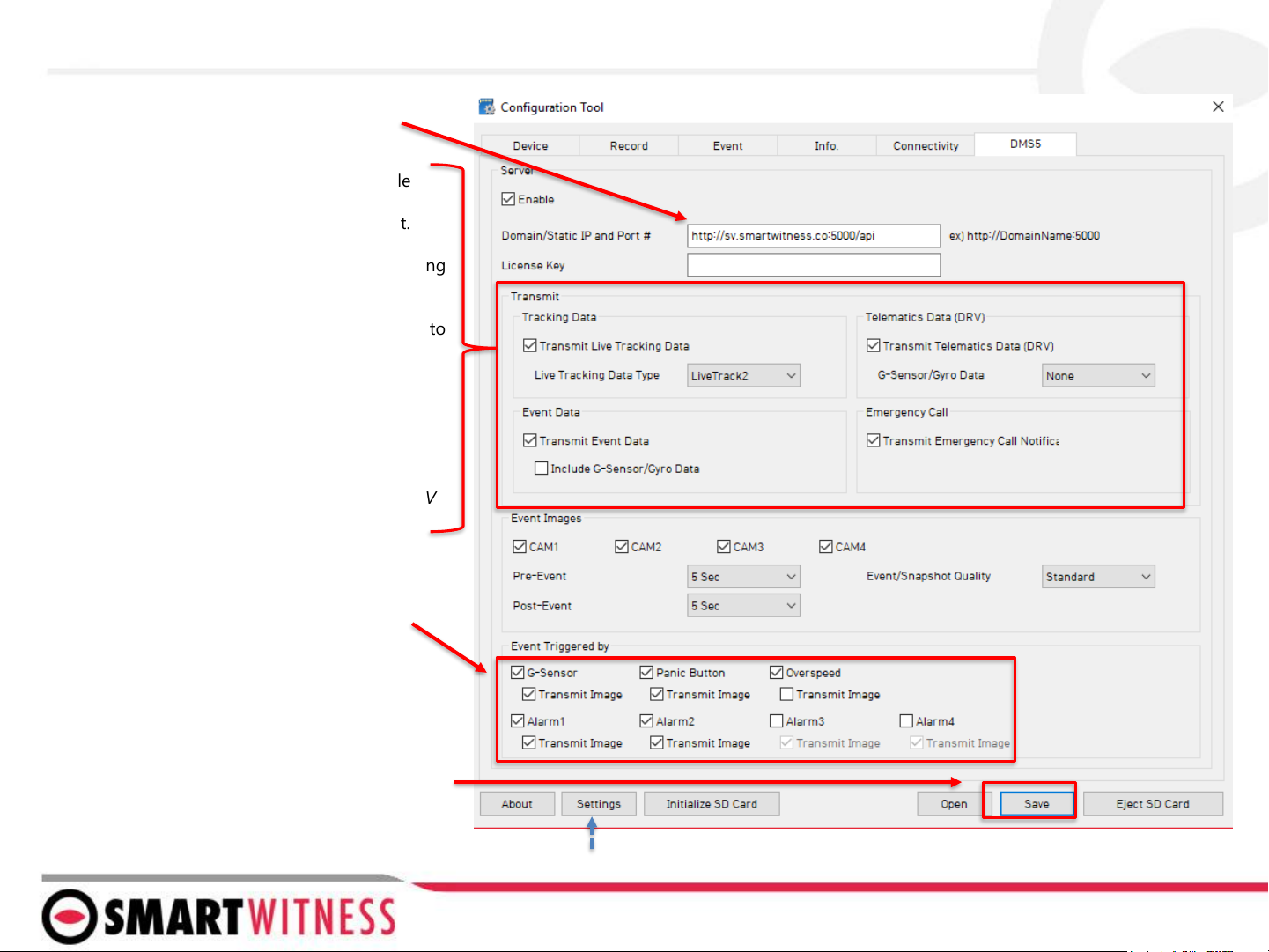
SmartWitness or your service provider will
provide you the URL and (if necessary) the
License Key to enter here.
Select the events here which the CP4 will
transmit to the server in real-time. These
events will transmit instantly even if CP4 is
set as “Continuous” record mode.
Click ‘Save’ and select the “FHDRM” SD drive
when prompted. This will save your
configuration to the card. Wait for the
software to confirm the settings have been
applied to the SD Card.
You can now eject the SD from your PC and
insert into CP4 and power on.
You can also save the settings as default to the config tool software by clicking “settings” and “Save
current settings as default”
Server Tab
Transmit Live Tracking Data: Check to enable
http posts from the CP4 to server. Livetrack2
contains GPS coordinates. LiveTrack3 does not.
Transmit Event Data: Check to enable CP4 posting
event notification and images to the server.
Transmit Telematics Data: Check to enable CP4 to
send DRV data (static/compressed file containing
drive data from every second the vehicle is in
operation.
Transmit Emergency Call: Check to transmit
ecall/Severe Shock events.
NOTE: The frequency interval of LiveTrack and DRV
uploads are controlled by the server.

CP4 G-Sensor Threshold Table
Speed Mode: When auto adjust G-Sensor to vehicle speed is checked, G-Sensor threshold will increase to levels specified in the right table when the
vehicle reaches 20 KMh. The threshold will go back to settings in the left table when vehicle goes below 10 KMh.
Low Speed Table High Speed Table
Level axis
ACCSENX ACCSENY ACCSENZ
Impact Sudden start/
sudden stop1
Sudden start/
sudden stop2 Quick Turn
G(mg) Hz G(mg
)Hz G(mg
)Hz G(mg) Hz
1
(less sen
sitive)
X950 1450 8500 5~7 - -
Y950 1 - - - - 350 15
Z1050 1 - - - - - -
2
X900 1420 8470 5~7 - -
Y900 1 - - - - 340 15
Z1000 1 - - - - - -
3
X850 1390 8440 5~7 - -
Y850 1 - - - - 320 15
Z950 1 - - - - - -
4
X800 1360 8410 5~7 - -
Y800 1 - - - - 310 15
Z900 1 - - - - - -
5
X750 1330 8380 5~7 - -
Y750 1 - - - - 300 20
Z850 1 - - - - - -
6
X700 1310 8360 5-7 - -
Y700 1 - - - - 280 20
Z800 1 - - - - - -
7
X650 1240 10 - - - -
Y650 1 - - - 230 20
Z750 1 - - - - - -
8
X600 1190 10 - - - -
Y600 1 - - - - 190 15
Z700 1 - - - - - -
9
X550 1170 10 - - - -
Y550 1 - - - - 170 15
Z650 1 - - - - - -
Level ax
is
ACCSENX ACCSENY ACCSENZ
impact Sudden start/
sudden stop1
Sudden start/
sudden stop2 Quick Turn
G(m
g) Hz G(mg) Hz G(m
g) Hz G(mg) Hz
1
(less se
nsitive)
X1350 1480 10 - - - -
Y1350 1 - - - - 420 15
Z1450 1 - - - - - -
2
X1300 1450 10 - - - -
Y1300 1 - - - - 410 15
Z1400 1 - - - - - -
3
X1250 1420 10 - - - -
Y1250 1 - - - - 380 15
Z1350 1 - - - - - -
4
X1200 1390 10 - - - -
Y1200 1 - - - - 370 15
Z1300 1 - - - - - -
5
X1150 1360 10 - - - -
Y1150 1 - - - - 340 20
Z1250 1 - - - - - -
6
X1100 1340 10 - - - -
Y1100 1 - - - - 320 20
Z1200 1 - - - - - -
7
X1050 1270 10 - - - -
Y1050 1 - - - 270 20
Z1150 1 - - - - - -
8
X1000 1190 10 - - - -
Y1000 1 - - - - 220 15
Z1100 1 - - - - - -
9
X950 1170 10 - - - -
Y950 1 - - - - 200 15
Z1050 1 - - - - - -


Other manuals for CP4
1
Table of contents
Other Smart Witness Measuring Instrument manuals


