SMART-Workshop TIRE TRUER User manual
Operating Manual
Design and Manufacturer by SMART-Workshop
WWW.smart-workshop.net
T I R E T R U E R


Turning ideas into reality
www.smart-workshop.net
Page 1
Draft Copy.
SMART Workshop
T I R E T R U E R

Accessories and spare parts list:
1. Alignment Block x1
2 x1. Operating Manual
3. Service x1 Manual
4. Fuses
(Spare Parts)
5. Carrying bag x1
30A x1
3A x1
TIRE TRUER
Opera ting Ma nual
Design and Manufacturer by SMART-Workshop
WWW.smart-workshop.net
Laser Injure hand
Caution
TIRE TRUER
Design and Manufacturer by SMART-Workshop
WWW.smart-workshop.net
Laser Injure hand
Caution
Serv ice Man ual
Page 2
Draft Copy.
SMART Workshop
T I R E T R U E R
TIR E TRUER
TIR E TRUER
1.Operating by 4'3" color touch screen.
2.With 6 different programmable profiles. This provides the flexibility
to set the truing parameters independently for each to accommodate
for nearly any needed.
3.Fully automatic truing tire diameter and edging by one touch button.
4.Truing diameter (35-84mm), truing angle (0°-2.5°) and edging radius
(3-10mm).
5.Heavy Duty Truing motor provides regulated speed for fully automatic
truing.
6.Dual fuse overload protection for truing motor and CPU controller.
7.Changeable adapter for all classes – 1/8, 1/10, 1/12.
8.Extra volume collecting container for ground rubber.
9.Transparent plexiglass protective cover.
10.Emergency Switch provides a safety feature.
11.Delivered in an exclusive carrying bag.
Specifications:
DC Input Voltage: 12V
Display: LCD; color touch panel
Dimensions: L315xW175xH160mm
Weight: 4.6Kg
Memory: 6 different profiles
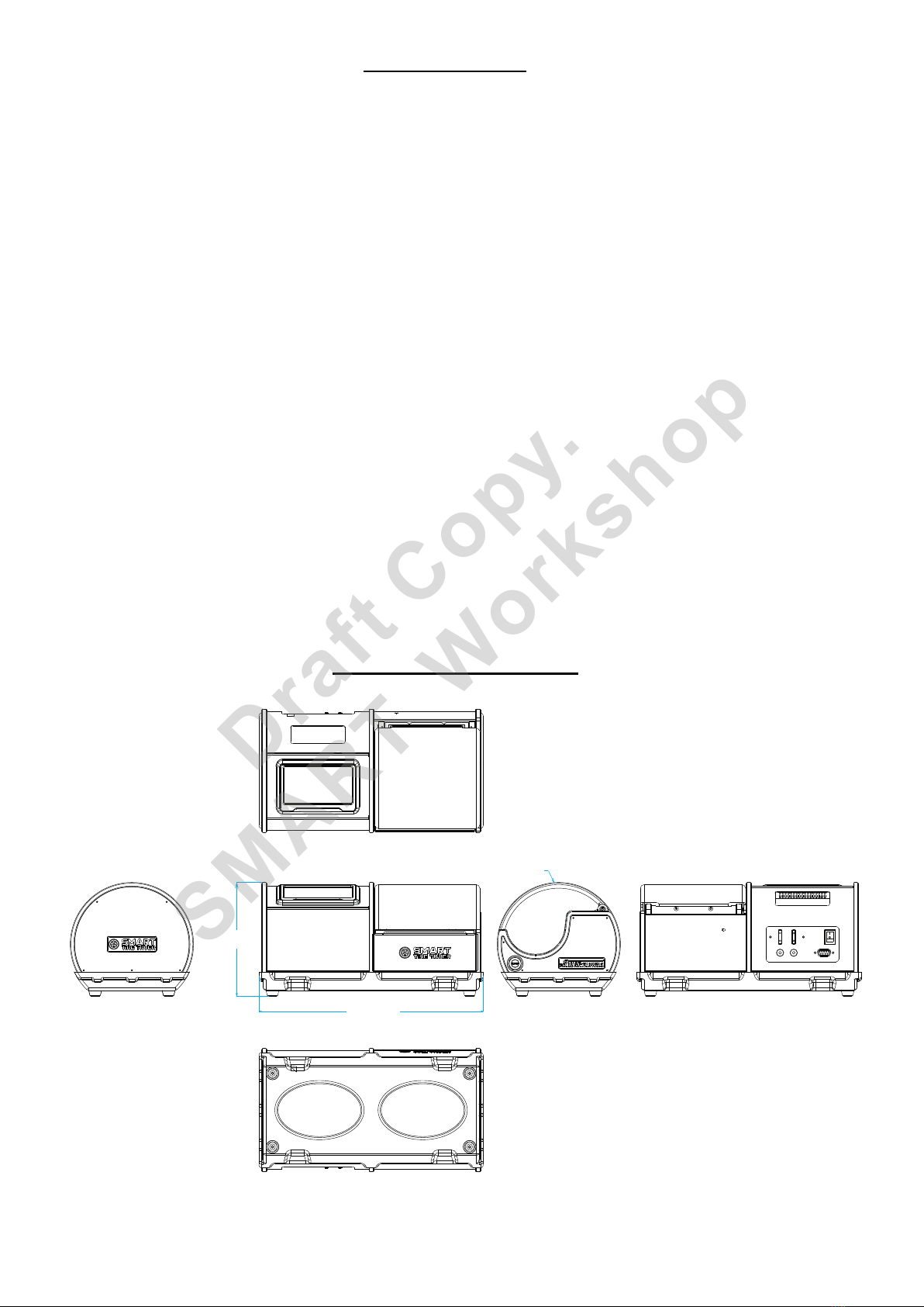
Product Dimension
Main features
L=315.0mm
W=175.0mm
H=160.0mm
Page 3
Draft Copy.
SMART Workshop

Page 4
1.
following operation guide to fix it.
When there is locking on X or Y axial block, please refer to the
1.1 Turn off the machine and remove the carbon fibre plate on the right side.
1.3 Turning the X axial until the Y axial near the hole on the back panel.
Note: Once X and Y axial is free, the machine will back to home position automatically
once you power on the machine. Calibration needed after this.
1.4
counterclockwise moves to the back).
Use 2.5 hex screwdriver turn the Y axial (Clockwise moves to the front and
1.2
counterclockwise moves to the right).
Use 2.5 hex screwdriver turn the X axial (Clockwise moves to the left and
Draft Copy.
SMART Workshop

Clean the dust on the dust cover frequently
2.
in each cut, if over the limit the infrared sensors will have serious
damage.
During Manual operation, the truing distance can’t more than 2mm
3.
dust cover movement.
Clean the dust on the dust cover frequently, avoid obstructing the
4. How to adjust the sensors cleaning block.
2.5mm
0mm
4.1 Use 2.5mm hex screwdriver to loosen up the screw as shown below.
4.2
(Cleaning block too close to the sensors will damage the sensors
during auto cleaning).
Adjust the cleaning block close to the sensors within the 1-1.5mm gap.
Page 5
Draft Copy.
SMART Workshop
Lase r Inju re hand
Caution
Equipment guidelines
Page 6
www. sma rt-wo rksh op.or g
Des ign an d Man ufac ture r by SMA RT-Wo rks hop
MODE L TR-32 3
ID03 102019 0101
PROD UCT ID No .
Turning ideas into reality
TIRE TRUER
G
E
R
N
E
C
M
Y
E
ST OP
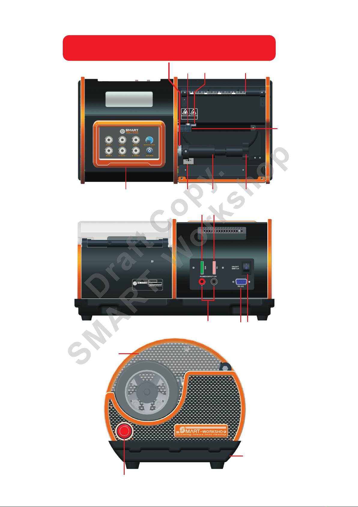
Touch Panel
Protective Cover
Spare Cutting Bit
Compartment
Sensors Cutting Bit Measuring Ruler
Sensors Cleaner
Locking Nut Wheel Adapter
Main Power Input 12V
Emergency Stop Switch
Container For Ground Rubber
CPU Board Fuses(3A)
Motor Fuses(30A)
Main Switch
RS 232
Draft Copy.
SMART Workshop
IMPORTANT - Don’t remove this stopper from the original position.
If accidentally moved, must be calibrated by alignment block.
Please refer to Service Manual for the calibration method.

Page 7
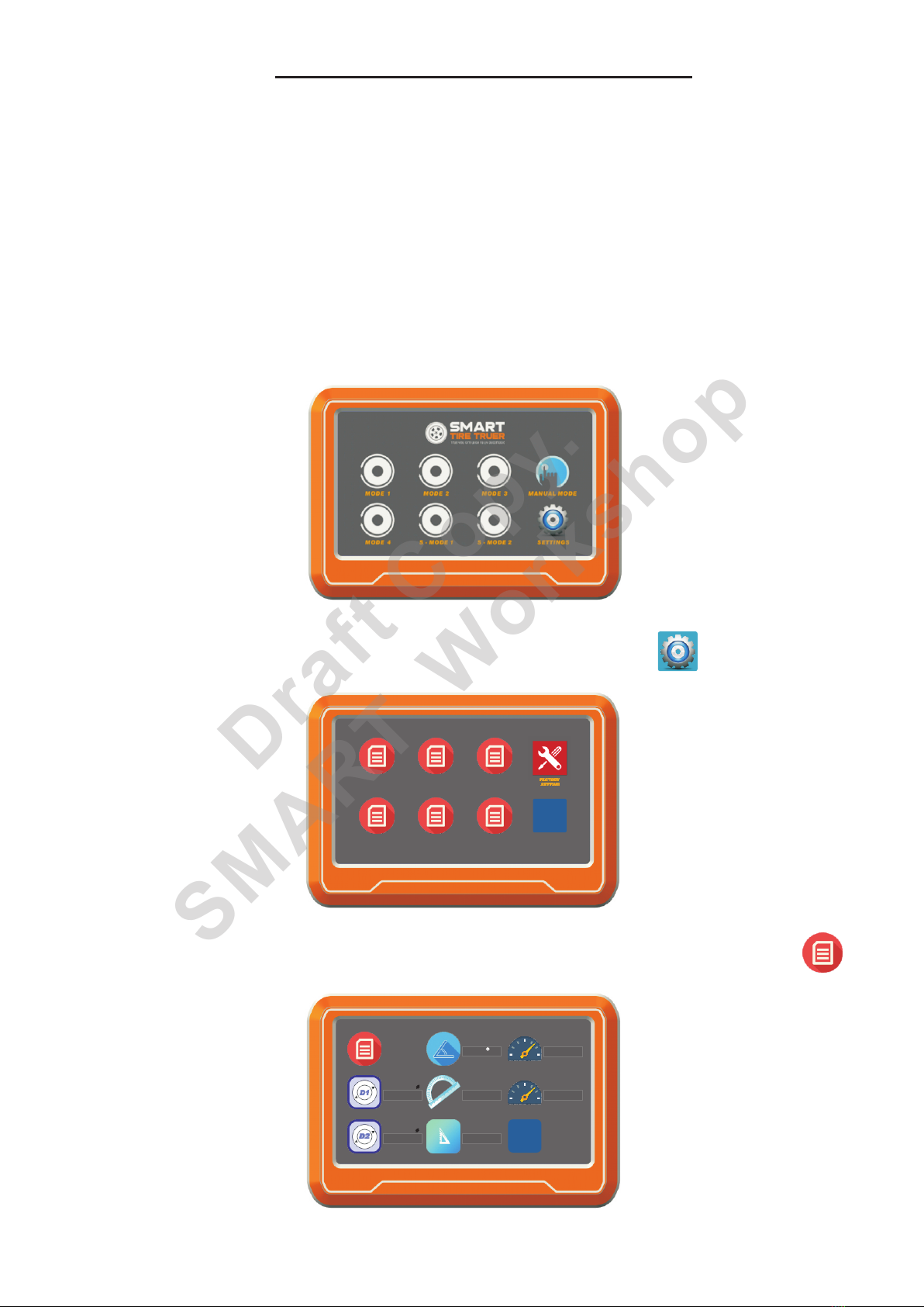
Main Menu
Parameter Setting Menu
Operating Menu
B. Mode 2
B. Setting Mode 2
B. Tire Original Diameter
B. Tire Original Diameter
A. Mode 1
A. Setting Mode 1
A. Setting Mode
*
*
A. Memory
C. Mode 3
C. Setting Mode 3
C. Tire Finish Diameter
D. Mode 4
D. Setting Mode 4
D. Camber
D. Tire Length
E. Round Edging
E. Camber
F. Round Edging
E. Special Mode 1
E. Special Mode 1
F. Tire Length
G. Speed
F. Special Mode 2
F. Special Mode 2
G. Speed 1
H. Traveling
G. Manual Mode
G. Factory Setting
H. Speed 2
I . Start
H. Setting
H. Exit
I . Exit
J
. Stop
K
. Exit
D E F H
A B C G
EXIT
MO DE 1 MODE 2 M OD E 3
MO DE 4 MO DE 2 MO DE 1
SE TTING S ET TING SE TT ING
SE TTING S PE CIA LSP ECIAL
SE TT ING
MO DE 1
EXIT
Ti re O ri ginal
mm
Tire Finish
mm
Ca mb er
Ro un d Ed ging
mm
mm
Sp eed 1
Sp eed 2
Tire Length
82.0
62.0 58.0
1.5 5
1
6.0
Memory 1
EXIT
Tire Finish
Tire Length
Tire Origin al
mmmm
82.0
62.0
0.0mm
mm
Ro und Edging
mm
Tr aveling
mm
Speed
Ca mber
1.5
6.0
9
0.0
Memory Setting Menu
Draft Copy.
SMART Workshop
A
A
A
D
B
B
C
B
D
E
H
E
F
G
H
J
C
G
I
K
G
D
C
E
F
F
I
H
C. Tire Finish Diameter
B. Mode 2
EXIT
MO DE 1
MO DE 1
MO DE 2 MODE 3
MO DE 4 MO DE 2 MO DE 1
SE TTING
SE TT ING
SE TTING S ET TIN G
SE TTING S PE CIA LSP ECIAL
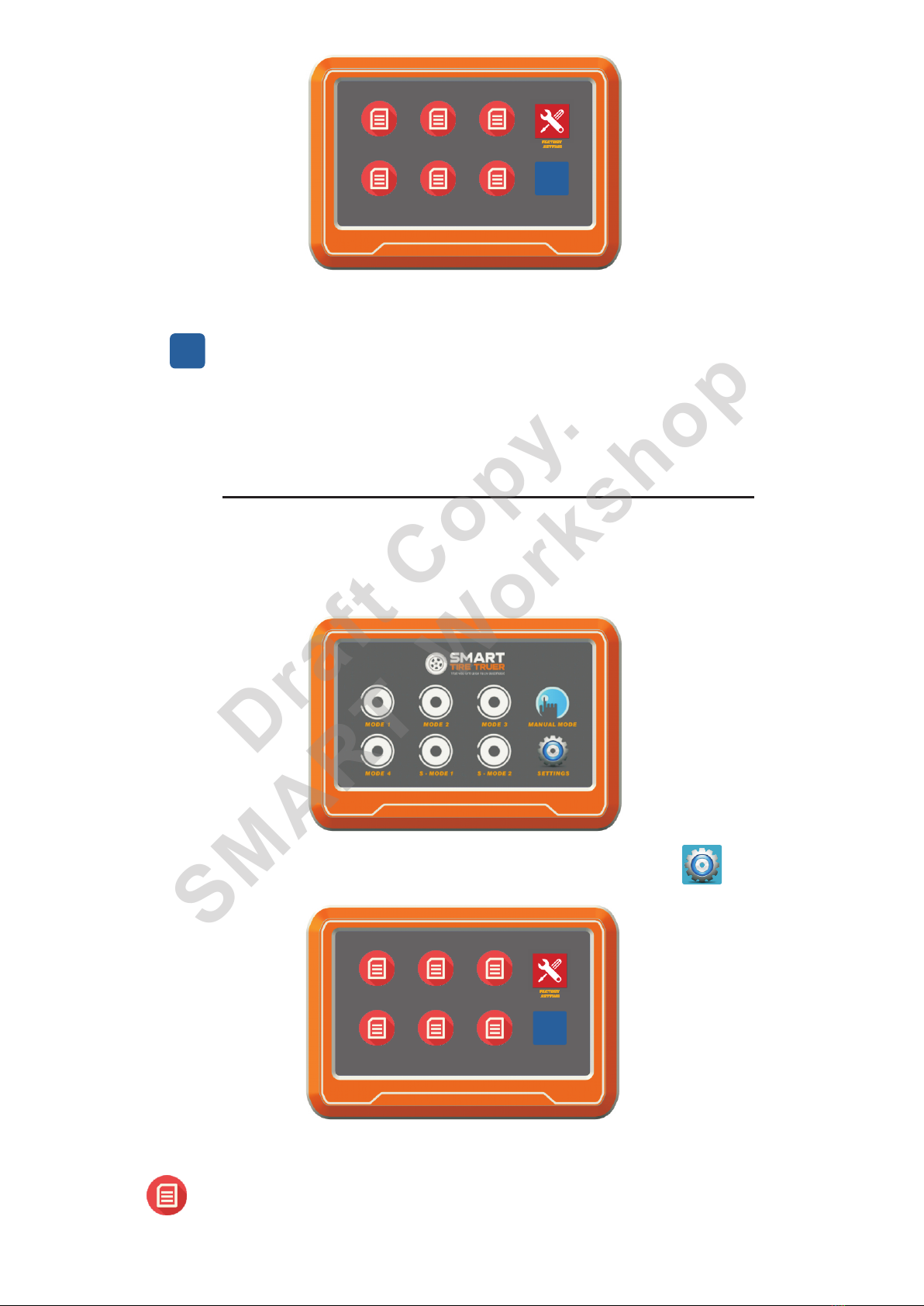
1 Press “Setting icon” enters Memory setting menu..
Mode 1 to 4 is designed for fully automatic feature, you only need to
measure the original outside diameter of the tire and key in all the para-
meters you prefer to use on the track. The measuring of tire original
diameter accuracy required is not high +/-1mm is acceptable (Low
accuracy will affect sensor detection).
We are not recommended to use Mode1-4 for those used tire or tire with
more than 3mm round edges. The large round edge radius will affect
sensors detection and accuracy of tire width measurement. But you can
use our Special Mode1-2 to fulfil this job (Please refer to Special Mode
setting instructions).
2 Press “Setting Mode Icon” enters to Parameter Setting Menu..
Mode1-4 Setting Instructions
SETTI NGS
SE TT ING
MO DE 1
EXIT
Ti re O ri ginal
mm
Tire Finish
mm
Ca mb er
Ro un d Ed ging
mm
mm
Sp eed 1
Sp eed 2
Tire Length
82.0
62.0 58.0
1.5 5
1
6.0
Page 8
Draft Copy.
SMART Workshop
*

Remark:
We provide two types of the key in methods to key in the tire original diameter.
1. “Manual Key In” Direct key in the number of tire original diameter from
screen.
2. “Manual Detection” Detect the tire original diameter by cutting bit under
manual operating. Only one method requested.
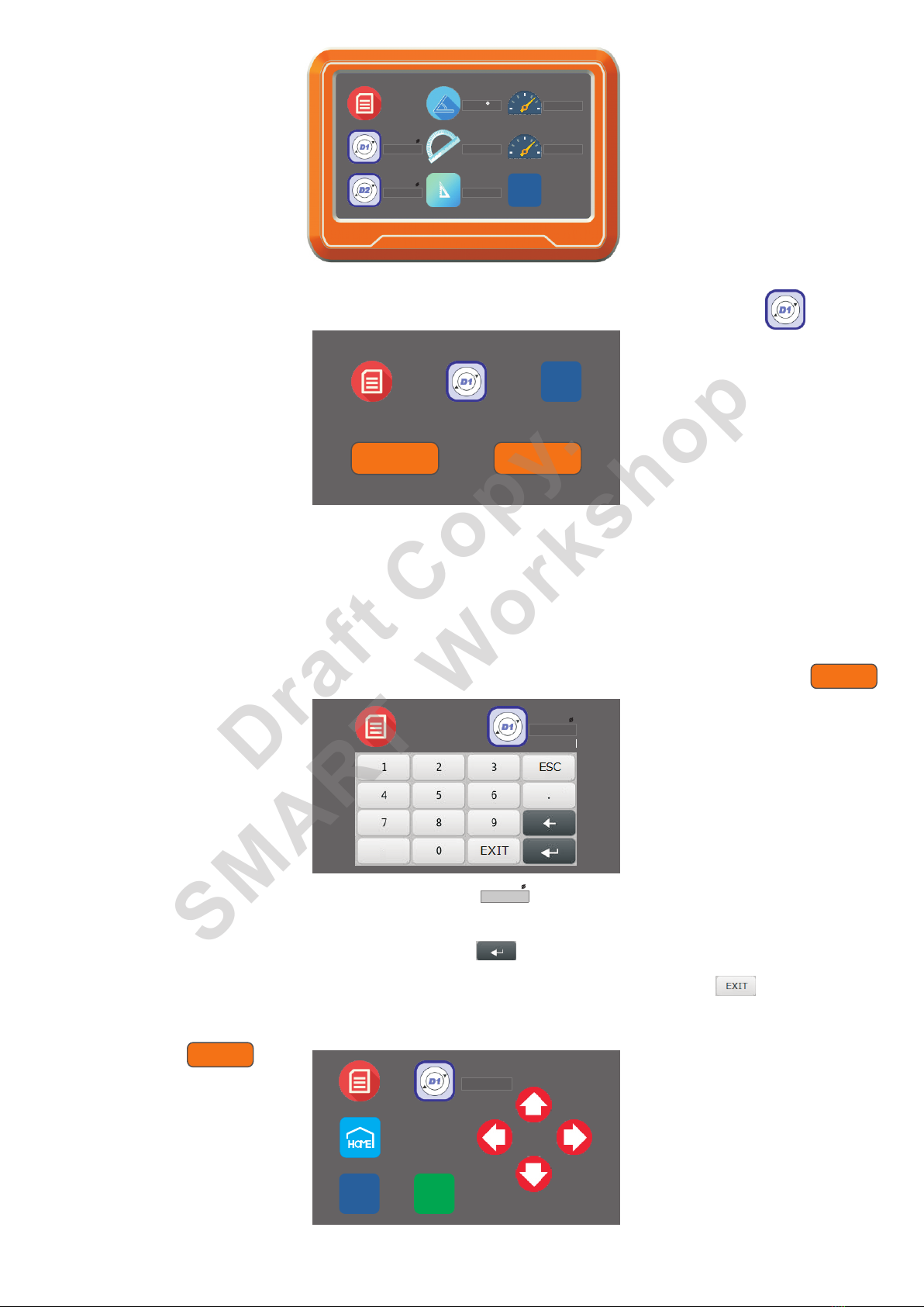
2.1.1 Press “Manual key in Icon” enters to D1 manual key in menu.
2.1.2 Press “Manual Detection Icon” enters to D1 manual detection menu.
2. .1 1.1 Press “D1 flash cursor Icon”.
2. .1
position.
1.2 Press “Home Icon” wait for the truer cutting bit block return to home
2. .3 1.2 Press “Exit Icon” back to the Parameter Setting Menu.
2. .2
surface and complete with “Enter Icon”.
1.2 Use “Direction Arrow Icon” to move the truer cutting bit near to tire
2. .3 1.1 Press “Exit Icon” back to the Parameter Setting Menu.
Move the Cutting bit near to tire surface Move Cutting bit close to the surface of the tire
2. .2
and complete with “Enter Icon”.
1.1 Key in the number of tire original diameter from screen keypad
Memory 1 Tire Origin al
Tire Origin al
mm
mm
Tire Origin al R
mm
EXIT
EXIT
SAVE
HOME
HO ME
SE TTING
MO DE 1
2.1 Press “D1 icon” enters to original diameter setting menu.
SE TTING
MO DE 1
Manual
Key In
Manual
Key In
Manual
Detection
Manual
Detection
EXIT
Page 9
X movement
Y movement
Draft Copy.
SMART Workshop
Page 10
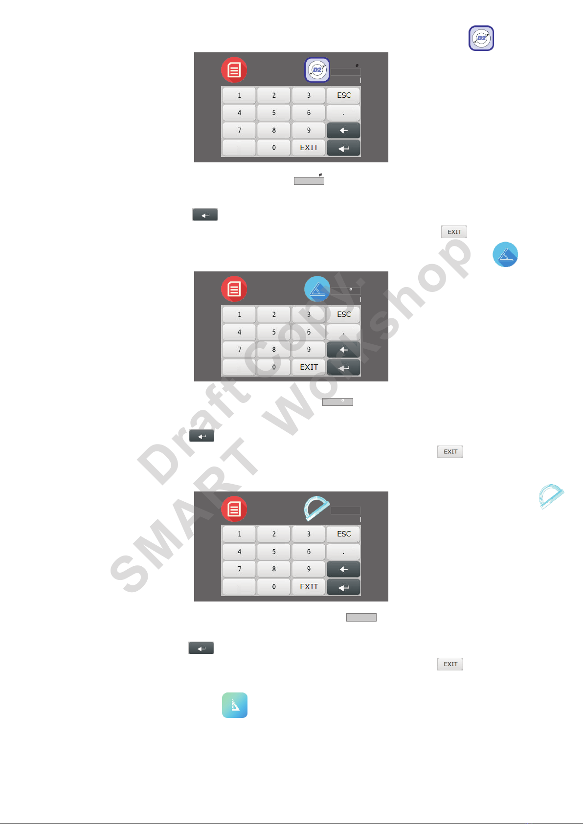
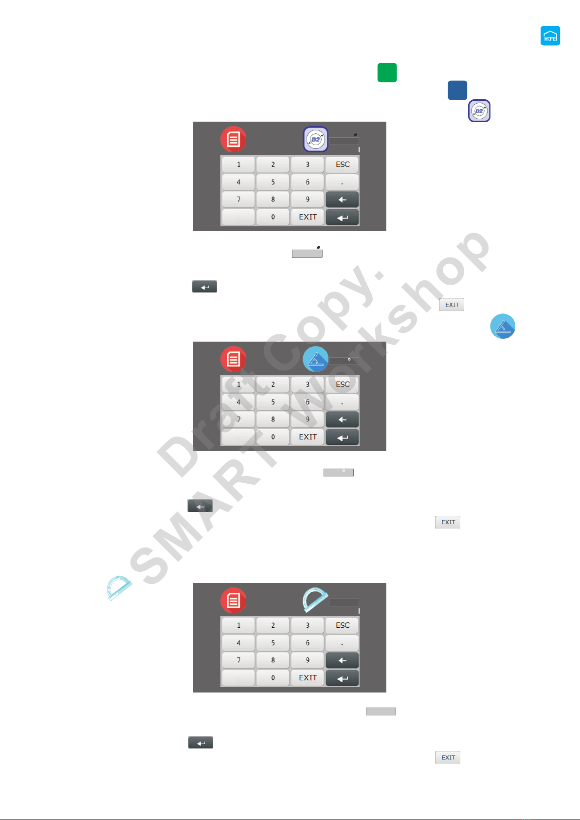
2 2 Press “D2 Icon” enters to truing diameter setting menu. .
2 3 Press “Camber Icon” enters to camber angle setting menu..
2 4 Press “Round Edging Icon” enters to Round edge radius setting menu..
2 5 “Tire Length” setting will auto detected by machine, no parameter .
needed for Mode1-4.
2 2.1 Press “D2 flashing cursor Icon”..
2 3.1 Press “Camber cursor Icon”.. flashing
2 4.1 Press “Round Edging flash cursor Icon”..
2 3.2 Key in the number of camber angle from screen keypad and complete
with “Enter Icon”.
.
2 4.2 Key in the number of round edge radius from screen keypad and complete
with “Enter Icon”.
.
2 3.3 Press “Exit Icon” back to the Parameter Setting Menu..
2 4.3 Press “Exit Icon” back to the Parameter Setting Menu..
2 2.2 Key in the number of truing diameter from screen keypad and complete
with “Enter Icon”.
.
2 2.3 Press “Exit Icon” back to the Parameter Setting Menu..
Memory 1 Tire Finis h
Tire Finis h
mm
mm
Memory 1 Ca mber
Ca mber
Memory 1 Ro und E dging
Ro und E dging
mm
mm
Tire Length
Draft Copy.
SMART Workshop

2 6.1 Press “Speed 1 cursor Icon”.. flashing
2 7.1 Press “Speed 2 cursor Icon”.. flashing
2 7.3 Press “Exit Icon” back to Parameter Setting Menu..
2 7.2 Key in the number of traveling Speed from screen keypad and
complete with “Enter Icon”.
.
2 6.2 Key in the number of traveling Speed level from screen keypad and
complete with “Enter Icon”.
.
2 6.3 Press “Exit Icon” back to Parameter Setting Menu..
2 6 Press “Speed 1 Icon” enters to surface truing traveling speed level
setting menu.
.
2 7 Press “Speed 2 Icon” enters to round edge truing traveling speed
level setting menu.
.
Sp eed
Sp eed 1
Sp eed 2
Speed 1
Speed 1
Memory 1
Sp eed
Speed 2
Speed 2
Memory 1
Page 11
SE TT ING
MO DE 1
EXIT
Ti re O ri ginal
mm
Tire Finish
mm
Ca mb er
Ro un d Ed ging
mm
mm
Sp eed 1
Sp eed 2
Tire Length
82.0
62.0 58.0
1.5 5
1
6.0
2 8 Press “EXIT Icon” on Parameter Setting Menu, the parameter's entire
.
saved and return to Memory Setting Menu. EXIT
Draft Copy.
SMART Workshop
Page 12
*
2 9 Press “EXIT Icon” on the Memory Setting Menu and return to Main
.
Special mode is designed for those tire round edge is too large, it will
affect the sensors detection. Because of this, we add a manual detection
function for the width of the tire.
Menu.
EXIT
EXIT
MO DE 1 MODE 2 M OD E 3
MO DE 4 MO DE 2 MO DE 1
SE TTING S ET TING SE TT ING
SE TTING S PE CIA LSP ECIAL
Special Mode1-2 Setting Instructions
EXIT
MO DE 1 MODE 2 M OD E 3
MO DE 4 MO DE 2 MO DE 1
SE TTING S ET TING SE TT ING
SE TTING S PE CIA LSP ECIAL
MO DE 1
SP EC IA L
1 Press “Setting Icon” enters to Memory setting menu..
2 Press “Setting SPECIAL Mode Icon” enters to Parameter Setting .
Menu.
SETTI NGS
Draft Copy.
SMART Workshop
SP EC IAL
MO DE 1
EXIT
Ti re O ri ginal
mm
Tire Finish
mm
Ca mb er
Ro un d Ed ging
mm
mm
Sp eed 1
Sp eed 2
Tire Length
82.0
62.0 58.0
1.5 5
1
6.0
Remark:
We provide two types of the key in methods to key in the tire original diameter.
1. “Manual Key In” Direct key in the number of tire original diameter from
screen.
2. “Manual Detection” Detect the tire original diameter by cutting bit under
manual operating. Only one method requested.
2.1.1 Press “Manual key in Icon” enters to D1 manual key in menu.
2.1.2 Press “Manual Detection Icon” enters to D1 manual detection
2. .1 flashing 1.1 Press “D1 cursor Icon”.
2. .3 1.1 Press “Exit Icon” back to the Parameter Setting Menu.
2. .2
and complete with “Enter Icon”.
1.1 Key in the number of tire original diameter from screen keypad
2.1 Press “D1 Icon” enters to original diameter setting menu.
Manual
Key In
SP ECIAL
MO DE 1
Manual
Key In
Manual
Detection
EXIT
SPECIAL
MODE 1
SPECIAL
MODE 1
Tire Origin al
Tire Origin al
mm
mm
Manual
Detection
Tire Origin al R
mm
EXIT SAVE
HOME
SP ECIAL
MO DE 1
Menu.
Page 13
Draft Copy.
SMART Workshop
2. .1 1.2 Press “Home Icon” the cutting bit block will return to home position.
2. .3 1.2 Press “Exit Icon” back to the Parameter Setting Menu.
2. .2
tire surface and complete with “Save Icon”.
1.2 Press “Direction Arrow Icon” move the truer cutting bit near to
2 2 Press “D2 Icon” enters to truing diameter setting menu. .
2 3 Press “Camber Icon” enters to camber angle setting menu..
2 2.1 Press “D2 cursor Icon”.. flashing
2 3.1 Press “Camber cursor Icon”.. flashing
2 3.2 Key in the number of camber angle from screen keypad and complete
with “Enter Icon”.
.
2 3.3 Press “Exit Icon” back to the Parameter Setting Menu..
2 2.2 Key in the number of truing diameter from screen keypad and complete
with “Enter Icon”.
.
2 2.3 Press “Exit Icon” back to the Parameter Setting Menu..
2 4 Press “Round Edging Icon” enters to Round edge radius setting.
2 4.1 Press “Round Edging cursor Icon”.. flashing
2 4.2 Key in the number of round edge radius from screen keypad and complete
with “Enter Icon”.
.
2 4.3 Press “Exit Icon” back to the Parameter Setting Menu..
Tire Finis h
Tire Finis h
mm
mm
SPECIAL
MODE 1
Ca mber
Ca mber
SPECIAL
MODE 1
Ro und E dging
Ro und E dging
mm
mm
SPECIAL
MODE 1
Menu.
Page 14
HO ME
SAVE
EXIT
Draft Copy.
SMART Workshop

Page 15
2 5 Press “Tire Length Icon” enters to Tire Length setting menu..
Tire Length
Tire Length
EXIT
EXIT
ORIGI N
OR IGI N
mm mm
Start E nd
2 5.1 Press “Home Icon” wait for the cutting bit block return to the home
position.
.
Starting point
Ending point
2 5.3 Use “Direction Arrow Icon” to move the left sides of the cutting bits
to the right edge of the tire to get the ending point and complete with
“Save Icon”.
.
2 5.4 Press “Exit icon” back to the parameter setting menu..
2 5.2 Use “Direction Arrow Icon” to move the right sides of the cutting bits
to the left edge of the tire to get the starting point and complete with
“Save Icon”.
.
2 6.1 Press “Speed 1 cursor Icon”.. flashing
2 6 Press “Speed 1 Icon” enters to surface truing traveling speed level
setting menu.
.
Sp eed
Sp eed 1
Speed 1
Speed 1
SPECIAL
MODE 1
Draft Copy.
SMART Workshop

Page 16
SP EC IAL
MO DE 1
EXIT
Ti re O ri ginal
mm
Tire Finish
mm
Ca mb er
Ro un d Ed ging
mm
mm
Sp eed 1
Sp eed 2
Tire Length
82.0
62.0 58.0
1.5 5
1
6.0
2 8 Press “EXIT Icon”on Parameter Setting Menu, the parameters entire
.
saved and return to Memory Setting Menu. EXIT
2 9 Press “EXIT Icon” on the Memory Setting Menu and return to Main
.
Menu.
EXIT
EXIT
MO DE 1 MODE 2 M OD E 3
MO DE 4 MO DE 2 MO DE 1
SE TTING S ET TING SE TT ING
SE TTING S PE CIA LSP ECIAL
2 7.1 Press “Speed 2 cursor Icon”.. flashing
2 7.3 Press “Exit Icon” back to the Parameter Setting Menu..
2 7.2 Key in the number of traveling Speed from screen keypad and
complete with “Enter Icon”.
.
2 7 Press “Speed 2 Icon” enters round edge truing traveling speed
setting menu.
. to
Sp eed 2
Sp eed
Speed 2
Speed 2
SPECIAL
MODE 1
2 6.2 Key in the number of traveling Speed level from screen keypad and
complete with “Enter Icon”.
.
2 6.3 Press “Exit Icon” back to the Parameter Setting Menu..
Draft Copy.
SMART Workshop

Page 17
Memory 1
EXIT
Tire Finis h
Tire Length
Tire Origin al
mmmm
82.0
62.0
0.0mm
mm
Ro und Edging
mm
Tr aveling
mm
Speed
Ca mber
1.5
6.0
9
0.0
2 Press “Mode Icon” which you need to use enters to Operating Menu..
3 Press “Tire Length Icon” enters to auto tire length detection..
(This step is just for checking the tire length, you can skip this step
if you’re confident with your tires ).
4 Press “Start Icon” to start truing tire..
3 1 The sensors will move to detect tire length and detected length will show
on screen once completed.
.
4 1 Sensors will detect the tire length automatically and show on the screen. .
4 2 Truing motor will turn on automatically..
4 3 Truing the tire diameter and camber automatically..
4 4 Truing the left and right round edge automatically..
4 5 The cutting bit block will go back to the home position after the truing
process completed.
.
4 6 Remove the tire from wheel adapter..
4 7 Press “Start Icon” to redo tire truing with the same program..
4 8 Press “EXIT Icon” back to Main Menu. .
During truing operating you can “Press Stop Icon” to stop the machine or
press the Emergency button cut off the power.
Please check all the setting parameter is correct and make sure the tire
installed properly before you proceed to start. The length of the tire will
show once the detection completed.
1 Press “Mode Icon” enters to Operating Menu.
.
Auto Mode Operation Instructions
MODE 1
Draft Copy.
SMART Workshop

Manual Mode Operation Instructions
1 Press “Manual Mode Icon” enters to Manual Operating Menu.
.
2 Press “Home Icon” machine will back to home position automatically.
.
3 Press “Speed Icon” enters to Speed Setting Menu.
.
4 Press “Direction Arrow Icon” to move the truer cutting bit as you like.
.
MA NUAL MO DE
EXIT
EXIT
X:
X:
mm
mm
mm
mm
Y:
Y:
ON
ON
Sp ee d
Sp eed
Sp eed
MA NU AL MODE
MANUA L MODE
HO ME
HOME
HO ME
0.0
0.0
8
8
35.0
35.0
3 1 Key in the number of speed levels from screen keypad and complete with
“Enter Icon”.
.
3 2 Press “EXIT Icon” return to Manual Operating Menu..
MANUA L MODE
Speed
Speed
Page 18
Draft Copy.
SMART Workshop
Table of contents
Popular Tyre Changer manuals by other brands


Corghi
Corghi A 9824 TI Operator's manual

Weber
Weber Expert Series manual

HENNESSY INDUSTRIES
HENNESSY INDUSTRIES Coats Rim Clamp X-Model Series instructions

HENNESSY INDUSTRIES
HENNESSY INDUSTRIES Coats CHD-4730-4730W Operating and maintenance instructions

Hofmann
Hofmann monty 3550 Operation instructions, Spare parts list

Corghi
Corghi A 222 Operator's manual

ATLAS PLATINUM
ATLAS PLATINUM PTC 300 Use and maintenance instruction manual

Mondolfo Ferro
Mondolfo Ferro Startline S 524 Operator's manual

Accu-Turn
Accu-Turn 526T instruction manual

Glomstad Motor
Glomstad Motor GM-U221 PRO Use and maintenance manual

Fasep
Fasep BALATRON 331.G3 user manual

ATH-Heinl
ATH-Heinl 7226 operating instructions