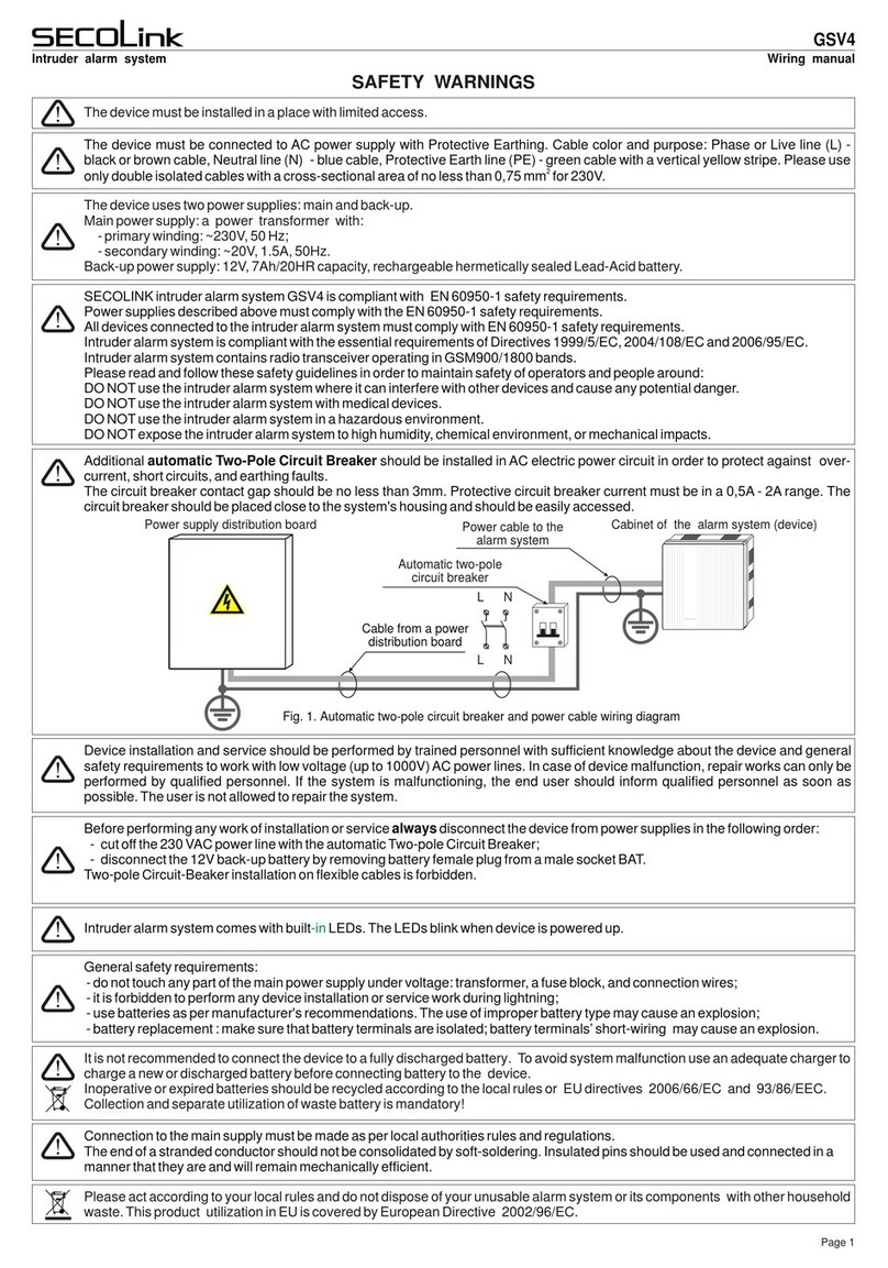
SmartCell SC-13-1100-0001-99 User manual

©2021 EMS Ltd. All rights reserved. TSD127-0001-99 (Issue 1) 05/05/2021 AJM
FIRE
FAULT
POWER
FUNCTION 1
FUNCTION 2
1
2
3
4
Intelligent Wireless Zone Monitor
Wireless Control Panel
Installation Guide

©2021 EMS Ltd. All rights reserved. Page 2 of 14 TSD127-0001-99 (Issue 1) 05/05/2021 AJM
Part No Product description
SC-13-1100-0001-99
SC-13-2100-0001-99
Intelligent Wireless Zone Monitor (230 VAC Version)
Intelligent Wireless Zone Monitor (24 VDC Version)
1 Introduction
The Intelligent Wireless Zone Monitor (WZM) allows for 16 wireless devices to be added to
Conventional or Addressable fire systems.
Typical addressable fire system connection
Typical conventional fire system connection
SmartCell WZM
Example Conventional panel
Up to 16x SmartCell
wireless devices
Zone 1
Sound 1
Zone 2
Sound 2
DUALINPUT/OUTPUT DEVICE
LOGONPOINT
SmartCell WZM
Example addressable panel
DUALINPUT/OUTPUT DEVICE
LOGONPOINT
Up to 16x SmartCell
wireless devices
F1 F2
F3 F4

©2021 EMS Ltd. All rights reserved. Page 3 of 14 TSD127-0001-99 (Issue 1) 05/05/2021 AJM
2 Pre installation
For optimum wireless performance, the following must be observed:
Ensure the WZM is not installed within 2 m of other wireless or electrical equipment.
Ensure the WZM is not installed within 0.6 m of any metal work.
2 m
0.6 m
3 Mounting location guidelines
Never site the WZM near metal work or
electrical equipment
The procedures outlined in this installation guide must be carefully followed.
The installation must conform to applicable local installation codes and should only be
installed by a fully trained competent person.
!
The WZM includes components which are susceptible to damage from Electro Static
Discharge (ESD). These components could be permanently damaged through routine
handling, if precautions are not observed. Where handling is required, adequate
earthing precautions should be taken, e.g. use an earthed wrist strap.
To ensure correct operation, products must be used within the specified environmental
operating conditions.

©2021 EMS Ltd. All rights reserved. Page 4 of 14 TSD127-0001-99 (Issue 1) 05/05/2021 AJM
Unclip the side panels.
Loosen the two screws.
Disconnect the ribbon cable.
Turn and release the door hinges.
Open the door.
5 Optional door removal
230 VAC variant shown
1. 3.2. 4.
Foradditional information refer to TSD032
EN54-4UNIVERSAL PSU
SC-60-1000
INPUT:220-240VAC, 50Hz, 0.3A
OUTPUT:5.0-8.5VDC, 0.8A MAX
STATUS
FAU LT
MAINS/ CHARGER FAIL
BATTERYLOW
BATTERYFAIL
START
INPUT
L N
Foradditional information refer to TSD042
0359-CPR-00267
15 0905
SLIDETO
REMOVE
EOL
(+) (-) (+) (+) (-) (+) (-) (+) (-) (+) (+) (-)
SOUNDERA
L1 L1 L2 EOL ALARM L1 L1 L2
IN OUT RES IN OUT
ZONE
A B A B NC C NO NC C NO
FIRE
INPUT2
INPUT1 FAULT
FAULT
ACTIVE
FAULT
ACTIVE
A
B
C
D
4 Open the WZM


©2021 EMS Ltd. All rights reserved. Page 6 of 14 TSD127-0001-99 (Issue 1) 05/05/2021 AJM
8 Wiring to an addressable fire system
Wire the inputs as shown below, using the resistor pack provided.
If an input is not being used, leave the 20 kΩ resistor as factory fitted.
Both outputs are voltage free and rated 30 V @ 1 A.
The maximum cable length to connected devices is 10 m.
FOOTNOTES
*
†
Optional cabling, required only when the following SmartCell devices are added to the WZM;
detectors, call points and I/O units (I/O units when set to ‘Off When Reset’) - see the SmartCell
WZM Programming Guide (MK067) for more details on this feature.
Wiring can be normally open or normally closed operation as required.
SKIP THIS STEP IF CONNECTING TO A CONVENTIONAL FIRE SYSTEM.
BAT
ENABLE
TAMPER
RESET
AERIALA AERIALB
ATTENTION
ELECTROSTATIC
SENSITIVEDEVICE
RS232
EN54-4UNIVERSAL PSU
SC-60-1000
INPUT:220-240VAC, 50Hz, 0.3A
OUTPUT:5.0-8.5VDC, 0.8A MAX
STATUS
FAULT
MAINS/ CHARGER FAIL
BATTERYLOW
BATTERYFAIL
START
INPUT
L N
Foradditional information refer to TSD042
0359-CPR-00267
15
0905
SLIDETO
REMOVE
EOL
(+) (-) (+)(+) (-) (+) (-) (+) (-) (+) (+) (-)
SOUNDERA
L1 L1 L2 EOL ALARM L1 L1 L2
IN OUT RES IN OUT
ZONE
A B A B NC C NO NC C NO
FIRE
INPUT2
INPUT1 FAULT
FAULT
ACTIVE
FAULT
ACTIVE
A
B
C
D
230 VAC variant shown
NC C NO NC C NO
FIRE FAULT
A B
INPUT1
FAULT
ACTIVE
A B
INPUT2
FAULT
ACTIVE
FAULT INPUT
FIRE INPUT
NO C
FIRE OUTPUT 2
(to clear when
panel reset)
FIRE OUTPUT 1
(to clear when
panel silenced)
NO C NC NO C
Addressable fire system connections
NO C NC
*††
4k720k 4k7
20k

©2021 EMS Ltd. All rights reserved. Page 7 of 14 TSD127-0001-99 (Issue 1) 05/05/2021 AJM
The WZM must be connected to dedicated zone and sounder output.
The maximum cable length to connected devices is 10 m.
9 Wiring to a conventional fire system
SKIP THIS STEP IF CONNECTING TO AN ADDRESSABLE FIRE SYSTEM.
FOOTNOTES
*Ensure that the manufacturer’s specified end of line components and triggering resistors are
fitted. See the control panel’s instructions for more information.
BAT
ENABLE
TAMPER
RESET
AERIALA AERIALB
ATTENTION
ELECTROSTATIC
SENSITIVEDEVICE
RS232
EN54-4 UNIVERSALPSU
SC-60-1000
INPUT:220-240VAC, 50Hz, 0.3A
OUTPUT:5.0-8.5VDC, 0.8A MAX
STATUS
FAULT
MAINS/ CHARGER FAIL
BATTERYLOW
BATTERYFAIL
START
INPUT
L N
Foradditional information refer to TSD042
0359-CPR-00267
15
0905
SLIDETO
REMOVE
EOL
(+) (-) (+) (+) (-) (+) (-) (+) (-) (+) (+) (-)
SOUNDERA
L1 L1 L2 EOL ALARM L1 L1 L2
IN OUT RES IN OUT
ZONE
A B A B NC C NO NC C NO
FIRE
INPUT2
INPUT1 FAULT
FAULT
ACTIVE
FAULT
ACTIVE
A
B
C
D
R1 = Sounder circuit EOL
R2 = Zone circuit EOL
R3 = Alarm resistor
EOL
(+) (-) (+) (+) (-)
SOUNDER
ALARM
RES IN OUT
ZONE
L1 L1 L2
(+) (-) (+) (+) (-)
L1 L1 L2
EOL
(+) (-)
IN OUT
R3
R2
R1
ZoneSounder
+ -
Conventional fire system connections
+ -
*
*
*

©2021 EMS Ltd. All rights reserved. Page 8 of 14 TSD127-0001-99 (Issue 1) 05/05/2021 AJM
DC
POWER
0V V+
M
FAULT
OV V+
GEN
FAULT
A B
1
DC
POWER
0V V+
M
FAULT
OV V+
GEN
FAULT
A B
2
FAULT
NC C NO
RS232
FIRE
NC C NO
ACTIVE AC TIVE
FAULT FAULT
INPUT1 INPUT2
A B A B
DC
POWER
0V V+
M
FAU LT
A B
GEN
FAU LT
A B
1
POWER
0V V+
GEN
FAU LT
DC
POWER
0V V+
M
FAULT
A B
GEN
FAULT
A B
2
Power
Supply
Unit
(PSU)
EN54-4 UNIVERSAL PSU
SC-60-1000
INPUT: 220-240VAC, 50Hz, 0.3A
OUTPUT: 5.0-8.5VDC, 0.8A MAX
INPUT
L N
For additional information refer to TSD042
0359-CPR-00267
15
0905
Earth wire
Neutral wire
Live wire
10b Connection wiring (24 VDC version only)
SKIP IF INSTALLING A
230 VAC VARIANT.
Cable glands should be
used.
DO NOT leave excess
cable in the control
panel.
Two fault inputs are
also available (black
terminal blocks). They
are labeled M Fault
(mains fault) and Gen
Fault (general / battery
fault).
If a fault input (GEN
FAULT or M FAULT) is
not being used, leave
the link as factory
fitted.
10 Connection wiring (230 VAC version only)
24 VDC Dual
Output PSU
- +
24V Out
OUTPUT 1
N/O C N/C
Fault
- +
24V Out
N/O C N/C
Fault
OUTPUT 2
- +
24 V Out
OUTPUT 1
N/O C N/C
Fault
OUTPUT 2
- +
24 V Out
N/O C N/C
Fault
*
*
*Additional Mains
Fault Input available
220 to 240
VAC mains
input
SKIP IF INSTALLING A 24 VDC VARIANT.
A 220 to 240 VAC supply is required.
Use cable with a minimum cross section of 1.5 mm2
Connections must be made through a 20 mm cable entry
gland, incorporating cable clamp into the WZM.
An additional 15 mm of cable should be considered for the
earth connection to provide extra protection should the live
or neutral wires disengage.
This equipment relies on the building installation for
protection and requires a 5 A protection device which should
be labelled “Fire Alarm – Do Not Switch.
An all-pole mains switch should be provided as part of the building installation.

©2021 EMS Ltd. All rights reserved. Page 9 of 14 TSD127-0001-99 (Issue 1) 05/05/2021 AJM
Refit the door.
Ensure the ribbon cable and the doors hinges are securely fitted.
11 Refit the door
1. 3.2. 4.
BAT
ENABLE
TAMPER
RESET
AERIAL A AERIAL B
ATTENTION
ELECTROSTATIC
SENSITIVE DEVICE
RS232
EN54-4 UNIVERSAL PSU
SC-60-1000
INPUT: 220-240VAC, 50Hz, 0.3A
OUTPUT: 5.0-8.5VDC, 0.8A MAX
STATUS
FAULT
MAINS / CHARGER FAIL
BATTERY LOW
BATTERY FAIL
START
INPUT
L N
For additional information refer to TSD042
0359-CPR-00267
15
0905
SLIDE TO
REMOVE
EOL
(+) (-) (+) (+) (-) (+) (-) (+) (-) (+) (+) (-)
SOUNDER A
L1 L1 L2 EOL ALARM L1 L1 L2
IN OUT RES IN OUT
ZONE
A B A B NC C NO NC C NO
FIRE
INPUT2
INPUT1 FAU LT
FAU LT
ACTIVE
FAU LT
ACTIVE
A
B
C
D
Fit the WZM battery, observing correct polarity.
12 Fit back-up battery (230 VAC version only)
!Warning
Observe battery polarity!

©2021 EMS Ltd. All rights reserved. Page 10 of 14 TSD127-0001-99 (Issue 1) 05/05/2021 AJM
BAT
ENABLE
TAMPER
RESET
AERIAL A AERIAL B
ATTENTION
ELECTROSTATIC
SENSITIVE DEVICE
RS232
EN54-4 UNIVERSAL PSU
SC-60-1000
INPUT: 220-240VAC, 50Hz, 0.3A
OUTPUT: 5.0-8.5VDC, 0.8A MAX
STATUS
FAULT
MAINS / CHARGER FAIL
BATTERY LOW
BATTERY FAIL
START
INPUT
L N E
For additional information refer to TSD042
0359-CPR-00267
15
0905
SLIDE TO
REMOVE
EOL
(+) (-) (+) (+) (-) (+) (-) (+) (-) (+) (+) (-)
SOUNDER A
L1 L1 L2 EOL ALARM L1 L1 L2
IN OUT RES IN OUT
ZONE
A B A B NC C NO NC C NO
FIRE
INPUT2
INPUT1 FAU LT
FAU LT
ACTIVE
FAU LT
ACTIVE
A
B
C
D
13 Remove 3 V battery tab
The 3 V battery tab located on the back of the door must now be removed.
BAT
ENABLE
PULL
Reassemble the WZM.
14 Close the WZM

©2021 EMS Ltd. All rights reserved. Page 11 of 14 TSD127-0001-99 (Issue 1) 05/05/2021 AJM
Apply power to the WZM.
The green power LED will illuminate.
The other LEDs should be extinguished.
The screen should also display ‘System Normal’.
15 Apply power
NOTE: This product contains relays which when subjected to mechanical shock may cause
momentary transitions from the currently active state. The transitions will be less than 1 second
and any equipment connected must not respond to such momentary changes of the relay. This
product should be fixed to a stable and secure structure that is not subject to severe mechanical
shock.
POWER
SmartCell WZM
System Normal
01/01/00 Access
SmartCell WZM
System Normal
01/01/00 Access
The system can now be programmed.
Refer to the WZM programming Guide (MK067) for details of
compatible SmartCell devices and full programming
information.
16 Configuration

©2021 EMS Ltd. All rights reserved. Page 12 of 14 TSD127-0001-99 (Issue 1) 05/05/2021 AJM
Operating temperature -5 °C to +45 °C
Storage temperature 0 °C to 30 °C
Humidity 95 % non-condensing max.
Location Type A: for indoor use
IP rating IP30
Power requirements 230 VAC version: 220 to 240 VAC
24 VDC version: 19.2 to 28.8 VDC
Min/max electrical ratings 230 VAC version: 220 to 240 VAC, 50 Hz, 0.3 A
24 VDC version: N/A
Input / output fuse ratings 230 VAC version: Input - 3.15 A (non replaceable)
Output - 300 mA & 750 mA (resettable)
24 VDC version: F1 - 60 V 1.2 A (resettable)
F2 - 60 V 1.2 A (resettable)
Operating current 24 VDC version: 0.030 A (quiescent) and 0.042 A (alarm )
Battery backup 230 VAC version: 1 x 6V 4 Ah Yuasa NP4-6
24 VDC version: N/A
For information on routine battery changes, refer to the Universal PSU Instructions (TSD032)
Battery standby time 230 VAC version: 72 hours
24 VDC version: N/A
Maximum battery internal resistance 230 VAC version: 0.7 Ohms
24 VDC version: N/A
Max current drawn from the battery
by the pse with mains disconnected 230 VAC version: 5 mA (PSU), plus 100 mA from WZM
24 VDC version: N/A
Fire/fault relay ratings 1 A at 30 VDC
Maximum USB flash drive 128 GB, FAT32
Operating frequency 868 to 870 MHz
Output transmitter power 14 dBm
Signalling protocol X5
Maximum cable lengths Inputs 1 & 2 = 30 m
Dimensions (W x H x D) 275 x 220 x 80 mm
Specification

©2021 EMS Ltd. All rights reserved. Page 13 of 14 TSD127-0001-99 (Issue 1) 05/05/2021 AJM
Manufacturer EMS Ltd. Technology House, Herne Bay, Kent, CT6 8JZ
United Kingdom
Year of manufacture See devices serial number label
Certification
Certification body
CPR Certificate DOP 0359-CPR-00427
Approved to EN54-13:2005. Fire detection and fire alarm systems. Part 13:
Compatibility assessment of system components.
EN54-18:2005. Fire detection and fire alarm systems. Part 18:
Input/output devices.
EN54-25:2008. Incorporating corrigenda September 2010 and
March 2012. Fire detection and fire alarm systems. Part 25:
Components using radio links.
European Union directives EMS declares that the radio equipment type Intelligent WZM is in
compliance with Directive 2014/53/EU. The full text of the EU
declaration of conformity is available at the following internet
address: www.emsgroup.co.uk
2012/19/EU (WEEE directive): Products marked with this symbol
cannot be disposed of as unsorted municipal waste in the
European Union. For proper recycling, return this product to your
local supplier upon purchase of equivalent new equipment, or
dispose of it at designated collection points. For more
information see www.recyclethis.info
Dispose of your batteries in an environmentally friendly manner
according to your local regulations.
19
0905
Regulatory Information

©2021 EMS Ltd. All rights reserved. Page 14 of 14 TSD127-0001-99 (Issue 1) 05/05/2021 AJM
www.mysmartcell.co.uk
This manual suits for next models
1
Table of contents
