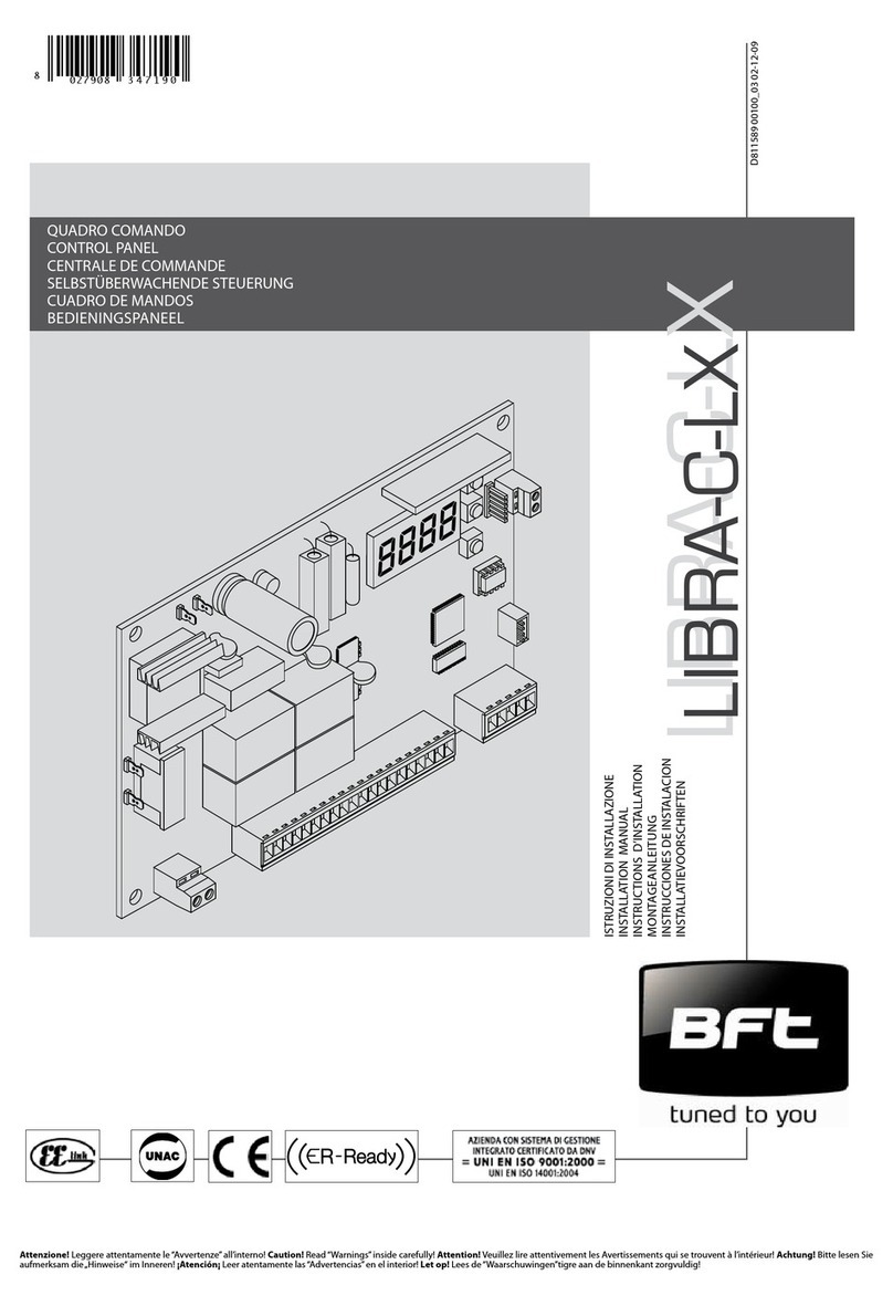
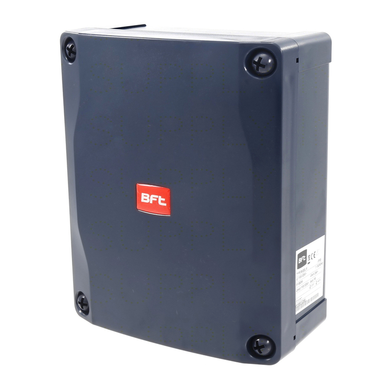
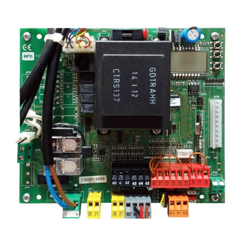
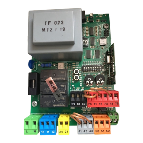
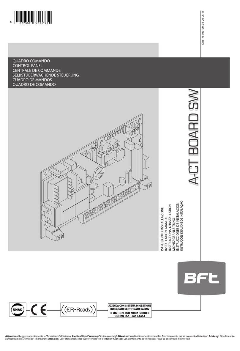
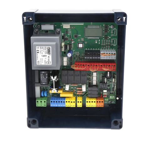
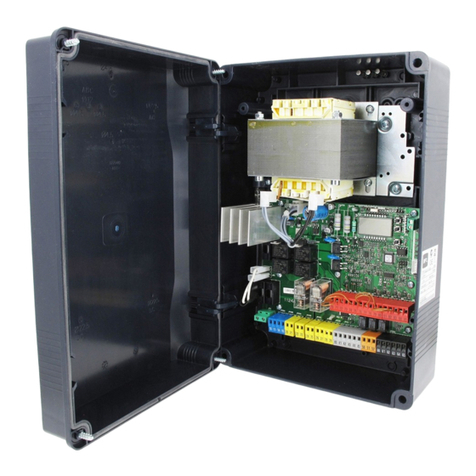
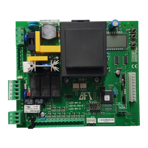
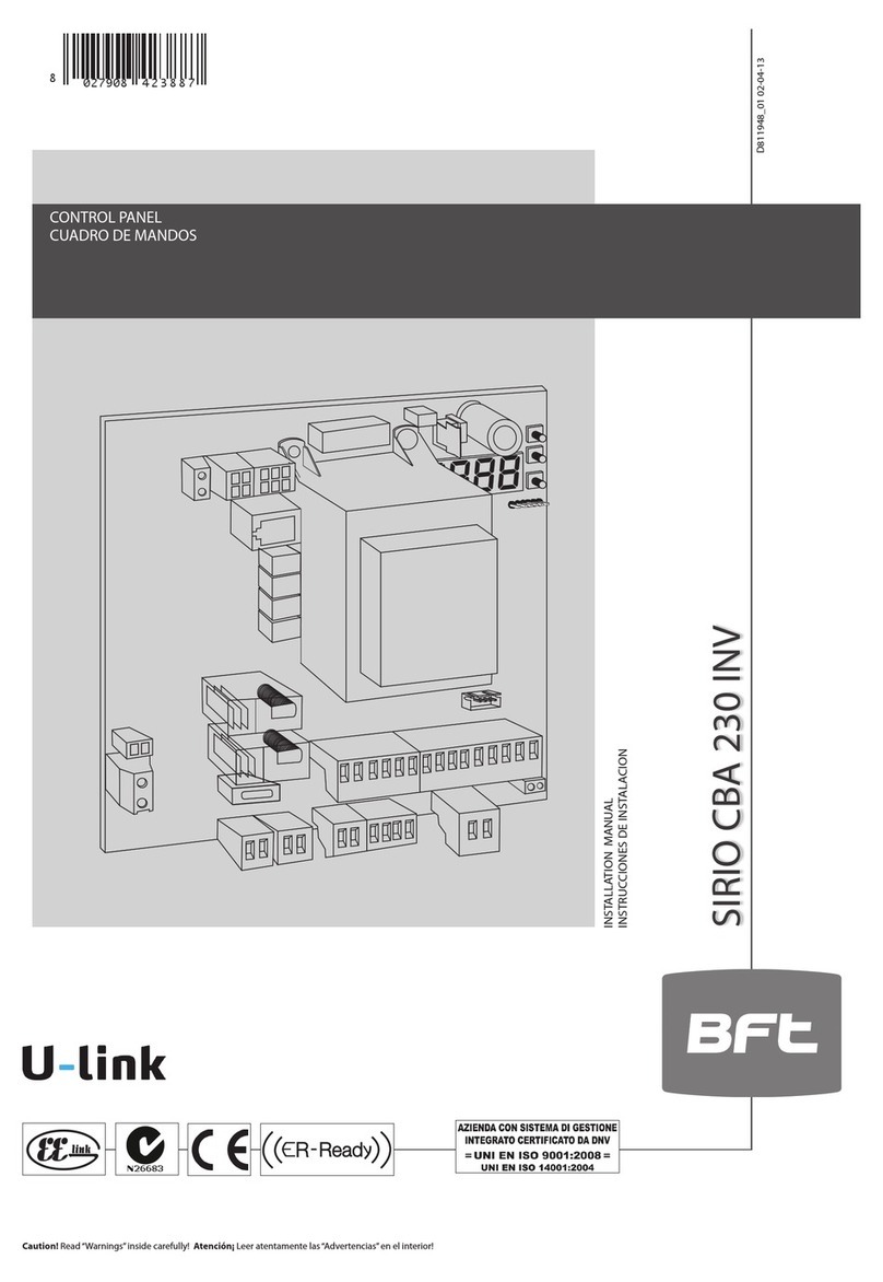
BFT THALIA User manual

THALIA
D814123 0AA00_01 13-12-19
I INSTALLATION MANUAL
THALIA
Attenzione! Leggere attentamente le“Avvertenze” all’interno! Caution! Read“Warnings”inside carefully! Attention! Veuillez lire attentivement les Avertissements qui se trouvent à l’intérieur! Achtung! Bitte lesen Sie
aufmerksam die„Hinweise“ im Inneren! ¡Atención¡ Leer atentamente las “Advertencias”en el interior! Let op! Lees de“Waarschuwingen”tigre aan de binnenkant zorgvuldig!
CONTROL PANEL

A
C
JP5 JP7
Y #
F2 3,15 AT
F1 1.25 AT(220-230V)
F1 2.5 AT (120V)
ANT.
ANT
SHIELD
24V
220-230V ~
*
S2
S1
S3
0,75
0,75
0,75
0,75
0,75
*
L N 10 11
LN
M1
220-230V ~
*
14 15 20 21 26 27 40 41 42 43 44 45 50 51 52 60 61 62 70 71 72 73 74 75
+
M2
24V
AUX 3
(MAX 24V 1A)
- REF SWE
+ REF SWE
SWC 1 / SW 1 / ENC1A
SWO 1 / SW 2 / ENC1B
SWC2 / ENC2A
SWO2 / ENC2B
24V -
24V +
24 VSafe+
COM
IC 1
IC 2
COM
SAFE 1
STOP
FAULT 1
SAFE 2
FAULT 2
-
+
-
NO
NO
NC
NC
NC
JP20
3x2,5 mm
2
3x2,5 mm
2
230V
(*)
24V
(*) 110V
26
AUX 3 ≠ 1 AUX 3 = 1
27
1
26 27 50 51
24 V~
SCA
220
+ +
S1
X1
OPEN
S1
X1
STOP
- -
S2
X1
CLOSE
S2
X1
STOP
OPEN
CLOSE
QUICK INSTALLATION
See motor specifications
ELI encoder activation
Other voltages available on request
Optional board connector
Palmtop programmer connector, Connecter
Display plus programming keys,
Power supply
Motor
Accessories power supply
Encoder/limit switch inputs
AUX
Safety devices
Commands
Antenna
TUBE ARRANGEMENT
D2D1
725150 70
24V ~
2
1TX1 2
1
RX1
4
5
3
SAFE 1 = 0 SAFE 1 = 1
725150 70
24V ~
Vsafe
7352
2
1TX1 2
1
RX1
4
5
3
2 - THALIA
D814123 0AA00_01

ENGLISH
A
C
JP5 JP7
Y #
F2 3,15 AT
F1 1.25 AT(220-230V)
F1 2.5 AT (120V)
ANT.
ANT
SHIELD
24V
220-230V ~
*
S2
S1
S3
0,75
0,75
0,75
0,75
0,75
*
L N 10 11
LN
M1
220-230V ~
*
14 15 20 21 26 27 40 41 42 43 44 45 50 51 52 60 61 62 70 71 72 73 74 75
+
M2
24V
AUX 3
(MAX 24V 1A)
- REF SWE
+ REF SWE
SWC 1 / SW 1 / ENC1A
SWO 1 / SW 2 / ENC1B
SWC2 / ENC2A
SWO2 / ENC2B
24V -
24V +
24 VSafe+
COM
IC 1
IC 2
COM
SAFE 1
STOP
FAULT 1
SAFE 2
FAULT 2
-
+
-
NO
NO
NC
NC
NC
JP20
3x2,5 mm
2
3x2,5 mm
2
230V
(*)
24V
(*) 110V
26
AUX 3 ≠ 1 AUX 3 = 1
27
1
26 27 50 51
24 V~
SCA
220
+ +
S1
X1
OPEN
S1
X1
STOP
- -
S2
X1
CLOSE
S2
X1
STOP
OPEN
CLOSE
ENGLISH
IT IS NECESSARY TO FOLLOW THIS SEQUENCE OF ADJUSTMENTS:
1 - Adjusting the limit switches
2 - Autoset
3 - Programming remote controls
4 - Setting of parameters/logic, where necessary
After each adjustment of the end stop position a new autoset is required.
After each modication of the motor type, a new autoset must be carried out
If the simplied menu is used:
- In GIUNO ULTRA BT A 20 GIUNO ULTRA BT A 50 - E5 BT A18 - E5 BT A12 motors: phase
1 (end stop adjustment) is included in the simplied menu.
- In other motors: phase 1 (end stop adjustment) must be carried out before activating
the simplied menu
D2D1
725150 70
24V ~
2
1TX1 2
1
RX1
4
5
3
SAFE 1 = 0 SAFE 1 = 1
725150 70
24V ~
Vsafe
7352
2
1TX1 2
1
RX1
4
5
3
Photocells not checked (Check every 6 months) Photocell checked
THALIA - 3
D814123 0AA00_01

ELI 250 BT
2
E
40 41 42 43 44 45
+ REF SWE
SWC 1
SWO 1
SWC2
SWO2
10 11
M1
14 15
+
M2
-
+
-
PHOBOS N BT
tipo otore - type de oteur - otorentyp - otor type - tipo otor:
1
tipo otore - type de oteur - otorentyp - otor type - tipo otor:
M1M2 M2M1 M2M2M1 M1
40 41 42 43 44 45
SW 1
10 11
M1
14 15
M2
+
-
+
-
SW 2
3
IGEA BT
tipo otore - type de oteur - otorentyp - otor type - tipo otor:
40 41 42 43 44 45
SW 1
10 11
M1
14 15
+
M2
-
+
-
SW 2
M2M1
123
SW 1
M1 +
M1-
123
SW 2
M2 +
M2-
M2M1
123
SW 1
M1 +
M1-
123
SW 2
M2 +
M2-
M1M2 M2M1
M2 M2 M1
M1
M1 M1 M2
M2
= 1 (ext)
open in other direct.
= 1 (ext)
open in other direct.
i
= 1 (ext)
open in other direct.
= 0 (int)
iopen in other direct.
= 0 (int)
open in other direct.
= 0 (int)
open in other direct.
ELI 250 BT
Maximum power 180W
Maximum cycle- continuous cycle
PHOBOS N BT
Maximum power n 40W
Cycle maximum
S3 13s-1-13s-1 x30
pause
IGEA BT
Maximum power 70W
Maximum cycle continuous cycle
change mot = 0
change mot =
change mot =
change mot =
change mot =
change mot = 0
4 - THALIA
D814123 0AA00_01

ENGLISH
SUB BT
tipo motore - type de moteur - motorentyp - motor type - tipo motor:
4
6
E
40 41 42 43 44 45
SW 1
SW 2
10 11
M1
14 15
-
M2
+
+
-
M1 M1 M2
M2 M2 M2 M1
M1
7
PHOBOS BT A / KUSTOS BT A tipo otore - type de oteur - otorentyp - otor type - tipo otor:
M1M2 M2M1 M2M2M1 M1
40 41 42 43 44 45
SW 1
10 11
M1
14 15
M2
+
-
+
-
SW 2
M2M1
123
SW 1
M1 +
M1-
123
SW 2
M2 +
M2-
White
Red
**Rosso
*Bianco
*Bianco
***Nero
***Nero
**Rosso
Black
SUB BT
Maximum power 90W
Maximum cycle S3 17s-1-17s-1 x21
pause
90 min.
LEAF MAX 400 kg
2 m
TYPE OF USE SEMIINTENSIVE Semi-intensive
= 0 (int)
open in other direct.
change mot =
= 1 (ext)
open in other direct.
change mot =
PHOBOS BT A KUSTOS BT A
Maximum power - 40W 40W
Maximum cycle
S3 13s-1-13s-1 x30
pause
90min.
S3 13s-1-13s-1 x30
pause
90min.
= 1 (ext)
open in other direct.
= 0 (int)
open in other direct.
change mot = change mot =
NONMANAGED MOTORS
THALIA - 5
D814123 0AA00_01

E
GIUNO ULTRA
tipo motore - type de moteur - motorentyp - motor type - tipo motor:
8
1
2
3
4
M1 +
M1 -
- REF SWE
SW 1
1
2
3
4
M2 +
M2 -
- REF SWE
SW 2
reg. fc. - l.sg adj - regl.fc - endsche inst
M1 M1 M2
M1 M2
M2 M2
M1 M1
M2
40 41 42 43 44 45
10 11
M1
14 15
M2
+
-
+
-
SW 1
- REF SWE
SW 2
1 2
GIUNO ULTRA BT A 20 GIUNO ULTRA BT A 50
Maximum power 90W 90W
Maximum cycle S3 10s-5-14s-5 x40
pausa -pause - pause pause -
pausa - pauze
90 min.
S3 10s-5-14s-5 x40
pausa -pause - pause pause - pausa -
pauze
90 min.
LEAF MAX. 150 kg 150 - 400 kg
2 m 5 - 2 m
TYPE OF USE SEMIINTENSIVE Semi-intensive
= 1 (ext)
open in other direct.
= 0 (int)
open in other direct.
change mot = change mot =
ATTENTION: with actuators with integrated locks, the permanently active slowdown to a value higher than 5 is mandatory.
6 - THALIA
D814123 0AA00_01

ENGLISH
E
40 41 42 43 44 45
SW 1
10 11
M1
14 15
M2
-
+
+
-
10
tipo otore - type de oteur - otorentyp - otor type - tipo otor:
SW 2
9
tipo otore - type de oteur - otorentyp - otor type - tipo otor:
40 41 42 43 44 45
+ REF SWE
SWC 1 *
SWO 1 *
SWC2 *
SWO2 *
blu***
rosso****
blu***
rosso****
10 11
M1
14 15
-
M2
+
-
+
M1 M2 M1 M2 M1 M2M1 M2
M2 M1 M2 M1
M2 M1
M2 M1
M2M1
123
SW 1
M1 -
M1+
123
SW 2
M2 -
M2+
inv.mot / change mot / inv.mot = 0
mot.tausch / inv.mot / inv.mot
inv.mot / change mot / inv.mot = 0
mot.tausch / inv.mot / inv.mot
inv.mot / change mot / inv.mot = 0
mot.tausch / inv.mot / inv.mot
inv.mot / change mot / inv.mot = 0
mot.tausch / inv.mot / inv.mot
inv.mot / change mot / inv.mot = 1
mot.tausch / inv.mot / inv.mot
inv.mot / change mot / inv.mot = 1
mot.tausch / inv.mot / inv.mot
inv.mot / change mot / inv.mot = 1
mot.tausch / inv.mot / inv.mot
inv.mot / change mot / inv.mot = 1
mot.tausch / inv.mot / inv.mot
SWC * / SWO **
SWO* / SWC**
VIRGO SMART BT A ( 3 wires )
VIRGO SMART BT A (5 wires)
= 0 (int)
open in other direct.
= 1 (ext)
open in other direct.
= 1 (ext)
open in other direct. :
= 0 (int)
open in other direct.
1= +Red ****
2= - Blu ***
3= SWO*/SWC**
4= SWC*/SWO**
5= +REF SWE
VIRGO SMART BT A
Maximum power 110W
Maximum cycle
20 cycles/h
* With reverse logic, opening direction = 000 (DIR=INT)
** With reverse logic, opening direction = 001 (DIR=ext)
*** Blu
**** Red
M1= VIRGO SMART BT A (Left) / M2= VIRGO SMART BT A SQ (Right)
M1= VIRGO SMART BT A (Right)/ M2= VIRGO SMART BT A SQ (Left)
ATTENTION: with actuators with integrated locks, the permanently active slowdown to a value higher than 5 is mandatory.
THALIA - 7
D814123 0AA00_01

E5 BT A18 E
40 41 42 43 44 45
- REF SWE
SW 1
10 11
M1
14 15
+
M2
-
+
-
SW 2
11
tipo otore - type de oteur - otorentyp - otor type - tipo otor:
E5 BT A12 12
tipo otore - type de oteur - otorentyp - otor type - tipo otor:
M2 M2 M1
M1
M1 M1 M2
M2
60
COM
1
2
3
4
M1 +
M1 -
COM
- REF SWE
SW 1
M1
5
1
2
3
4
M2 +
M2 -
COM
- REF SWE
SW 2
M2
5
E5 BT A18 E5 BT A12
Maximum power 40W 40W
Maximum cycle
20 cycles/h 100 cycles/h
LEAF MAX see the motor’s manual see the table below
Maximum cable length 30m 30m
= 1 (ext)
open in other direct.
= 0 (int)
open in other direct.
change mot = change mot =
E5 BT A12
ON pedestrian gates, adjust the speed so as to limit the energy of the leaf within a
maximum value of 1.69 Joule (as required by the EN16005 regulation).
Use the table to determine the minimum closing times between 90°and 10°.
Table with the leaf manoeuvre minimum times
Leaf width (mm)
)Leaf weight (kg)
50 60 70 80 90
750 mm 3,0 s 3,0 s 3,0 s 3,0 s 3,5 s
850 mm 3,0 s 3,0 s 3,5 s 3,5 s 4,0 s
1000 mm 3,5 s 3,5 s 4,0 s 4,0 s 4,5 s
1200 mm 4,0 s 4,5 s 4,5 s 5,0 s 5,5 s
The approaching phase (from 10° to the limit switch position) must take place in at least 1.5 s.
Example: if the leaf weighs 80 kg and has a width of 1000 mm, adjust the manoeuvre speed from 90° and 10° in at least 4.0 s.
For intermediate values, use the higher value: if the leaf weighs 75 kg consider a value of 80 kg, if its width is 1100 mm use a value of 1200 mm.
IMPORTANT: Low-energy operation is not considered a proper safety measure if the leaf is used by elderly, invalid, disabled people and children.
In this case, provide additional safety measures, according to the provisions of the legislation in force.
Select the correct
motor model
8 - THALIA
D814123 0AA00_01
ENGLISH
E5 BT A18 E
40 41 42 43 44 45
- REF SWE
SW 1
10 11
M1
14 15
+
M2
-
+
-
SW 2
11
tipo otore - type de oteur - otorentyp - otor type - tipo otor:
E5 BT A12 12
tipo otore - type de oteur - otorentyp - otor type - tipo otor:
M2 M2 M1
M1
M1 M1 M2
M2
60
COM
1
2
3
4
M1 +
M1 -
COM
- REF SWE
SW 1
M1
5
1
2
3
4
M2 +
M2 -
COM
- REF SWE
SW 2
M2
5
ELI BT A 40 LS E
40 41 42 43 44 45
+ REF SWE
SWC 1
SWO 1
SWC2
SWO2
10 11
M1
14 15
+
M2
-
+
-
13
tipo otore - type de oteur - otorentyp - otor type - tipo otor:
M2 M2 M1
M1
M1 M1 M2
M2
ELI BT A35 LS
40 41 42 43 44 45
+ REF SWE
SWC 1
SWO 1
SWC2
SWO2
10 11
M1
14 15
+
M2
-
+
-
14
tipo otore - type de oteur - otorentyp - otor type - tipo otor:
M2 M2 M1
M1
M1 M1 M2
M2
ELI BT A40
40 41 42 43 44 45
- REF white *
+ REF brown**
ENC M1 green ***
ENC M2 green ***
10 11
M1
14 15
+
M2
-
+
-
15
tipo otore - type de oteur - otorentyp - otor type - tipo otor:
M2 M2 M1
M1
M1 M1 M2
M2
= 1 (ext)
open in other direct.
= 1 (ext)
open in other direct.
= 1 (ext)
open in other direct.
= 0 (int)
open in other direct.
= 0 (int)
open in other direct.
= 0 (int)
open in other direct.
ELI BT A 40 LS
Maximum power 180W
Maximum cycle
continuous cycle
change mot =
change mot =
change mot =
change mot =
change mot =
change mot =
with limit stop
ELI BT A 35 LS
Maximum power 40W
Maximum cycle
40 cycles/h
ELI BT A 40
Maximum power 180W
Maximum cycle
continuous cycle
*White **Brown ***Green
with limit stop
THALIA - 9
D814123 0AA00_01

MIN 1 - MAX 3
AUTO OPEN AUTO CLOSE
preset
fine
ELI BT
KUSTOS BT A
PHOBOS BT A
PHOBOS N BT
IGEA BT
SUB BT
VIRGO SMART BT A
ELI BT A40 LS
ELI BT A35 LS
ELI BT A40
ELI BT A35
ersu
o
o
reg. fc. reg. fc.
GIUNO ULTRA
Dir int ext
lang
tipo .....
x1
eli phobos bt a phobos n
21
ar Sr Ac Sc ind
ita fra
autoset
O 01
tasto desiderato
tasto nascosto rilascia
mem.telec
fine
. . . . . .
deu eng esp
movimento manuale
o
o
n. mot.
opm1
opm2
clm2
clm1
E5 A18 / E5 A12
0--- 10--
OK
150-
OK
1520
OK OK
/
P1
P2 P1
P2 P1
P2 P1
P2
/
1
2
1
1
2
2
1
2
1
2
1
2
ELI BT A35
16
tipo otore - type de oteur - otorentyp - otor type - tipo otor:
M2 M2 M1
M1
M1 M1 M2
M2
40 41 42 43 44 45
- REF white *
+ REF brown**
ENC M1 green ***
ENC M2 green ***
10 11
M1
14 15
+
M2
-
+
-
E
= 1 (ext)
open in other direct.
i
= 0 (int)
open in other direct.
ELI BT A35
Maximum power 40W
Maximum cycle
40 cycles/h
change mot = change mot =
*White **Brown ***Green
10 - THALIA
D814123 0AA00_01

MIN 1 - MAX 3
AUTO OPEN AUTO CLOSE
autoset
O 01
. . . . . .
o
o
end
desidered buttonhidden button releasemem.remotes
preset
Dir int ext
lang
.....
x1
eli phobos bt a phobos n
21
ar Sr Ac Sc ind
ita fra deu eng esp
n. mot.
type
0--- 10--
OK
150-
OK
1520
OK OK
/
P1
P2 P1
P2 P1
P2 P1
P2
/
end
ersu
o
o
l.sw adj l.sw adj
GIUNO ULTRA
opm1
opm2
clm2
clm1
E5 A18 / E5 A12
1
2
1
1
2
2
1
2
1
2
1
2
manual movement
ELI BT
KUSTOS BT A
PHOBOS BT A
PHOBOS N BT
IGEA BT
SUB BT
VIRGO SMART BT A
ELI BT A40 LS
ELI BT A35 LS
ELI BT A40
ELI BT A35
PRESET DEFAULT ar sr ac sc ind
PARAMETERS
LOGIC
TCA 0 10100
Step-by-step movement 0 1 0 1 0 0
Pre-alarm 0 0 0 1 1 0
Deadman 0 0 0 0 0 1
Block pulses during opening 0 0 0 1 1 0
SIMPLIFIED MENU
: motor 1 opening
limit switch adjustment
: motor 1/2
opening
limit switch
adjustment
: motor 1/2
closing
limit switch
adjustment
Refer to the
settings on the
adjustment of
the limit switches
found in the
GIUNO ULTRA
motor manual.
or
or
or
or
or
or
or
or
: motor 2 opening
limit switch adjustment
: motor 2 closing
limit switch adjustment
: motor 1 closing
limit switch adjustment
INT: inward opening
EXT: outward opening
ar: automatic operation, residential
sr: semiautomatic operation, residential
ac: automatic operation, commercial
Sc: semiautomatic operation, commercial
Ind: dead man operation
LEGENDA
Scroll up
Scroll own
Conrm/
Switch
on display
Exit menù
Password entry. Request with Protection Level logic set to 1, 2, 3, 4
12 - THALIA
D814123 0AA00_01

MIN 1 - MAX 3
AUTO OPEN AUTO CLOSE
autoset
O 01
. . . . . .
o
o
end
desidered buttonhidden button releasemem.remotes
preset
Dir int ext
lang
.....
x1
eli phobos bt a phobos n
21
ar Sr Ac Sc ind
ita fra deu eng esp
n. mot.
type
0--- 10--
OK
150-
OK
1520
OK OK
/
P1
P2 P1
P2 P1
P2 P1
P2
/
end
ersu
o
o
l.sw adj l.sw adj
GIUNO ULTRA
opm1
opm2
clm2
clm1
E5 A18 / E5 A12
1
2
1
1
2
2
1
2
1
2
1
2
manual movement
ELI BT
KUSTOS BT A
PHOBOS BT A
PHOBOS N BT
IGEA BT
SUB BT
VIRGO SMART BT A
ELI BT A40 LS
ELI BT A35 LS
ELI BT A40
ELI BT A35
F
50 51 52 70 71 72 73 74 75
24V -
24V +
24 VSafe+
COM
SAFE 1
SAFE 2
STOP
FAULT 1
FAULT 2
NC
NC
NC
1-S 2-S 3-S 4-S 5-S 6-S (SCS-MA)
SAFE 1
1
2
1
2
3
4
5
51 TX1 RX1
Bar 1
1
2
3
4
5
6
1
2
1
2
3
4
5
52
50 TX1 RX1
1
2
1
2
3
4
5
TX1 RX1
1
2
1
2
3
4
5
TX2 RX2
1
2
1
2
3
4
5
TX1 RX1
1
2
1
2
3
4
5
TX2 RX2
1
2
1
2
3
4
5
TX3 RX3
1
2
1
2
3
4
5
TX1 RX1
1
2
1
2
3
4
5
TX2 RX2
1
2
1
2
3
4
5
TX3 RX3
1
2
1
2
3
4
5
TX4 RX4
Bar 1
1
2
3
4
5
Bar 2
1
2
3
4
5
Bar 1
1
2
3
4
5
Bar 2
1
2
3
4
5
Bar 3
1
2
3
4
5
Bar 1
1
2
3
4
5
Bar 2
1
2
3
4
5
Bar 4
1
2
3
4
5
Bar 3
1
2
3
4
5
Bar 1
1
2
3
4
5
6
6
6
6
66
6
66
6
1
2
1
2
3
4
5
TX1 RX1
Bar 1
1
2
3
4
5
6
1
2
1
2
3
4
5
TX1 RX1
1
2
1
2
3
4
5
TX1 RX1
1
2
1
2
3
4
5
TX2 RX2
1
2
1
2
3
4
5
TX1 RX1
1
2
1
2
3
4
5
TX2 RX2
1
2
1
2
3
4
5
TX3 RX3
1
2
1
2
3
4
5
TX1 RX1
1
2
1
2
3
4
5
TX2 RX2
1
2
1
2
3
4
5
TX3 RX3
1
2
1
2
3
4
5
TX4 RX4
Bar 1
1
2
3
4
5
Bar 2
1
2
3
4
5
Bar 1
1
2
3
4
5
Bar 2
1
2
3
4
5
Bar 3
1
2
3
4
5
Bar 1
1
2
3
4
5
Bar 2
1
2
3
4
5
Bar 4
1
2
3
4
5
Bar 3
1
2
3
4
5
Bar 1
1
2
3
4
5
6
6
6
6
66
6
66
6
SAFE1 = 1,3,5 SAFE1 = 0,2,4
SAFE1 = 7,10,13
1 PHOT / 1 PHOT OP / 1 PHOT CL
2 PHOT / 2 PHOT OP / 2 PHOT CL
3 PHOT / 3 PHOT OP / 3 PHOT CL
4 PHOT / 4 PHOT OP / 4 PHOT CL
BAR 8K2/BAR 8k2 OP/BAR 8k2 CL
1 BAR / 1 BAR OP / 1 BAR CL
2 BAR / 2 BAR OP / 2 BAR CL
3 BAR / 3 BAR OP / 3 BAR CL
4 BAR / 4 BAR OP / 4 BAR CL
50
52
50
52
50
52
50
52
50
52
50
52
50
52
50
52
50
52
50
51
50
51
50
51
50
51
50
51
50
51
50
51
50
51
50
51
50
51
50
51
50
70
72
70
72
73
70
70
70
70
70
70
72
72
72
73
2-S
1-S
3-S
73
2-S
1-S
3-S
5-S
4-S
6-S
73
51
51
50
51
50
51
50
51
50
51
50
51
50
51
50
51
50
51
50
51
50
52
52
52
52
52 52
52 52
52 52
72
70
72
70
73
72
70
51
50
70
73
72
70
4-S
5-S
6-S
70
73
72
70
1-S
2-S
4-S
5-S
3-S
70
73
6-S
70
72 8,2Kohm 5%
SAFETY EDGE SAFETY EDGE
1
SAFE1 = 6,9,12
3
2
5
4
SAFE 2
1
2
1
2
3
4
5
51 TX1 RX1
Bar 1
1
2
3
4
5
6
1
2
1
2
3
4
5
52
50 TX1 RX1
1
2
1
2
3
4
5
TX1 RX1
1
2
1
2
3
4
5
TX2 RX2
1
2
1
2
3
4
5
TX1 RX1
1
2
1
2
3
4
5
TX2 RX2
1
2
1
2
3
4
5
TX3 RX3
1
2
1
2
3
4
5
TX1 RX1
1
2
1
2
3
4
5
TX2 RX2
1
2
1
2
3
4
5
TX3 RX3
1
2
1
2
3
4
5
TX4 RX4
Bar 1
1
2
3
4
5
Bar 2
1
2
3
4
5
Bar 1
1
2
3
4
5
Bar 2
1
2
3
4
5
Bar 3
1
2
3
4
5
Bar 1
1
2
3
4
5
Bar 2
1
2
3
4
5
Bar 4
1
2
3
4
5
Bar 3
1
2
3
4
5
Bar 1
1
2
3
4
5
6
6
6
6
66
6
66
6
1
2
1
2
3
4
5
TX1 RX1
Bar 1
1
2
3
4
5
6
1
2
1
2
3
4
5
TX1 RX1
1
2
1
2
3
4
5
TX1 RX1
1
2
1
2
3
4
5
TX2 RX2
1
2
1
2
3
4
5
TX1 RX1
1
2
1
2
3
4
5
TX2 RX2
1
2
1
2
3
4
5
TX3 RX3
1
2
1
2
3
4
5
TX1 RX1
1
2
1
2
3
4
5
TX2 RX2
1
2
1
2
3
4
5
TX3 RX3
1
2
1
2
3
4
5
TX4 RX4
Bar 1
1
2
3
4
5
Bar 2
1
2
3
4
5
Bar 1
1
2
3
4
5
Bar 2
1
2
3
4
5
Bar 3
1
2
3
4
5
Bar 1
1
2
3
4
5
Bar 2
1
2
3
4
5
Bar 4
1
2
3
4
5
Bar 3
1
2
3
4
5
Bar 1
1
2
3
4
5
6
6
6
6
66
6
66
6
SAFe 2= 1,3,5 SAFe 2 = 0,2,4
SAFe 2 = 6,9,12
SAFe 2 = 7,10,13
SAFe 2 = 8,11,14
SAFe 1 = 8,11,14
1 PHOT / 1 PHOT OP / 1 PHOT CL
2 PHOT / 2 PHOT OP / 2 PHOT CL
3 PHOT / 3 PHOT OP / 3 PHOT CL
4 PHOT / 4 PHOT OP / 4 PHOT CL
BAR 8K2/BAR 8k2 OP/BAR 8k2 CL
50
52
50
52
50
52
50
52
50
52
50
52
50
52
50
52
50
52
50
51
50
51
50
51
50
51
50
51
50
51
50
51
50
51
50
51
50
51
50
51
50
70
74
70
74
75
70
70
70
70
70
70
74
74
74
75
2-S
1-S
3-S
75
2-S
1-S
3-S
5-S
4-S
6-S
75
51
51
50
51
50
51
50
51
50
51
50
51
50
51
50
51
50
51
50
51
50
52
52
52
52
52 52
52 52
52 52
74
70
74
70
75
74
70
51
50
70
75
74
70
4-S
5-S
6-S
70
75
74
70
1-S
2-S
4-S
5-S
3-S
70
75
6-S
70
74 8,2Kohm 5%
SAFETY EDGE SAFETY EDGE
1 3
2 4
5
TEST OFFTEST ON
TEST OFFTEST ON
1 BAR / 1 BAR OP / 1 BAR CL
2 BAR / 2 BAR OP / 2 BAR CL
3 BAR / 3 BAR OP / 3 BAR CL
4 BAR / 4 BAR OP / 4 BAR CL
Numero massimo di dispositivi verifcati: 6 (ma non più di 4 per tipo),
Maximum number of tested devices: 6 (but no more than 4 per type),
Nombre maximum dispositif vérifés: 6 (mais pas plus de 4 par type),
Max. Anzahl der überprüften Geräte: 6 (jedoch nicht mehr als 4 je Typ),
Número máximo dispositivos comprobados: 6 (pero no más de 4 por tipo),
Maximumaantal“trusted devices”: 6 (maar niet meer dan 4 per type)
THALIA - 17
D814123 0AA00_01

G
H I
ME BT
1s 5s
12345
JP3
20 21
25W max.
50 51
ECB 24 V
~
UNIDA
THALIA
A
B
C
D
OPEN
OPEN
S1
S2
S3
+
-
OK
S1
S2
S3
+
-
OK
70 71
COM
STOP
S1
S2
S3
+
-
OK
S1
S2
S3
+
-
OK
8888 rst8
8888
. ...
J
1 2 3 4
65
!
<3s
+
ON
OFF
(versione x.40 e successive)
(x.40 and later versions)
(version x.40 et suivantes)
(Version x.40 und nachfolgende)
(versión x.40 y sucesivas )
(versie x.40 en hoger)
Programmatore palmare universale
Universal palmtop programmer
Programmateur palmaire universel
Universal-Handprogrammiergerät
Programador portátil universal
Universele programmeerbare palmtop
Scheda di espansione
Expansion board
Carte d’expansion
Erweiterungskarte
Tarjeta de expansión
Uitbreidingskaart
18 - THALIA
D814123 0AA00_01
ENGLISH
INSTALLATION MANUAL
x 2
0---
000
para .
logic
10--
OK
OK
150-
OK
1520
OK OK
/
para . 1pRg
OK OK
000
para . pRg
OK OK
2
000
para . pRg
OK OK
P1
P2
P1
P2
P1
P2
P1
P2
P1
P2 P1
P2 P1
P2
//
/
000
OK
logic. 1pRg
OK OK
000 pRg
OK OK
. . . pRg
OK OK
pRg
OK
P1
P2
P1
P2
P1
P2
P1
P2
//
/
/
/
/
logic.
logic.
2
radio
OK add. start hidden butt desired buttonrelease
OK
/
01
Add. 2ch hidden butt desired buttonrelease
OK 01
prg.
OK
erase 64
ia9c
OK 22fd
OK 01
OK OK
cod rh
OK
u
off
/
default OK
pRg
/
language OK OK
OK
OK
OK
OK
ita
fra
deu
eng
esp
/
/
/
autoset OK
. . . . . .
/
/
l.sw adj OK
/
OK
/
1
2
op 1
OK
op 2
OK
cl 2
OK
cl 1
ersu
1
2
1
2
1
2
1
2
1
2
E5 A18 - E5 A12
GIUNO ULTRA manual mouvement
Password entry. Request with Protection Level logic set to 1, 2, 3, 4
Scroll up
Scroll down
Exit Menù
Conrm/Switch on
display
LEGENDA
SEE PARAMETERS MENU
SEE LOGIC MENU
SEE RADIO MENU
or
or
or
or
or
or
or
or
ACCESS MENUS FIG. 1
THALIA - 29
D814123 0AA00_01

/
OK OK
stat
vers
password
bft. . .
/
/
Err OK
01.33
02.01
. . . . .
30.15
OK
0--- 10--
OK
150-
OK
1520 prg
OK OK
P1
P2 P1
P2 P1
P2 P1
P2
OK
0000
/
OK
0000
/
n. cycles
n. re otes
Diagnostics
code DESCRIPTION NOTES
STRE START E external start input activated
STRI START I internal start input activated
OPEN OPEN input activated
CLS CLOSE input activated
PED PED pedestrian input activated
TIME TIMER input activated
STOP STOP input activated
PHOT ActivationofPHOTphotocellinput or,ifconguredasveried photocell,Activation
of the associated FAULT input
PHOP Activation of PHOT OP opening photocell input or, if congured as active veried
photocell only when opening, Activation of the associated FAULT input
PHCL Activation of PHOT CL closing photocell input or, if congured as active veried
photocell only when closing, Activation of the associated FAULT input
BAR Activation of BAR safety edge input or, if congured as veried safety edge, Acti-
vation of the associated FAULT input
baro
Activation of BAR safety edge input with ACTIVE reversal ONLY WHILE OPENING,
or, if congured as veried safety edge active only while opening, Activation of
the associated FAULT input
barc
Activation of BAR safety edge input with ACTIVE reversal ONLY WHILE CLOSING,
or, if congured as veried safety edge active only while closing, Activation of the
associated FAULT input
SET
The board is standing by to perform a complete opening-closing cycle uninter-
ruptedbyintermediatestopsinordertoacquirethetorquerequiredformovement.
WARNING! Obstacle detection not active
ER01 Photocell test failed Check photocell connection and/or logic settings
ER02 Safety edge test failed Check safety edge connection and/or logic settings
ER03 Opening photocell test failed Check photocell connection and/or parameter/logic setting
ER04 Closing photocell test failed Check photocell connection and/or parameter/logic setting
er06 8k2 safety edge test failed Check safety edge connection and/or parameter/logic settings
ER07 Opening safety edge test failed Check safety edge connection and/or parameter/logic settings
ER08 Closing safety edge test failed Check safety edge connection and/or parameter/logic settings
ER1x*Board hardware test error - Check connections to motor
- Hardware problems with board (contact technical assistance)
ER2x*Encoder error - Motor or encoder signal power cables inverted/disconnected or incorrect pro-
gramming (see Fig. E)
-Actuatormovementis toosloworstoppedwithrespecttoprogrammedoperation.
ER3x*Reverse due to obstacle - Amperostop Check fo r obstacles in path
ER4x*Thermal cutout Allow automated device to cool
ER5x*Communication error with remote devices Checkconnectionwithserial-connectedaccessorydevicesand/orexpansionboards
ER70, ER71
ER74, ER75
Internal system supervision control error. Try switching the board o and back on again. If the problem persists, contact the
technical assistance department.
ER72 Consistency error of the control unit’s parameters (Logics and Parameters) Pressing OK the detected settings are conrmed. The board will keep on working
with the detected settings.
The board settings must be checked (Parameters and Logics)
ER73 D-track parameter error Pressing OK, the board will keep on working with D-track as a default.
An autoset is required
Ersw Error during limit switch adjustment
Only for E5 BT A18 / E5 BT A12 Motor or encoder signal power cables inverted/disconnected or incorrect
programming. (see Fig. E)
ERf3 Error in the conguration of the logics (SAFE inputs, motor type) Check that the SAFE logic or motor type conguration is correct.
*X= 0, 1, .., 9, A, B, C, D, E, F
Instantaneous force motor 2
Instantaneous force motor 1
35.40
C=
SWC2 motor 2 closing limit
switch input activated
O=
SWO1 motor 1 opening limit
switch input activated
C=
SWC1 motor 1 closing limit
switch input activated
O=
SWO2 motor 2 opening limit
switch input activated
Control unit software version
No total manoeuvres (in hundreds)
No radio control devices memorised
List of last 30 errors
ACCESS MENUS FIG. 1
30 - THALIA
D814123 0AA00_01

ENGLISH
INSTALLATION MANUAL
2) GENERAL INFORMATION
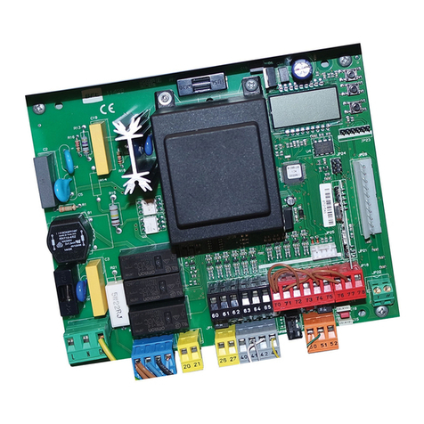
The THALIA control panel comes with standard factory settings. Any change
must be made using the programmer with built-in display or universal handheld
programmer.
The Control unit completely supports the EELINK protocol.
Its main features are:
- Control of 1 or 2 24V BT motors
Note: 2 motors of the same type must be used.
- Electronic torque control with obstacle detection
- Limit switch control inputs based on motor selected
- Separate inputs for safety devices
- Built-in radio receiver rolling code with transmitter cloning.
The board has a terminal strip of the removable kind to make maintenance
or replacement easier. It comes with a series of prewired jumpers to make the
installer’s job on site easier.
Thejumpersconcernterminals:70-71,70-72,70-74.Iftheabove-mentioned
terminals are being used, remove the relevant jumpers.
TESTING
TheTHALIA panelcontrols(checks)thestartrelaysandsafetydevices(photocells)
before performing each opening and closing cycle.
If there is a malfunction, make sure that the connected devices are working
properly and check the wiring.
3) TECHNICAL SPECIFICATIONS
Power supply 220-230V 50/60 Hz*
Low voltage/mains insulation > 2MOhm 500V
Operating temperature range -20 / +55°C
Thermal overload protection Software
Dielectric rigidity mains/LV 3750V~ for 1 minute
Motor output current max. 7.5A+7.5A
Motor relay switching current
10A
Maximum motor power 180W + 180W (24V )
Accessories power supply 24V~ (demand max. 1A)
24V~safe
AUX 0 NO 24V powered contact (max.1A)
AUX 3 NO contact (24V~/max.1A)
Fuses see Fig. C
N° of combinations 4 billion
Max.n° of transmitters that can be memorized
63
(*other voltages to order)
Usable transmitter versions:
All ROLLING CODE transmitters compatible with
4) TUBE ARRANGEMENT Fi g. A
5) TERMINAL BOARD WIRING Fig. C
WARNINGS - When performing wiring and installation, refer to the standards in
force and, whatever the case, apply good practice principles.
Wirescarryingdierentvoltagesmustbekept physicallyseparatefromeachother,
or they must be suitably insulated with at least 1mm of additional insulation.
Wiresmustbe securedwith additionalfasteningneartheterminals,usingdevices
such as cable clamps.
All connecting cables must be kept far enough away from the dissipater.
WARNING! For connection to the mains power supply, use a multicore cable
with a cross-sectional area of at least 3x1.5mm2 of the kind provided for
by the regulations in force. To connect the motors, use a cable with a cross-
sectional area of at least 1.5mm2 of the kind provided for by the regulations
in force. The cable must be type H05RN-F at least.
Terminal Denition Description
Power supply
L LINE Single-phase power supply 220-230V 50/60 Hz*
N NEUTRAL
JP5 TRANSF PRIM Transformer primary winding connection, 220-230V.
JP7
JP21 TRANSF SEC
Board power supply:
24V~ Transformer secondary winding
24V= Buer battery power supply
Motor
10 MOT1 + Connection motor 1. Time lag during closing.
Check connections shown in Fig.E
11 MOT1 -
14 MOT2 + Connection motor 2. Time lag during opening.
Check connections shown in Fig.E
15 MOT2 -
Aux
20 AUX 0 - 24V
POWERED
CONTACT (N.O.)
(MAX. 1A)
AUX 0 congurable output - Default setting FLASHING LIGHT.
2ND RADIO CHANNEL/ SCA GATE OPEN LIGHT/ COURTESY LIGHT command/ ZONE LIGHT command/ STAIR LIGHT/ GATE
OPEN ALARM/ FLASHING LIGHT/ SOLENOID LATCH/ MAGNETIC LOCK/ MAINTENANCE/ FLASHING LIGHT AND MAINTE-
NANCE. Refer to“AUX output conguration”table.
21
26 AUX 3 - FREE
CONTACT
(N.O.)
(Max. 24V 1A)
AUX 3 congurable output - Default setting 2ND RADIO CHANNEL Output.
2ND RADIO CHANNEL/ SCA GATE OPEN LIGHT/ COURTESY LIGHT command/ ZONE LIGHT command/ STAIR LIGHT/ GATE
OPEN ALARM/ FLASHING LIGHT/ SOLENOID LATCH/ MAGNETIC LOCK.
Refer to“AUX output conguration”table.
27
Limit switch for
ELI 250 BT
VIRGO SMART BT A
ELI BT A35 LS
ELI BT A40 LS
5 wires
41 + REF SWE Limit switch common
42 SWC 1 Motor 1 closing limit switch SWC1 (N.C.).
43 SWO 1 Motor 1 opening limit switch SWO1 (N.C.).
44 SWC 2 Motor 2 closing limit switch SWC2 (N.C.).
45 SWO 2 Motor 2 opening limit switch SWO2 (N.C.).
Limit switch for
PHOBOS N BT
IGEA BT
SUB BT
PHOBOS BT A
KUSTOS BT A VIRGO
SMART BT A
3 wires
42 SW 1 Limit switch control motor 1.
For actuators with single-wire limit switch control.
43 SW 2 Limit switch control motor 2.
For actuators with single-wire limit switch control.
Limit switch for
GIUNO ULTRA BT A20
GIUNO ULTRA BT A50
E5 BT A18
E5 BT A12
40 - REF SWE Limit switch common
42 SW 1 Limit switch control motor 1.
43 SW 2 Limit switch control motor 2.
Limit switch for
ELI BT A35 LS
ELI BT A40 LS
40 - REF SWE Encoder power supply, white cable
41 + REF SWE Encoder power supply, brown cable
42 ENC M1 Engine 1 encoder signal, green cable
Close the jumper JP28
43 ENC M2 Engine 2 encoder signal, green cable
Close the jumper JP29
Accessories
power supply
50 24V- Accessories power supply output.
51 24V+
52 24 Vsafe+ Tested safety device power supply output (photocell transmitter and safety edge transmitter).
Output active only during operating cycle.
THALIA - 31
D814123 0AA00_01

INSTALLATION MANUAL
Terminal Denition Description
Commands
60 Common IC 1 and IC 2 inputs common
61 IC 1 Congurable command input 1 (N.O.) - Default START E.
START E / START I / OPEN / CLOSE / PED / TIMER / TIMER PED
Refer to the“Command input conguration” table.
62 IC 2 Congurable command input 2 (N.O.) - Default PED.
START E / START I / OPEN / CLOSE / PED / TIMER / TIMER PED
Refer to the“Command input conguration” table.
Safety devices
70 Common STOP, SAFE 1 and SAFE 2 inputs common
71 STOP The command stops movement. (N.C.)
If not used, leave jumper inserted.
72 SAFE 1
Congurable safety input 1 (N.C.) - Default PHOT.
PHOT / PHOT TEST / PHOT OP / PHOT OP TEST / PHOT CL / PHOT CL TEST / BAR / BAR TEST / BAR 8K2 /
BAR OP / BAR OP
TEST / BAR 8K2 OP/ BAR CL / BAR CL TEST / BAR 8K2 CL
Refer to the“Safety input conguration”table.
73 FAULT 1 Test input for safety devices connected to SAFE 1.
74 SAFE 2
Congurable safety input 2 (N.C.) - Default BAR.
PHOT / PHOT TEST / PHOT OP / PHOT OP TEST / PHOT CL / PHOT CL TEST / BAR / BAR TEST / BAR 8K2 /
BAR OP / BAR OP TEST
/ BAR 8K2 OP/ BAR CL / BAR CL TEST / BAR 8K2 CL
Refer to the“Safety input conguration”table.
75 FAULT 2 Test input for safety devices connected to SAFE 2.
Antenna
Y ANTENNA Antenna input.
Use an antenna tuned to 433MHz. Use RG58 coax cable to connect the Antenna and Receiver. Metal bodies close to the
antenna can interfere with radio reception. If the transmitter’s range is limited, move the antenna to a more suitable
position.
# SHIELD
AUX output conguration
Aux logic= 0 - 2ND RADIO CHANNEL output.
Contact stays closed for 1s when 2nd radio channel is activated.
Aux logic= 1 - SCA GATE OPEN LIGHToutput.
Contact stays closed during opening and with leaf open, intermittent during closing, open with leaf closed.
Aux logic= 2 - COURTESY LIGHT command output.
Contact stays on for 90 seconds after the last operation.
Aux logic= 3 - ZONE LIGHT command output.
Contact stays closed for the full duration of operation.
Aux logic= 4 - STAIR LIGHT output.
Contact stays closed for 1 second at start of operation.
Aux logic= 5 - GATE OPEN ALARM output.
Contact stays closed if the leaf stays open for double the set TCA time.
Aux logic= 6 - FLASHING LIGHT output.
Contact stays closed while leaves are operating.
Aux logic= 7 - SOLENOID LATCH output.
Contact stays closed for 2 seconds each time gate is opened.
Aux logic= 8 - MAGNETIC LOCK output.
Contact stays closed while gate is closed.
Aux logic= 9 - MAINTENANCE output.
Contact stays closed once the value set for the Maintenance parameter is reached, to report that maintenance is required.
Aux logic= 10 - FLASHING LIGHT AND MAINTENANCE output.
Contact stays closed while leaves are operating. If the value set for the Maintenance parameter is reached, once the gate has nished moving and the leaf is closed, the contact closes
for 10 sec. and opens for 5 sec. 4 times to report that maintenance is required.
Command input conguration
IC logic= 0 - Input congured as Start E. Operation according to STEP-BY-STEP MOV. logic. External start for trac light control.
IC logic= 1 - Input congured as Start I. Operation according to STEP-BY-STEP MOV. logic. Internal start for trac light control.
IC logic= 2 - Input congured as Open.
The command causes the leaves to open. If the input stays closed, the leaves stay open until the contact is opened. When the contact is open, the automated device closes following the TCA time,
where activated.
IC logic= 3 - Input congured as Closed.
The command causes the leaves to close.
IC logic= 4 - Input congured as Ped.
The command causes the leaf to open to the pedestrian (partial) opening position. Operation according to STEP-BY-STEP. logic
IC logic= 5 - Input congured as Timer.
Operation same as open except closing is guaranteed even after a mains power outage.
IC logic= 6 - Input congured as Timer Ped.
The command causes the leaf to open to the pedestrian (partial) opening position. If the input stays closed, the leaf stays open until the contact is opened. If the input stays closed and a Start E,
Start I or Open command is activated, a complete opening-closing cycle is performed before returning to the pedestrian opening position. Closing is guaranteed even after a mains power outage.
Safety input conguration
SAFE logic= 0 - Input congured as Phot (photocell) non tested (*). (g.F, ref.1).
Enables connection of devices not equipped with supplementary test contacts. When beam is broken, photocells are active during both opening and closing. When beam is broken
during closing, movement is reversed only once the photocell is cleared. If not used, leave jumper inserted.
SAFE logic= 1 - Input congured as Phot test (tested photocell). (g.F, ref.2).
Switches photocell testing on at start of operation. When beam is broken, photocells are active during both opening and closing. When beam is broken during closing, movement is
reversed only once the photocell is cleared.
SAFE logic= 2 - Input congured as Phot op (photocell active during opening only) non tested (*). (g.F, ref.1).
Enables connection of devices not equipped with supplementary test contacts. In the event beam is broken, photocell operation is disabled during closing. During opening, stops
motion for as long as the photocell beam stays broken. If not used, leave jumper inserted.
SAFE logic= 3 - Input congured as Phot op test (tested photocell active during opening only (g.F, ref.2).
Switches photocell testing on at start of operation. In the event beam is broken, photocell operation is disabled during closing. During opening, stops motion for as long as the photocell beam stays broken.
SAFE logic= 4 - Input congured as Phot cl (photocell active during closing only) non tested (*). (g.F, ref.1).
Enables connection of devices not equipped with supplementary test contacts. In the event beam is broken, photocell operation is disabled during opening. During closing,
movement is reversed immediately. If not used, leave jumper inserted.
SAFE logic= 5 - Input congured as Phot cl test (tested photocell active during closing only (g.F, ref.2).
Switches photocell testing on at start of operation. In the event beam is broken, photocell operation is disabled during opening. During closing, movement is reversed immediately.
SAFE logic= 6 - Input congured as Bar (safety edge) non tested (*). (g.F, ref.3).
Enables connection of devices not equipped with supplementary test contacts. The command reverses movement for 2 sec.. If not used, leave jumper inserted.
SAFE logic= 7 - Input congured as Bar (tested safety edge (g.F, ref.4).
Switches safety edge testing on at start of operation. The command reverses movement for 2 sec.
SAFE logic= 8 - Input congured as Bar 8k2 (g.F, ref.5). Input for resistive edge 8K2.
The command reverses movement for 2 sec.
32 - THALIA
D814123 0AA00_01
ENGLISH
INSTALLATION MANUAL
6) MOTOR WIRING Fig. E
7) SAFETY DEVICES
Note: only use receiving safety devices with free changeover contact.
7.1) TESTED DEVICES Fig. F
7.2 CONNECTION OF 1 PAIR OF NONCHECKED PHOTOCELLS FIG. D1
7.3 CONNECTION OF 1 PAIR OF CHECKED PHOTOCELLS FIG. D2
8 CALLING UP MENUS: FIG. 1
8.1) PARAMETERS MENU PARA PARAMETERS TABLE “A”
8.2) LOGIC MENU LOGICLOGIC TABLE“B”
8.3) RADIO MENU radio RADIO TABLE“C”
- IMPORTANT NOTE: THE FIRST TRANSMITTER MEMORIZED MUST BE
IDENTIFIED BY ATTACHING THE KEY LABEL (MASTER).
In the event of manual programming, the rst transmitter assigns the RECEIVER’S
KEY CODE: this code is required to subsequently clone the radio transmitters.
The Clonix built-in on-board receiver also has a number of important advanced features:
• Cloning of master transmitter (rolling code or xed code).
• Cloning to replace transmitters already entered in receiver.
• Transmitter database management.
• Receiver community management.
To use these advanced features, refer to the universal handheld programmer’s
instructions and to the general receiver programming guide.
8.4 DEFAULT MENU default
Restores the controller’s DEFAULT factory settings. Following this reset, you will
need to run the AUTOSET function again.
8.5 LANGUAGE MENU language
Used to set the programmer’s language on the display.
8.6 AUTOSET MENU AUTOset
•
Launch an autoset operation by going to the relevant menu.
•
As soon as you press the OK button, the“.... .... ....”message is displayed and the control
unitcommandsthedevicetoperformafullcycle(openingfollowedbyclosing),during
which the minimum torque value required to move the leaf is set automatically.
The number of cycles required for the autoset function can range from 1 to 3.
During this stage, it is important to avoid breaking the photocells’beams and not
to use the START and STOP commands or the display.
Once this operation is complete, the control unit will have automatically set the
optimumtorquevalues.Checkthemand,wherenecessary,editthemasdescribed
in the programming section.
WARNING!! Check that the force of impact measured at the points
provided for by standard EN 12445 is lower than the value laid down
by standard EN 12453.
Impact forces can be reduced by using deformable edges.
Warning!!Whiletheautosetfunctionisrunning,theobstacledetection
function is not active. Consequently, the installer must monitor the
automated system’s movements and keep people and property out
of range of the automated system.
8.7)INSTALLATION TEST PROCEDURE
1. Run the AUTOSET cycle (*)
2. Check the impact forces: if they fall within the limits (**) skip to point 10 of the
procedure, otherwise
3. Where necessary, adjust the speed and sensitivity (force) parameters: see
parameters table.
4. Check the impact forces again: if they fall within the limits (**) skip to point 10
of the procedure, otherwise
5. Apply a shock absorber prole
6. Check the impact forces again: if they fall within the limits (**) skip to point 10
of the procedure, otherwise
7. Apply pressure-sensitive or electro-sensitive protective devices (such as a
safety edge) (**)
8. Check the impact forces again: if they fall within the limits (**) skip to point 10
of the procedure, otherwise
9. Allow the drive to move only in“Deadman”mode
10.Makesurealldevicesdesignedtodetectobstacleswithinthesystem’soperating
range are working properly
(*) Before running the autoset function, make sure you have performed all the
assembly and make-safe operations correctly, as set out in the installation
warnings in the drive’s manual.
(**) Based on the risk analysis, you may nd it necessary to apply sensitive
protective devices anyway
8.8) LIMIT STOP ADJUSTMENT MENU (REG. FC)
Used to adjust the limit stops for motors equipped with encoder; moreover,
for motors equipped with independent limit stop wiring harness allows the
correct positioning of the leaf for the subsequent limit stop adjustment. For
motors not specied, the menu is not active and the message”unavailable”is
shown on the display
NOTE: these manoeuvres are performed in person preset mode, at slow speed,
without the intervention of the safety devices.
8.8.1) GIUNO ULTRA BT A20, GIUNO ULTRA BT A50
Using the„+/-”buttons on the display, bring the leaf in the desired position. To
adjust the limit stops, refer to the settings for limit stop adjustment provided in
the GIUNO ULTRA motor manual.
8.8.2) E5 BT A12, E5 BT A18
Using the„+/-”buttons on the display, bring the leaf in the position indicated
by the display (opening or closing). Once the desired position is reached,
conrm the position by pressing the OK button. For E5 motors, the leaf can be
manually positioned close to the limit stops by pushing the gate; then move
the gate using the„+/-”button until it is against the mechanical stopper. To
conrm the position, or use the OK button or the radio control (previously
stored).
9) CLOSING LIMIT SWITCH PRESSURE Fig. G Ref. A-B
OPENING DIRECTION Fig. E
10) CONNECTION WITH EXPANSION BOARDS AND UNIVERSAL HANDHELD
PROGRAMMER VERSION> V1.40 (Fig. H) Refer to specic manual.
11) U-LINK OPTIONAL MODULES
Refer to the U-link instructions for the modules.
The use of some models causes lowered radio capacity. Adjust the system using an
appropriate antenna tuned to 433MHxz.
12) SOLENOID LOCK Fig. I
SOLENOID LOCK
WARNING: In the case of leaves longer than 3m, it is essential to install
a solenoid lock.
Fig. I shows a sample connection of an ECB 24V~ solenoid latch connected to
the THALIA control panel.
In order to control the solenoid lock, the THALIA panel needs a special board
mod. ME BT.
13) RESTORING FACTORY SETTINGS (Fig.J)
WARNING: this operation will restore the control unit’s factory settings and all
transmitters stored in its memory will be deleted.
WARNING! Incorrect settings can result in damage to property and injury to
people and animals.
- Cut o power to the board (Fig.J ref.1)
- Open the Stop input and press the - and OK keys together (Fig.J ref.2)
- Switch on the board’s power (Fig.J ref.3)
-The display will read RST; conrm within 3 sec. by pressing the OK key (Fig.J ref.4)
- Wait for the procedure to nish (Fig.J ref.5)
- Procedure nished (Fig.J ref.6)
WARNING! Incorrect settings can result in damage to property and injury to people
and animals.
WARNING: Check that the force of impact measured at the points
provided for by standard EN 12445 is lower than the value laid down
by standard EN 12453.
Impact forces can be reduced by using deformable edges.
For best results, it is advisable to run the autoset function with the motors idle (i.e.
not overheated by a considerable number of consecutive operations).
Safety input conguration
SAFE logic=9 Input congured as Bar op, safety edge with active inversion only while opening, if activated while closing, the automation stops (STOP) (Fig. F, ref. 3).
Allows connecting devices not tted with supplementary test contact. The operation while opening causes the movement to be reversed for 2 seconds, the operation while closing causes the
automation to stop. If not used, leave jumper inserted.
SAFE logic=10 Input congured as Bar op test, safety edge checked with active inversion only while opening, if activated while closing, the automation stops (STOP) (Fig. F, ref. 4).
Activates testing safety edges when starting operation. The operation while opening causes the movement to be reversed for 2 seconds, the operation while closing causes the automation to stop.
SAFE logic=11 Input congured as Bar 8k2 op, 8k2 safety edge with active inversion only while opening, if activated while closing, the automation stops (STOP) (Fig. F, ref. 5).
The operation while opening causes the movement to be reversed for 2 seconds, the operation while closing causes the automation to stop.
SAFE logic=12 Input congured as Bar cl, safety edge with active inversion only while closing, if activated while opening, the automation stops (STOP) (Fig. F, ref. 3).
Allows connecting devices not tted with supplementary test contact. The operation while closing causes the movement to be reversed for 2 seconds, the operation while opening
causes the automation to stop. If not used, leave jumper inserted.
SAFE logic=13 Input congured as Bar cl test, safety edge checked with active inversion only while closing, if activated while opening, the automation stops (STOP) (Fig. F, ref. 4).
Activatestestingsafetyedgeswhenstartingoperation.Theoperationwhileclosingcausesthemovementtobereversedfor2seconds,theoperationwhileopeningcausestheautomationtostop.
SAFE logic=14 Input congured as Bar 8k2 cl, safety edge with active inversion only while closing, if activated while opening, the automation stops (STOP) (Fig. F, ref. 5).
The operation while closing causes the movement to be reversed for 2 seconds, the operation while opening causes the automation to stop.
(*) If“D”type devices are installed (as dened by EN12453), connect in unveried mode, foresee mandatory maintenance at least every six months.
THALIA - 33
D814123 0AA00_01

INSTALLATION MANUAL
TABLE“A” PARAMETERS MENU - PARA
Parameter min. max. Default
Personal
Denition Description
OPEN DELAY
TI E 0 10 3 Motor 2 opening delay
time [s] Motor 2 opening delay time with respect to motor 1.
CLS DELAY
TI E 0 25 6 Motor 1 closing delay
time [s]
Motor 1 closing delay time with respect to motor 2.
NOTE: if the time is set to maximum, before starting, engine 1 waits for the complete
shut down of engine 2.
TCA 0 120 10 Automatic closing time [s] Waiting time before automatic closing.
TRF.LGHT.
CLR.T 1 180 40
Time-to-clear trac light
zone [s]
Time-to-clear for the zone run through by trac controlled by the trac light.
OP.DIST.
SLOUD 0 50 10 Slow-down distance during
opening [%]
Slow-down distance for motor(s) during opening, given as a percentage of total travel.
WARNING: Once the parameter has been edited, a complete uninterrupted opening-
closing cycle is required.
WARNING: when the display reads“SET”, obstacle detection is not active.
ATTENTION: with actuators with integrated locks, the permanently active slowdown
to a value higher than 5 is mandatory.
WARNING: in GIUNO, the slow-down distance is set with the sliding sensors
ATTENTION: for the ELI BT A35 engine type, the slowing cannot be excluded; values
below 10% will be considered to be 10%.
CL.DIST.
SLOUD 0 50 10 Slow-down distance during
closing [%]
Slow-down distance for motor(s) during closing, given as a percentage of total travel.
WARNING: Once the parameter has been edited, a complete uninterrupted opening-
closing cycle is required.
WARNING: when the display reads“SET”, obstacle detection is not active.
ATTENTION: with actuators with integrated locks, the permanently active slowdown
to a value higher than 5 is mandatory.
WARNING: in GIUNO, the slow-down distance is set with the sliding sensors
ATTENTION: for the ELI BT A35 engine type, the slowing cannot be excluded; values
below 10% will be considered to be 10%.
DIST.DECEL 0 50 15 Deceleration distance [%]
Deceleration distance (switch from running speed to slow-down speed) for motor(s) both
duringopeningandduringclosing,givenasapercentageoftotaltravel.WARNING:Oncethe
parameterhasbeenedited,acompleteuninterruptedopening-closingcycleisrequired.
WARNING: when the display reads“SET”, obstacle detection is not active.
PARTIAL
OPENING 10 99 99 Partial opening M1 [%]
Partial opening distance as a percentage of total opening following activation of PED
pedestrian command.
OP.FORCE 1 99 50 Leaf force during
opening [%]
Force exerted by leaf/leaves during opening. This is the percentage of force delivered,
beyond the force stored during the autoset cycle (and subsequently updated), before an
obstacle alarm is generated.
The parameter is set automatically by the autoset function.
WARNING: It aects impact force directly: make sure that current safety
requirements are met with the set value (*). Install anti-crush safety devices
where necessary (**).
CLS.FORCE 1 99 50 Leaf force during
closing [%]
Force exerted by leaf/leaves during closing. This is the percentage of force delivered,
beyond the force stored during the autoset cycle (and subsequently updated), before an
obstacle alarm is generated.
The parameter is set automatically by the autoset function.
WARNING: It aects impact force directly: make sure that current safety
requirements are met with the set value (*). Install anti-crush safety devices
where necessary (**).
OP SPEED 15 99 99 Opening speed [%}
Percentage of maximum speed that can be reached by motor(s) during opening.
WARNING: Once the parameter has been edited, a complete uninterrupted
opening-closingcycleisrequired.WARNING:whenthedisplayreads"SET",obstacle
detection is not active.
CL SPEED 15 99 99 Closing speed [%] Percentageofmaximumspeedthatcanbereachedbymotor(s)during closing.WARNING:
Oncetheparameterhasbeenedited,acompleteuninterruptedopening-closingcycle
isrequired. WARNING:whenthedisplayreads"SET",obstacledetectionisnotactive.
SLOW SPEED 15 99 25 Slow-down speed [%]
Opening and closing speed of motor(s) during slow-down stage, given as a percentage of
maximum running speed. WARNING: Once the parameter has been edited, a complete
uninterrupted opening-closing cycle is required. WARNING: When the display reads
“”SET””, obstacle detection is not active.
ATTENTION: for the ELI BT A35 engine type, the slowing cannot be excluded; values
below 50% will be considered to be 50%.
ainte-
nance 0 250 0
Programming number of
operations for maintenance
threshold
[in hundreds]
Allows you to set a number of operations after which the need for maintenance will
be reported on the AUX output congured as Maintenance or Flashing Light and
Maintenance .
(*) In the European Union, apply standard EN 12453 for force limitations, and standard EN 12445 for measuring method.
(**) Impact forces can be reduced by using deformable edges.
34 - THALIA
D814123 0AA00_01
ENGLISH
INSTALLATION MANUAL
TABLE“B” LOGIC MENU - logic
Logic Denition
Default
Cross out
setting
used Optional extras
OTOR TYPE
Motor type
(Set the type of motor
connected to the
board).
0
0 Motors not active
1 ELI 250 BT
2 PHOBOS N BT
3 IGEA BT
4 NOT MANAGED
5 NOT MANAGED
6 SUB BT
7 KUSTOS BT A - PHOBOS BT A
8 GIUNO ULTRA BT A 20 - GIUNO ULTRA BT A50
9 VIRGO SMART BT A - 5 wires
10 VIRGO SMART BT A - 3 wires
11 E5 BT A18
12 E5 BT A12
13 ELI BT A40 LS
14 ELI BT A35 LS
15 ELI BT A35
16 ELI BT A40
TCA Automatic Closing
Time 00 Logic not enabled
1 Switches automatic closing on
FAST CLS. Fast closing 00 Logic not enabled
1 Closes 3 seconds after the photocells are cleared before waiting for the set TCA to elapse.
STEP-BY-STEP
OVE NT
Step-by-step
movement 0
0 Inputs congured as Start E, Start I, Ped operate with 4-step logic.
1Inputs congured as Start E, Start I, Ped operate with 3-step logic. Pulse during closing reverses movement.
2 Inputs congured as Start E, Start I, Ped operate with 2-step logic. Movement reverses with each pulse.
PRE-ALAR Pre-alarm 00 The ashing light comes on at the same time as the motor(s) start.
1 The ashing light comes on approx. 3 seconds before the motor(s) start.
HOLD-TO-RUN Deadman 0
0 Pulse operation.
1
Deadman mode.
Input 61 is congured as OPEN UP.
Input 62 is congured as CLOSE UP.
Operation continues as long as the OPEN UP or CLOSE UP keys are held down.
WARNING: safety devices are not enabled.
2
Emergency Deadman mode. Usually pulse operation.
If the board fails the safety device tests (photocell or safety edge, Er0x) 3 times in a row, the device is
switched to Deadman mode, which will stay active until the OPEN UP or CLOSE UP keys are released.
Input 61 is congured as OPEN UP.
Input 62 is congured as CLOSE UP.
WARNING: with the device set to Emergency Deadman mode, safety devices are not enabled.
IBL OPEN Block pulses during
opening 00 Pulse from inputs congured as Start E, Start I, Ped has eect during opening.
1 Pulse from inputs congured as Start E, Start I, Ped has no eect during opening.
iBL TCA Block pulses during
TCA 00 Pulse from inputs congured as Start E, Start I, Ped has eect during TCA pause.
1 Pulse from inputs congured as Start E, Start I, Ped has no eect during TCA pause.
IBL CLOSE Block pulses during
closing 00 Pulse from inputs congured as Start E, Start I, Ped has eect during closing.
1 Pulse from inputs congured as Start E, Start I, Ped has no eect during closing.
RA BLOW C.OP Hammer during
opening 0
0 Logic not enabled
1Before opening completely, the gate pushes for approx. 2 seconds as it closes. This allows the solenoid
lock to be released more easily.
IMPORTANT - Do not use this function if suitable mechanical stops are not in place.
RA BLOW C.CL Hammer during
closing 0
0 Logic not enabled
1Before closing completely, the gate pushes for approx. 2 seconds as it opens. This allows the solenoid lock
to be released more easily.
IMPORTANT - Do not use this function if suitable mechanical stops are not in place.
BLOC PERSIST Stop maintenance 0
0 Logic not enabled
1
If motors stay idle in fully open or fully closed position for more than one hour, they are switched on in
the direction of the stop for approx. 3 seconds. This operation is performed every hour.
NB: In hydraulic motors, this function serves to compensate a possible reduction in the volume of oil due
to a drop in temperature during extended pauses, such as during the night, or due to internal leakage.
IMPORTANT - Do not use this function if suitable mechanical stops are not in place.
PRESS SWC Closing limit switch
pressure 0
0Movement is stopped only when the closing limit switch trips: in this case, the tripping of the closing
limit switch must be adjusted accurately (Fig.G Ref.B).
1
Use when there is a mechanical stop in closed position.
This function allows leaves to press against the mechanical stop without the Amperostop sensor inter-
preting this as an obstacle.
Thus the rod continues its stroke for a few seconds after meeting the closing limit switch or as far as the
mechanical stop. In this way, the leaves come to rest perfectly against the stop by allowing the closing
limit switches to trip slightly earlier (Fig.G Ref.A).
ICE Ice feature 0
0 The Amperostop safety trip threshold stays at the same set value.
1
The controller automatically adjusts the obstacle alarm trip threshold at each start up.
Check that the force of impact measured at the points provided for by standard EN 12445 is lower than
the value laid down by standard EN 12453. If in doubt, use auxiliary safety devices.
This feature is useful when dealing with installations running at low temperatures.
WARNING: once this feature has been activated, you will need to perform an autoset opening and closing
cycle.
1 OT.ON 1 motor active 00 Both motors active (2 leaves).
1 Only motor 1 active (1 leaf).
THALIA - 35
D814123 0AA00_01
Other manuals for THALIA
3
Table of contents
Other BFT Control Panel manuals

BFT
BFT Rigel 6 QRG User manual

BFT
BFT SHYRA AC SL User manual

BFT
BFT ALENA SW2 CPEM User manual

BFT
BFT ALTAIR-P User manual

BFT
BFT LEO B CBB 3 400 W01 User manual

BFT
BFT ZARA BT A80 User manual

BFT
BFT ZARA BTL2 User manual

BFT
BFT LEO B CBB 3 400 W01 User manual

BFT
BFT VISTA SEL User manual

BFT
BFT PERSEO CBD 230.P SD User manual
Popular Control Panel manuals by other brands

Matrix Switch Corporation
Matrix Switch Corporation MSC-CP16X1E product manual

urmet domus
urmet domus 1067 Series user manual

ABB
ABB ACS850 series Quick start up guide

System Sensor
System Sensor PDRP-2001 instruction manual

Johnson Controls
Johnson Controls T20 instruction sheet

Assa Abloy
Assa Abloy effeff 925 installation manual