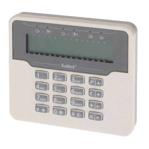
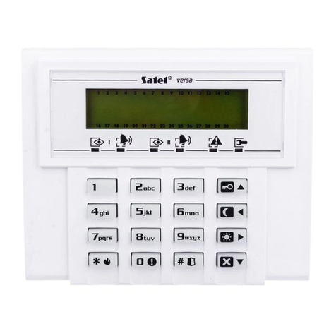
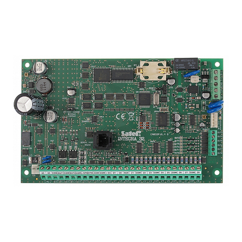
Satel Versa Owner's manual

PROGRAMMING
SATEL sp. z o.o.
ul. Budowlanych 66
80-298 Gdańsk
POLAND
tel. +48 58 320 94 00
www.satel.eu
versa_p_en 11/17
Alarm Control Panel
Firmware Version 1.09

Before you start programming, please read carefully this manual in order to avoid mistakes
that can lead to malfunction or even damage to the equipment.
SATEL's goal is to continually upgrade the quality of its products, which may result in some
changes of their technical specifications and firmware. The current information on
the introduced modifications is available on our website.
Please visit us:
http://www.satel.eu
The declaration of conformity may be consulted at www.satel.eu/ce
Service code: 12345
The following symbols may be used in this manual:
- note,
- caution.

Changes made to the firmware versions 1.08 and 1.09
Global parameters New option: BACKLIGHT OFF ON AC LOSS.
Partitions New option: ENTRY DELAY IN NIGHT ARM.
Ethernet module Changed names of options:
SATEL SERVER (LAN) has been replaced with LAN,
GET DATE AND TIME FROM A TIME SERVER (LAN) has been replaced
with LAN.
New options:
DO NOT REPORT SATEL SERVER CONNECTION TROUBLE,
ALARM 3INCORRECT CODES (MOBILE APPLICATION).
ABAX wireless
system If the ACU-120 / ACU-270 controller with firmware version 5.03 is
connected to the control panel:
you can select whether the AMD-101 detector is to occupy one or
two positions on the list of wireless devices,
the users can replace batteries in the wireless keypad after starting
the REPLACE BAT. function.
APT-100 keyfob LEDs can indicate that partitions are disarmed.
E-mail messaging Changed name of option: E-MAIL MESSAGING (LAN) has been replaced
with LAN.
Entering code After an incorrect code has been entered, the “Wrong code” message
will be displayed on the LCD keypad. The same message will also be
displayed after entering a correct code, when the keypad is blocked.
User functions A new function in the 0.SERVICE submenu: 9.REPLACE BAT.

2 VERSA SATEL
CONTENTS
1. Introduction.....................................................................................................................5
2. Configuring the control panel with keypad ..................................................................5
2.1 Starting the service mode ...................................................................................................... 5
2.2 Starting the service mode “from pins” .................................................................................... 5
2.3 Navigating through the menu and running functions ............................................................. 6
2.3.1 Using the arrow keys ....................................................................................................................... 6
2.3.2 Using the digit shortcuts .................................................................................................................. 6
2.4 “Step by step” programming method ..................................................................................... 6
2.5 Entering data.......................................................................................................................... 7
2.5.1 LCD keypad ..................................................................................................................................... 7
2.5.2 LED keypad ..................................................................................................................................... 9
2.6 Service mode menu ............................................................................................................. 11
2.7 Hiding the service mode ...................................................................................................... 16
2.8 Exiting the service mode...................................................................................................... 16
3. Configuring the control panel with DLOADX program..............................................17
3.1 Main menu of the DLOADX program ................................................................................... 17
3.1.1 Buttons........................................................................................................................................... 17
3.1.2 Changing the DLOADX program access code.............................................................................. 19
3.2 Parameters related to communication between the control panel and DLOADX program.. 20
3.2.1 Communication identifiers ............................................................................................................. 20
3.2.2 Modem communication parameters .............................................................................................. 20
3.2.3 Ethernet communication parameters............................................................................................. 22
3.3 Local programming .............................................................................................................. 22
3.3.1 Starting local programming............................................................................................................ 22
3.3.2 Finishing local programming.......................................................................................................... 23
3.4 Remote programming .......................................................................................................... 23
3.4.1 Programming via modem............................................................................................................... 23
3.4.2 Programming over Ethernet .......................................................................................................... 25
4. Global parameters ........................................................................................................26
4.1 Programming the global parameters.................................................................................... 26
4.2 Global options...................................................................................................................... 27
4.3 Global times......................................................................................................................... 29
4.4 Arming.................................................................................................................................. 30
4.5 Other global parameters ...................................................................................................... 31
5. Partitions.......................................................................................................................31
5.1 Configuring the partitions..................................................................................................... 31
5.2 Partition parameters............................................................................................................. 31
6. Zones.............................................................................................................................33
6.1 Programming the EOL resistor values ................................................................................. 33
6.2 Configuring the zone parameters and options..................................................................... 34
6.3 Zone parameters.................................................................................................................. 35
6.4 Zone types ........................................................................................................................... 37
6.5 Zone options ........................................................................................................................ 38
6.6 Hardware ............................................................................................................................. 40
7. Outputs..........................................................................................................................41
7.1 Configuring the outputs........................................................................................................ 41
7.2 Output functions................................................................................................................... 41
7.3 Output parameters ...............................................................................................................42
7.4 Output options...................................................................................................................... 44
7.5 Quick control of outputs ....................................................................................................... 46

SATEL VERSA 3
8. Devices..........................................................................................................................47
8.1 Configuring the devices........................................................................................................47
8.2 Keypad ................................................................................................................................. 47
8.2.1 Parameters and options .................................................................................................................47
8.2.2 Volume............................................................................................................................................49
8.2.3 Proximity cards ...............................................................................................................................50
8.3 Ethernet module................................................................................................................... 51
8.3.1 LAN.................................................................................................................................................53
8.4 ABAX wireless system controller.......................................................................................... 53
8.4.1 Parameters and options of the controller .......................................................................................53
8.4.2 Parameters and options of ABAX system wireless devices...........................................................55
8.4.3 Configuring the ABAX wireless devices .........................................................................................57
8.4.4 Specific character of the operation of wireless devices .................................................................61
8.5 433 MHz wireless system controller.....................................................................................64
8.5.1 Presence control of 433 MHz wireless detectors ...........................................................................64
8.5.2 Configuring the 433 MHz wireless detectors..................................................................................64
8.5.3 433 MHz wireless detectors and zone programming .....................................................................65
8.6 Proximity card arm/disarm device ........................................................................................66
9. Timers............................................................................................................................67
9.1 Programming the timers....................................................................................................... 67
9.2 Timer parameters................................................................................................................. 68
10. Reporting.......................................................................................................................68
10.1 Configuring the reporting......................................................................................................68
10.2 Reporting parameters and options....................................................................................... 68
10.2.1 Options ...........................................................................................................................................68
10.2.2 Station 1 / Station 2 ........................................................................................................................69
10.2.3 Test transmissions..........................................................................................................................71
10.3 SIA-IP................................................................................................................................... 71
10.3.1 Monitoring station 1 / Monitoring station 2......................................................................................71
10.4 Event codes.......................................................................................................................... 72
10.5 Starting the reporting............................................................................................................ 72
10.5.1 Reporting via telephone line ...........................................................................................................73
10.5.2 Reporting via Ethernet network ......................................................................................................73
11. Messaging.....................................................................................................................73
11.1 Telephone messaging .......................................................................................................... 74
11.1.1 Configuring the telephone messaging............................................................................................74
11.1.2 Parameters and options of the telephone messaging....................................................................74
11.1.3 Event assignment ...........................................................................................................................75
11.1.4 SMS/Pager messages....................................................................................................................75
11.1.5 Starting the telephone messaging..................................................................................................75
11.2 E-mail messaging................................................................................................................. 76
11.2.1 Configuring the e-mail messaging..................................................................................................76
11.2.2 Parameters and options of the e-mail messaging..........................................................................76
11.2.3 Starting the e-mail messaging........................................................................................................77
12. User schedules.............................................................................................................78
12.1 Configuring the user schedules............................................................................................78
12.2 Parameters of the user schedule ......................................................................................... 78
12.3 Functions assigned to keyfob buttons.................................................................................. 80
12.4 Confirmation on LEDs in the APT-100 keyfob...................................................................... 82
13. Compliance with EN 50131 standard requirements for Grade 2..................................82
14. Control panel firmware update....................................................................................83
14.1 Standard update procedure.................................................................................................. 83
14.2 Emergency update procedure .............................................................................................. 83
SATEL VERSA 5
1. Introduction
The VERSA alarm system can be configured by using:
keypad,
computer with DLOADX program installed (locally or remotely).
Local programming (using the keypad or DLOADX program) is possible, if one the following
conditions is met:
PERMANENT ACCESS option is enabled (SERV. ACCESS user function ([code]
0. SERVICE 5. SERV. ACCESS) – see: USER MANUAL) – the option is enabled by default,
access to the control panel has been granted temporarily to the service personnel (ACCESS
TIME user function ([code] 0. SERVICE 6. ACCESS TIME) – see: USER MANUAL).
As required by the standards, the service access after completion of the installation
has to be limited by the administrators.
2. Configuring the control panel with keypad
The control panel can be programmed using the functions available in the service mode. In
case of the LED keypad, programming is subject to some limitations (e.g. entering names is
impossible). Programming the control panel by use of LED keypad is not recommended
by SATEL.
The service mode is indicated on the keypads by means of the LED. The LED is lit on
the keypad in which the service function menu is available, while it is blinking on all the other
keypads. The service mode may also be signaled acoustically, after the corresponding option
is enabled. Additional information is provided by the LED, which is:
– blinking during navigation throughout the menu and submenus,
– lit when any service function is running.
When in the service mode, the alarm system signals no alarms.
2.1 Starting the service mode
1. Enter the service code (by default: 12345) and press the key.
2. Press in turn . The service mode will be started.
2.2 Starting the service mode “from pins”
When entering the service mode in the normal way is not possible (the control panel does not
support keypads, does not accept the service code, etc.), you can use the emergency
procedure, so-called, starting “from pins”.
1. Power off the control panel (disconnect AC mains first, and the battery next).
2. Place a jumper across the RESET pins.
3. Power up the control panel (first connect the battery and then the AC power).
4. Wait a few seconds and remove the jumper from the RESET pins. The control panel will
enter the service mode. The service mode menu will be available on the keypad with the
lowest address (in the case of the wireless keypad, the menu will be displayed after
pressing any key).

6 VERSA SATEL
If the SERVICE MODE FROM RESET PINS option is disabled in the control panel then,
depending on the type of keypad in which the lowest address is set:
LCD: the , and LEDs of the second partition will be lit, and the message
“Restore factory settings ? 1=Yes” will come up on the display,
LED: the and LEDs of the second partition will be lit and the LED will be
blinking rapidly.
Pressing the key will restore the factory default settings of the control panel,
thus making it possible to enter the service mode.
2.3 Navigating through the menu and running functions
2.3.1 Using the arrow keys
This method is only available in the LCD keypad.
1. Using the and keys, find the required submenu (the submenu indicating
cursor: ).
2. Press the or key to enter the submenu (use the key to return to the
previous menu/submenu, and the key to return to the main menu).
3. Repeat the steps 1 and 2 until the required function is found (the function indicating
cursor: ). Press or to start the function.
2.3.2 Using the digit shortcuts
Submenus and functions are numbered. In order to enter a submenu, just press the key with
number corresponding to the submenu number. In order to start a function, press the key
with number corresponding to the function number, and then . You can quickly start the
selected function by entering at once a sequence of some digits (corresponding to the
consecutive submenu numbers and the function number) and pressing .
For example, to start the expander identification function, press in turn the
keys, where:
- entering the 2. HARDWARE submenu,
- entering the 1. KPDS.&EXPS. submenu,
- running the 1. IDENTIFICAT. function.
In the LCD keypad, use the key to return from a submenu to the main menu or from a
function to a submenu, and use the key to return from a submenu to the previous
menu/submenu.
In the LED keypad, use the key to return to the main menu.
Remember that the sequence of digits which starts a function e.g. from the main menu
level will not start the same function from the submenu level.
2.4 “Step by step” programming method
In case of some functions (e.g. configuring the zones, outputs, expanders, etc.), the
programming is effected by using the “step by step” method. After calling the function and
selecting the item to be configured from the list, the first parameter available for programming
will be displayed. After pressing , you will go on to programming another parameter (if
you have entered some changes, they will be saved). Having programmed all parameters,
you will return to the submenu (LCD keypad) / main menu (LED keypad). The and

SATEL VERSA 7
LEDs of the first and second partition show the number of programming step (see: page 10
table 4). Some programming steps may be sometimes not available.
2.5 Entering data
The changes entered will be saved after pressing the key. Use the key to quit
the function without saving changes.
2.5.1 LCD keypad
The data being entered are presented on the display. The method of programming depends
on the type of data to be entered by service function.
Selection from the single-choice list
In the upper line of the display, the function name is presented, and in the lower one – the
currently selected item. You can scroll through the list using the and keys. The
and keys are not used.
Selection from the multiple-choice list
In the upper line of the display, the function name is presented, and in the lower one – one of
the items to choose from. You can scroll through the list using the and keys. The
following symbol is situated in the upper right corner of the display:
– displayed item is selected / option is enabled,
– displayed item is not selected / option is disabled.
Press any numerical key to change the currently shown symbol for another one.
If you want to see the status of all items (these can be e.g. zones, outputs, options, etc.),
press or . The numbers around the display allow the items to be identified. Use
the and keys to move the cursor. After hovering the cursor over the selected
item, you can change its status by pressing any numeric key. If you want to restore the
previous way of presentation of the list, press or .
Entering decimal values
To enter digits, use the numeric keys. The key moves the cursor to the right, and the
or key – to the left.
Entering hexadecimal values
To enter digits, use the numeric keys, and to enter characters from A to F, use the and
keys (keep pressing the key until the required character appears). The key
moves the cursor to the right, and the or key – to the left.
Programming telephone numbers
To enter digits, use the numeric keys, and to enter other characters, use the , ,
and keys (keep pressing the key until the required character appears – see:
table 1). You can enter up to 16 characters. Some of the characters occupy two positions (a,
b, c, d, # and ). If they are used, you can enter less characters than 16.
Shown on the right side in the upper line of the display is information about the letter case:
[ABC] or [abc] (it will be displayed after pressing any key and will be visible for a few seconds
after the last keystroke). Use the and keys to move the cursor. The key
deletes the character on the left side of the cursor.

8 VERSA SATEL
Characters available after next keystroke
key mode [ABC] key mode [abc]
1 # 1 #
2 B C 2 a b c
3 D E F 3 d
4 4
5 5
6 6
7 7
8 8
9 9
0 0
Table 1. Characters available in the keypad when entering telephone numbers (to change the
letter case, press ).
Special character Function description
B switch-over to pulse dialing
C switch-over to tone dialing (DTMF)
D waiting for additional signal
E 3 second pause
F 10 second pause
signal in DTMF mode
# signal # in DTMF mode
a
b other signals generated in DTMF mode
c
d
Table 2. Special character functions.
Entering names
The characters that can be entered by using the keys are presented in Table 3. Keep
pressing the key until the required character appears. Long press the key to display the digit
assigned to it.
Shown on the right side in the upper line of the display is information about the letter case:
[ABC] or [abc] (it will be displayed after pressing any key and will be visible for a few seconds
after the last keystroke).
The key moves the cursor to the right, and the key – to the left. The key
deletes the character on the left side of the cursor.

SATEL VERSA 9
Key Characters available after next keystroke
! ? ' ` " { } $ % & @ \ ^ | # 1
abc2
def3
ghi4
jkl5
mno6
pqrs7
t u v 8
wxyz9
/ = _ < > ( ) [ ] 0. , : ; + -
Table 3. Characters available when entering names. The upper case letters are available
under the same keys (to change the letter case, press ).
2.5.2 LED keypad
The data being entered are presented by means of LEDs. The method of programming
depends on the type of data to be entered by service function.
Selection from the single-choice list
The lit LEDs show the available items on the list. Blinking LED indicates the current position
of the cursor and, consequently, the item which is currently selected. Use the and
keys to move the cursor. The and keys are not used.
Selection from the multiple-choice list
The status of all items available within the function (including e.g. zones, outputs, options,
etc.) is illustrated by LEDs designated by numbers. The steady-on LEDs indicate the selected
items. The blinking LED indicates that that the cursor is there. Use the and keys
to move the cursor. Press any numeric key to change the LED status (to turn it ON or OFF).
The and keys are not used.
Entering decimal values
To enter digits, use the numeric keys. Up to 6 digits can be presented on the LEDs. Each
digit is presented on four LEDs – see Table 4. LEDs 1-4 present the first digit, LEDs 5-8 – the
second, LEDs 9-12 – the third, LEDs 16-19 – the fourth, LEDs 20-23 – the fifth, and LEDs
24-27 – the sixth digit. The arrow keys are not used. The value entered can only be corrected
after restarting the function.
Entering hexadecimal values
To enter digits, use the numeric keys, and to enter characters from A to F, use the and
keys (keep pressing the key until the required character appears). Up to 6 characters
can be presented on the LEDs. Each character is presented on four LEDs – see Table 4.
LEDs 1-4 present the first character, LEDs 5-8 – the second, LEDs 9-12 – the third, LEDs
16-19 – the fourth, LEDs 20-23 – the fifth, and LEDs 24-27 – the sixth character. The arrow
keys are not used. The value entered can only be corrected after restarting the function.

10 VERSA SATEL
LED status Digits and characters
0
– LED OFF
1
– LED ON
2
3
4
5
6
7
8
9
A
B
C
D
E
F
Table 4. The binary mode of presenting digits and characters.
Fig. 1. Examples of presenting decimal values by means of LEDs in the LED keypad. Value
30 (030) is programmed in Example A, and value 160 in Example B.

SATEL VERSA 11
Fig. 2. Examples of presenting hexadecimal values by means of LEDs in the LED keypad.
Two-character value D5 is programmed in Example A, and four-character value E92B in
Example B.
Programming telephone numbers
The telephone numbers are entered in much the same way as in the LCD keypad, however
the LEDs can only present the first 6 characters (only digits and characters B, C, D, E and F
– see: Table 4). The arrow keys are not used. The value entered can only be corrected after
restarting the function.
2.6 Service mode menu
Shown in square brackets are sequences which enable calling up a particular submenu or
starting a particular function from the main menu level.
0. SrvMod config
[00#] 0. Serv.Mode end
[01#] 1. VERSA id.
[02#] 2. DLOADX id.
[04#] 4. DLOADX tel.
[06#] 6. SrvMod opt.
[07#] 7. Restore all
[08#] 8. Default usr.
A. Hide SM now
1. Partitions
[11#] 1. Part. 1 zones
[12#] 2. Part. 2 zones

12 VERSA SATEL
[13] 3. Part. 1 times
[131#] 1. Exit delay
[132#] 2. Entry delay
[133#] 3. Warning
[134#] 4. Verification
[135#] 5. Autoarm delay
[136#] 6. A-arm defer
[14] 4. Part. 2 times
[141#] 1. Exit delay
[142#] 2. Entry delay
[143#] 3. Warning
[144#] 4. Verification
[145#] 5. Autoarm delay
[146#] 6. A-arm defer
[15#] 5. Part. 1 name
[16#] 6. Part. 2 name
[17#] 7. Part. options
2. Hardware
[21] 1. Kpds. & exps.
[211#] 1. Identificat.
[212#] 2. Settings
[select device]
[213#] 3. Wireless dev.
[213#1#] 1. New device.
[213#2#] 2. Config. device
[213#3#] 3. Remove device
[213#4#] 4. Wirelss.zones
[213#5#] 5. Synchronize
[213#6#] 6. Test mode on
[213#7#] 7. Test mode off
[213#8#] 8. Connect msg.
[214#] 4. Options
[217#] 7. Rem.ABAX dev.
[218#] 8. Rem.ABAX kfbs
[219#] 9. Rem.RX k-fobs
[210#] 0. Keypads addr.
[22#] 2. Zones
[select zone]
[23#] 3. Outputs
[select output]
[24] 4. Quick control
[241#] 1. Control 1#/1*
[242#] 2. Control 2#/2*
[243#] 3. Control 3#/3*

SATEL VERSA 13
[244#] 4. Control 4#/4*
[245#] 5. Control 5#/5*
[246#] 6. Control 6#/6*
[247#] 7. Control 7#/7*
[248#] 8. Control 8#/8*
[249#] 9. Control 9#/9*
[240#] 0. Control 0#/0*
[25#] 5. EOL 1 resist.
[26#] 6. EOL 2 resist.
[27#] 7. VERSA zones
3. Global param.
[31#] 1. Options
[32#] 2. Kpds al. time
[33#] 3. Hide arm st.
[34#] 4. AC trbl. delay
[35#] 5. Tel. trbl. del.
[36#] 6. RTC adjustm.
[37#] 7. Daylight sav.
[38#] 8. Summer time
[39#] 9. Winter time
[30#] 0. Min.code len.
4. Timers
[41#] 1. Timer 1 name
[42#] 2. Timer 2 name
[43#] 3. Timer 3 name
[44#] 4. Timer 4 name
5. Monitoring
[50#] 0. Stations
[51] 1. Station 1
[511#] 1. Tel. number
[512#] 2. Tel. format
[513#] 3. Options
[514#] 4. Attempts no.
[515#] 5. Suspens. time
[516] 6. Identifiers
[5161#] 1. Id. 1
[5162#] 2. Id. 2
[5163#] 3. Id. 3
[5160#] 0. System Id.
[517#] 7. T-M/SIA pref.
[518#] 8. StationTCP/IP
[519#] 9. SIA-IP acct
[52] 2. Station 2
[521#] 1. Tel. number

14 VERSA SATEL
[522#] 2. Tel. format
[523#] 3. Options
[524#] 4. Attempts no.
[525#] 5. Suspens. time
[526] 6. Identifiers
[5261#] 1. Id. 1
[5262#] 2. Id. 2
[5263#] 3. Id. 3
[5260#] 0. System Id.
[527#] 7. T-M/SIA pref.
[528#] 8. StationTCP/IP
[529#] 9. SIA-IP acct
[53#] 3. SIA options
[54] 4. Event codes
[541] 1. Partition 1
[5411#] 1. Arm by user
[5412#] 2. Arm other
[5413#] 3. Quick arm
[5414#] 4. Disarm by usr
[5415#] 5. Disarm other
[5416#] 6. Rest. by user
[5417#] 7. Restore other
[5418#] 8. Duress
[5419#] 9. Arming failed
[542] 2. Partition 2
[5421#] 1. Arm by user
[5422#] 2. Arm other
[5423#] 3. Quick arm
[5424#] 4. Disarm by usr
[5425#] 5. Disarm other
[5426#] 6. Rest. by user
[5427#] 7. Restore other
[5428#] 8. Duress
[5429#] 9. Arming failed
[543] 3. Zones
[5431#] 1. Alarm
[5432#] 2. Alarm restore
[5433#] 3. Tamper
[5434#] 4. Tmp restore
[5435#] 5. Trouble
[5436#] 6. Trouble rest.
[5437#] 7. Bypass
[5438#] 8. Unbypass
[544] 4. Wirelss.zones

SATEL VERSA 15
[5441#] 1. Commun. loss
[5442#] 2. Commun. rst.
[5443#] 3. Battery low
[5444#] 4. Battery rst.
[545] 5. Exp. modules
[5451#] 1. Tamper
[5452#] 2. Tmp restore
[5453#] 3. Fire alarm
[5454#] 4. Medical alarm
[5455#] 5. Panic alarm
[5456#] 6. 3 wrong codes
[5457#] 7. 3 wrong cards
[546] 6. Exp. supply
[5461#] 1. AC trouble
[5462#] 2. AC restore
[5463#] 3. Batt. trouble
[5464#] 4. Batt. restore
[5465#] 5. Overload
[5466#] 6. Overload rst.
[547] 7. System
[5471#] 1. Troubles
[5472#] 2. Troubles rst.
[5473#] 3. Other
[5474#] 4. RTC setting
[540#] 0. TELIM codes
[55#] 5. Test at
[56#] 6. Test every
[57#] 7. Test (armed)
6. Messaging
[61#] 1. Zone alarms
[62#] 2. Output trig.
[63] 3. Arming
[631#] 1. Part. 1 user
[632#] 2. Part. 1 other
[633#] 3. Part. 2 user
[634#] 4. Part. 2 other
[635#] 5. Arm.p1 failed
[636#] 6. Arm.p2 failed
[64] 4. Disarming
[641#] 1. Part. 1 user
[642#] 2. Part. 1 other
[643#] 3. Part. 2 user
[644#] 4. Part. 2 other
[65] 5. Other

16 VERSA SATEL
[651#] 1. Tamper alarm
[652#] 2. Tamper rest.
[653#] 3. AC trouble
[654#] 4. AC restore
[655#] 5. Battery trbl.
[656#] 6. Battery rest.
[657#] 7. Tel. lin. rest.
[66] 6. Message type
[651#] 1. Tel1 msg. type
[652#] 2. Tel2 msg. type
[653#] 3. Tel3 msg. type
[654#] 4. Tel4 msg. type
[655#] 1. Tel5 msg. type
[656#] 2. Tel6 msg. type
[657#] 3. Tel7 msg. type
[658#] 4. Tel8 msg. type
[67] 7. PAGER param.
[671#] 1. PAGER1
[672#] 2. PAGER2
[68#] 8. Queues/tries
[69#] 9. Messages
[60#] 0. Tel. names
7. Answering
[71#] 1. Rings to ans.
8. Usr templates
[81#] 1. Settings
[82#] 2. Key fob func.
[83#] 3. Confirmations
[84#] 4. Name
9. User menu
The 9. USER MENU function enables access to the user functions when the control panel
remains in the service mode (press the key to return to the main menu of the service
mode). The user menu and functions are described in the User Manual.
2.7 Hiding the service mode
In the case of keypads with display screen, you can hide the service mode by using the HIDE
SM NOW function (0. SRVMOD CONFIG A. HIDE SM NOW). The control panel will remain in
the service mode, but the service mode menu will not be displayed. The function can be
useful e.g. when you have to leave the keypad, but you want to prevent unauthorized
personnel from getting access to the service menu in the meantime. To get access to the
menu again, proceed in the same way as when entering the service mode.
2.8 Exiting the service mode
In order to exit the service mode, use the SERV.MODE END function.

SATEL VERSA 17
To exit the service mode, do the following:
LCD keypad: keep pressing until you return to the main menu, and then press in turn
,
LED keypad: press and then press in turn .
3. Configuring the control panel with DLOADX program
Required program version: 1.17.005 (or newer).
Access to the program is protected by a code. The factory default code: 1234 (you need not
enter the factory code, just click on the “OK” button).
The factory code should be changed.
Entering an incorrect code three times will terminate the program.
Communication between the program and the control panel is coded. The alarm control
panel may be programmed locally or remotely.
3.1 Main menu of the DLOADX program
Fig. 3. Main menu of DLOADX program.
type of alarm control panel.
name of alarm system / data file.
information on data writing/reading progress.
information on the way of communication with the alarm control panel:
COMn [n – number of computer COM port] – via the RS-232 (TTL) port,
Modem – via the modem,
TCP/IP – via the Ethernet.
3.1.1 Buttons
click to open the “VERSA – Structure” window.
click to open the “Global parameters” window.
click to open the “VERSA – Zones” window.
click to open the “VERSA – Outputs” window.

18 VERSA SATEL
click to open the “VERSA – Timers” window.
click to open the “VERSA – Reporting” window.
click to open the “VERSA – Tel. messaging” window.
click to open the “VERSA – Users” window.
click to open the window with information on errors made when configuring the alarm
system (e.g. nonconformity with requirements of EN 50131 for Grade 2, when
GRADE 2 option is enabled).
click to open the “Data comparison” window.
click to read data from the control panel.
click to write data to the control panel.
click to open the event log window.
click to terminate data reading/writing.
click to write computer clock time to the control panel.
click to display virtual keypad.
click to display the drop-down menu shown in Fig. 4.
click to open the “Configuration” window.
The “Configuration” window will not open, when the DLOADX program is connected
to the control panel via modem or Ethernet. Instead, a window with the connection
information will open. Opening the “Configuration” window will only be possible after
the connection is ended.
click to display the drop-down menu, where you can select the way of
communication with the alarm control panel.
click to:
enable/disable the COM port,
open the connection information window (remote programming).
Color of the button icon has the following meanings:
green – connection OK,
alternating green and yellow – data transfer going on,
gray – no connection.
Other manuals for Versa
8
Table of contents
Other Satel Control Panel manuals

Satel
Satel CA10 plus User manual

Satel
Satel CA-6 KLED-S User manual

Satel
Satel ACCO-NT User guide

Satel
Satel CA-4v1 User manual

Satel
Satel Versa Plus User manual

Satel
Satel Versa Owner's manual

Satel
Satel PERFECTA-T Owner's manual

Satel
Satel PERFECTA-T User guide

Satel
Satel PERFECTA-32-SET-A/IT User guide

Satel
Satel CA-10 User guide

Satel
Satel ACCO-NT2 User guide

Satel
Satel Versa User manual

Satel
Satel CSP-208 Assembly instructions

Satel
Satel Integra Series User manual

Satel
Satel INTEGRA Plus Owner's manual

Satel
Satel Versa User manual

Satel
Satel CA-10 Owner's manual

Satel
Satel PERFECTA-IP User manual

Satel
Satel CA-5 User manual

Satel
Satel VERSA Plus LTE User guide