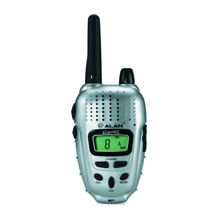
SmartComm SC-581 Series User manual

Page 1/11
INSTRUCTION MANUAL
SC- 580, SC- 581 series
UHF TRUNKING / CONVENTIONAL TRANSCEIVER
SC- 280, SC- 281 series
VHF TRUNKING / CONVENTIONAL TRANSCEIVER

Page 2/11
- FCC NOTICE -
SAFETY INFORMATION
This radio is restricted to occupational use, work related operations only where the radio
operator must have the knowledge to control its RF exposure conditions.
When the Push-to-Talk (PTT) button is pushed, the transceiver sends out radio frequency
(RF) signals. InAugust 1996, the Federal Communications Commission adopted RF
exposure guidelines with safety levels for hand-held wireless devices.
The device is authorized to operate at a duty factor not to exceed 50%.
WARNING
To maintain compliance with the FCC’s RF exposure guidelines, this transmitter and its
Antenna must maintain a separation distance of at least 1 inch (2.5 centimeters) from your
face and body.. Speak in a normal voice, with the antenna pointed up and away from the
face at the required separation distance.
NOTICE
This equipment has been tested and found to comply with the limits for a Class B digital
device, pursuant to Part 15 of the FCC Rules. These limits are designed to provide
reasonable protection against harmful interference in a reasonable installation. This
equipment generates, uses and can radiate radio frequency energy and, if not installed and
used in accordance with the instructions, may cause harmful interference to radio
communications. However, there is no guarantee that interference will not occur in a
particular installation. If this equipment does cause harmful interference to radio or
television reception, which can be determined by turning the equipment off and on, the
user is encouraged to try to correct the interference by one or more of the following
measures:
- Increase the separation between the equipment and receiver.
- Connect the equipment into an outlet on a circuit different from that to which the
receiver is connected.
- Consult the dealer or an experienced electronics technician for help.

Page 3/11
CONTENTS
GENERAL INFORMATION................................................................................ 4
SUPPLIED ACCESSORIES................................................................................................4
ACCESSORY ATTACHMENTS ......................................................................... 4
INSTALLING THE ANTENNA.........................................................................................4
INSTALLING / REMOVING THE BATTERY PACK........................................................5
INSTALLING THE BELT CLIP........................................................................................5
INSTALLING THE JACK COVER...................................................................................5
BATTERY SAFETY............................................................................................ 5
USING THE BATTERY PACK.............................................................................................6
INSTALLING / REMOVING THE BATTERY PACK............................................................6
BATTERY LIFE INDICATOR...............................................................................................6
CONTROL AND CONNECTIONS...................................................................... 7
POWER SWITCH / VOLUME CONTROL...........................................................................7
SYSTEM/GROUP CONTROL.............................................................................................7
TX/BUSY LED INDICATOR................................................................................................7
LCD (Liquid Crystal Display)............................................................................................7
H (HOME) KEY....................................................................................................................8
S (SCAN) KEY.....................................................................................................................8
F1 KEY.................................................................................................................................8
F2 KEY.................................................................................................................................8
10 KEY (SC- 580, SC-280 full key model only)................................................................8
PTT SWITCH.......................................................................................................................8
SHIFT (shift/key lock) KEY................................................................................................8
PROGRAMMABLE KEY FUNCTIONS...............................................................................9
ACCESSORY JACK............................................................................................................9
BATTERY PACK..................................................................................................................9
BATTERY LOCK.................................................................................................................9
ADJUST THE LCD CONTRAST.........................................................................................9
BASIC OPERATION........................................................................................ 10
LTR OPERATION..............................................................................................................10
CONVENTIONAL OPERATION........................................................................................10
EMERGENCY....................................................................................................................11
OPTION .............................................................................................................................11

Page 4/11
GENERAL INFORMATION
The SC-580 series and SC-280 series transceiver is a combination conventional and
trunking radio.
As the trunking radio, the radio is capable of operating on up to 32 trunking system, and
it can operate on E.F.Johnson LTR ® trunking protocol.
LTR® is a registered trademark of E. F. Johnson Company.
As the conventional radio, the radio is capable of operating on up to 250 channels.
Simplex (talk around) and semi-duplex operation are allowed on any system. The radio
contains an automatic power control that maintains constant RF power output, and
temperature compensating circuitry to maintain stable frequencies over varying
temperatures.
Note: Changes or modifications not expressly approved by Datron could void the User’s
authority to operate this equipment.
SUPPLIED ACCESSORIES
The following accessories
Flexible antenna ………………………1
Battery pack ………………………1
Belt clip ………………………1
Jack cover with screws ………………………1
ACCESSORY ATTACHMENTS
INSTALLING THE ANTENNA
Connect the supplied flexible antenna to the antenna connector.
Caution: Transmitting without theAntenna may damage the transceiver.
Do not hold by the antenna when carrying the transceiver.

Page 5/11
INSTALLING / REMOVING THE BATTERY PACK
1. Turn of the power off.
2. Remove the battery pack from the transceiver;
Pull the battery lock button and slide down the battery pack.
3. To insert the battery pack, slide up the battery pack.
INSTALLING THE BELT CLIP
If necessary, attach the belt clip using the two supplied screws.
INSTALLING THE JACK COVER
If you are not using the optional microphone and speaker, attach the jack cover.
BATTERY SAFETY
DANGER:
Do not disassemble or reconstruct battery!
Do not short battery pack terminals!
Do not incinerate or apply heat to the battery!
Do not use or leave the battery near fires, stoves, or other heat generators!
Do not immerse the battery in water or get it wet by other means!
Do not charge the battery near fires or under direct sunlight!
Do not pierce the battery with any object, strike it with an instrument, or step on it!
Do not jar or throw the battery!
Do not use the battery pack if it is damaged in any way!
Do not solder directly on to the battery!
Do not reverse the battery polarity!
Do not reverse charge or reverse connect the battery!
Do not touch a ruptured and leaking battery!

Page 6/11
WARNING: The battery pack should be charged only with exclusive charger. The use of any
other charger may cause injury and permanent damage to the battery.
Do not charge the battery for longer than the specified time!
Do not place the battery pack into a microwave or high pressure container!
Keep ruptured and leaking battery packs away from fire!
Follow charging instructions provided with the charger.
Do not use an abnormal battery!
Do not use the transceiver while it is in the charger!
Keep the battery contacts clean.
Do not charge the battery when the ambient temperature is less than +50 degrees
Fahrenheit / +10 degrees Celsius or above +104 degrees Fahrenheit / +40 degrees Celsius.
USING THE BATTERY PACK
Charge the battery pack before using it.
To keep the battery discharge at a minimum, remove the battery pack from the transceiver
when it is not in use.
Store the battery pack in a cool place to maximize storage life. Since batteries are subject to
self discharge, avoid high storage temperatures; this will cause large self-discharge rates.
After extended storage, a full recharge is recommended.
INSTALLING / REMOVING THE BATTERY PACK
1. Turn of the power off.
2. Remove the battery pack from the transceiver;
Pull the battery lock button and slide down the battery pack.
3. To insert the battery pack, slide up the battery pack.
BATTERY LIFE INDICATOR
Battery life is indicated by the battery icon in the LCD. The transceiver must be recharged
when the low battery life indicator (battery empty mark) is still displayed.
The transceiver will be unavailable when the low battery life warning is displayed”No
Battery”.

Page 7/11
CONTROL AND CONNECTIONS
POWER SWITCH / VOLUME CONTROL
Turns the transceiver on and off, and adjusts the volume.
SYSTEM/GROUP CONTROL
In the conventional and LTR® trunking system, it selects either F (functional position) or one
of 15 Systems/Groups.
TX/BUSY LED INDICATOR
Lights red during transmission, green during reception or when busy.
LCD (Liquid Crystal Display)
Indicates Monitor mode, System and Group number, alphanumeric description, in-range,
scan memory, telephone interconnect, phone numbers, key lock and remaining battery life.

Page 8/11
H (HOME) KEY
In the conventional and LTR® trunking system, it returns the radio working system to the
programmed HOME system and group.
This key also activates the DTMF “A”tone during transmission.
S (SCAN) KEY
Pressing this key for longer than 2 seconds changes the radio operation between the
conventional / LTR® trunking system.
In the conventional and LTR® trunking system, when the SYSTEM/GROUP control is set to
the “F”position, the S (scan) key initiates scanning and is used for storing channels in scan
memory.
This key also activates the DTMF “B”tone during transmission.
F1 KEY
In the conventional and LTR® trunking system, when the SYSTEM/GROUP control is set to
the “F”position, pressing this key decreases the Group number, or decreases the System
number in the shift mode.
This key also activates the DTMF “C”tone during transmission.
F2 KEY
In the conventional and LTR® trunking system, when the SYSTEM/GROUP control is set to
the “F”position, pressing this key increases the Group number, or increases the System
number in the shift mode.
This key also activates the DTMF “D”tone during transmission.
10 KEY (SC- 580, SC-280 full key model only)
Press the keys on the 10 keypad to make DTMF calls or to activate programmable
functions.
PTT SWITCH
Enables transmit mode.
SHIFT (shift/key lock) KEY
Enables or disables the SHIFT mode. Pressing this key for the longer than 2seconds will
enable or disable keypad operation.

Page 9/11
PROGRAMMABLE KEY FUNCTIONS
The following key functions can be programmed by your dealer. Each function can be
programmed to any key. Refer to your dealer for programming and operating instructions.
Programmable key
Key function
AUX SHIFT+AUX
H SHIFT+H S SHIFT+S
A/D - - - O - O
TA - - - O - O
TRANSPOND
- - - O - O
PHONE O O - O - O
MONITOR O O - O - O
H/L O O - O - O
NET O O - O - O
OPTION - O - O - O
O: can be programmed, -: can not be programmed.
ACCESSORY JACK
Interface for connecting an external speaker and microphone.
BATTERY PACK
Provides DC power supply to the transceiver.
BATTERY LOCK
To detach the battery pack, turn off the power, slide the lock lever to open, and slide down
the battery pack and remove.
ADJUST THE LCD CONTRAST
The LCD contrast can be adjusted.
1. Turn off power, off.
2. Hold down the SHIFT key and turn the power on.
(After releasing the SHIFT key, it will be displayed “CONTRAST”.)
3. To adjust the contrast, hold down the PTT switch and turn the volume knob.
4. Release the PTT switch, and turn the power off.

Page 10/11
BASIC OPERATION
1. Turn the power switch / volume control clockwise to switch the transceiver on.
Turn the Power switch / volume control counterclockwise to switch the transceiver off.
2. Rotate the power switch / volume control to adjust the volume.
Clockwise increase the volume.
Counter clockwise decrease the volume.
LTR OPERATION
Push the key, or rotate System / Group control to select the desired system channel and talk
group.
Note: Systems, groups and their functions are programmed by your dealer.
RECEIVING : When a call is received, the transceiver will automatically change to correct
group and you will hear the call.
TRANSMITTING : Press and hold the PTT switch and speaking into the microphone.
Release the PTT switch to receive.
CONVENTIONAL OPERATION
Push the key, or rotate System / Group control to select the desired system channel and talk
group.
Note: Systems, groups and their functions are programmed by your dealer.
RECEIVING : When you hear the caller’s voice, adjust the volume.
TRANSMITTING : Press the programmable Monitor key. Check the channel.
If Channel is busy, wait until it becomes free.
Press and hold the PTT switch and speaking into the microphone.
Release the PTT switch to receive.

Page 11/11
EMERGENCY
When *(Orange) key is pushed more than 1.5sec, the DTMF emergency signal is
automatically transmitted.
Note: An emergency functions are programmed by your dealer.
To exit emergency mode, press and hold *(Orange) key again or turn off the power switch.
OPTION
When the programmed key is pushed, the Option function can be used.
Function on : “▼”appears on the display.
Function off : “▼”disappears on the display.
When the optional board (Scrambler unit or Man Down unit) is installed, the Option function
can be used.
-Scrambler -
The voice scrambler function provides private communication between stations.
-Man Down-
The man down function transmits emergency signal after the man down is activated for a
period exceeding the specified time.
Note: Option function is programmed by your dealer. Ask your dealer for Option board
details.
This manual suits for next models
3
Table of contents
Other SmartComm Transceiver manuals
