Smartec SPB Series User manual

SPB Series
DIN rail mounting switching mode power supply
● DIN rail type and fixing screw type mountings
● Built-in overcurrent protection, output short circuit
protection, overheat and over voltage limit protection
circuit (S B-120)
● Built-in power factor correction circuit(S B-120/240)
● Low-voltage LED indicator
● Slim-type size (S B-060: W36×H100×L110mm)
● Minimizes noise and ripple
● Improves user safety with terminal cover
● Designed to minimize heat
● Output power : 60W, 120W, 240W
● Output voltage: 12VDC, 24VDC, 48VDC
Ordering information
Specifications
Features
Item
Output power
Output voltage
SPB 060 2
12 12VDC
24 24VDC
48 48VDC
060 60W
120 120W
240 240W
S B Switching Mode ower Supply
SPB-060
Series
SPB-120
Series
SPB-2 0
Series
Please read “Caution for your safety” in operation
manual before using.
Over-heating protection
If the inner temperature of the switching element is around 140℃ by overheat, it stops switching operation and becomes
open state. Output voltage is not output.
Model SPB-060-12 SPB-060-2 SPB-120-2 SPB-2 0-12 SPB-2 0-2 SPB-2 0- 8
Output power 60W 120W 240W
Input
Voltage 100-240VAC(85-264VAC)
Frequency 50/60Hz
Efficiency※1 Min. 75% Min. 80% Min. 86% Min. 88%
ower factor※1
-
Min. 0.9
Current consumption
※1Max. 1.6A Max. 1.9A Max. 3.8A
ower factor correction circuit
-
Built-in
Output
Voltage 12VDC 24VDC 12VDC 24VDC 48VDC
Current 5A 2.5A 5A 20A 10A 5A
Voltage adjustment range
※2Max. ±5%
Input variation※3Max. ±0.5%
Load variation※1Max. ±1% Max. ±1.5%
Ripple※1Max. ±1% Max. ±3% Max. 1.5% Max. ±1%
Start-up time※1Max. 600ms Max. 1000ms
Hold time※1 Min. 10ms Min. 20ms
rotection
Inrush current protection Max. 25A (100VAC), Max. 40A(240VAC) Max. 50A(100VAC), Max. 50A(240VAC)
Output over current protection
※
Min. 105%
Output over voltage protection
-
30.0V ±10% 16.0V ±10% 30.0V ±10% 58.0V ±10%
Output short-circuit protection
Max. 10ms
Output low-voltage indicate
9.6V±10% 20.0V±10% 10.0V±10% 20.0V±10% 43.0V±10%
Output indicator Green LED
※1: It is for the rated input voltage 100-240VAC, and 100% load.
※2: Adjusting voltage by the output adjuster (V.ADJ), it is changed the below voltage adjustment range(±5%).
※3: It is for the rated input voltage 100-240VAC(85-264VAC), and 100% load.
※4: It is for the rated input voltage 100-240VAC.
Tel:
11 4425-5103 Tel: 11 2759-8613 Internet: www.smartec-automacao.com.br E-mail:
smartec@smartec-automacao.com.br
Tel:
11 4425-5103 Tel: 11 2759-8613 Internet: www.smartec-automacao.com.br E-mail:
smartec@smartec-automacao.com.br
(A)
Photo
electric
sensor
(B)
Fiber
optic
sensor
(C)
Door/Area
sensor
(D)
Proximity
sensor
(E)
Pressure
sensor
(F)
Rotary
encoder
(G)
Connector/
Socket
(H)
Temp.
controller
(I)
SSR/
Power
controller
(J)
Counter
(K)
Timer
(L)
Panel
meter
(M)
Tacho/
Speed/ Pulse
meter
(N)
Display
unit
(O)
Sensor
controller
(P)
Switching
mode power
supply
(Q)
Stepper
motor&
Driver&Controller
(R)
Graphic/
Logic
panel
(S)
Field
network
device
(T)
Software
(U)
Other
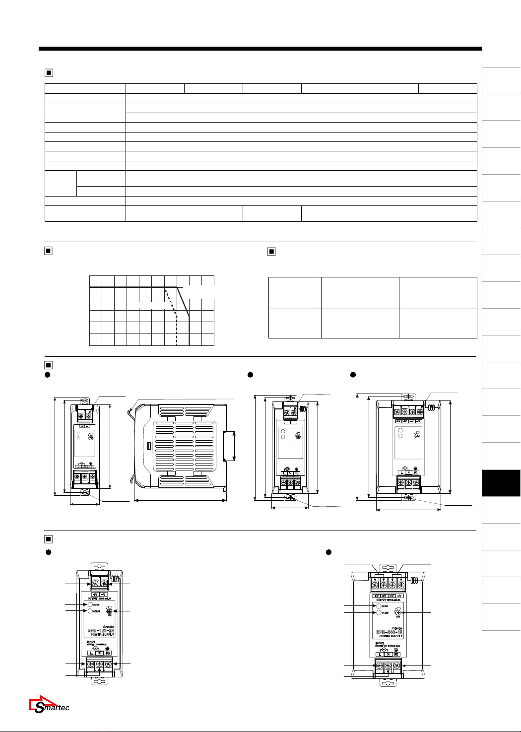
DIN rail Mounting Type Switching Mode Power Supply
Dimensions
Recommended power input
voltage wire for model
Output deterating curve by
ambient temperature
Recommended
power input
voltage wire
AWG21-19 AWG18-16
Model
S B-060-12
S B-060-24
S B-120-24
S B-240-12
S B-240-24
S B-240-48
(unit: mm)
SPB-060 Series SPB-120 Series
117
36 2-Ø4.2
5-M3.5
110
100
SPB-2 0 Series
110
35.4
※Side sizes are same as
S B-060/120 /240 Series.
2-Ø4.2
5-M3.5
50
132
125
115
+V -V
When opening terminal cover
125
115
132
7-M3.5
80 2-Ø4.2
Model SPB-060-12 SPB-060-2 SPB-120-2 SPB-2 0-12 SPB-2 0-2 SPB-2 0- 8
Insulation resistance Min. 100MΩ(at 500VDC megger between all input terminals and output terminals)
Dielectric strength 3000VAC 50/60Hz for 1 min. (between all input terminals and output terminals)
1500VAC 50/60Hz for 1 min. (between all input terminals and F.G.)
Vibration 0.75mm amplitude at frequency of 10 to 55 Hz (for 1 min.) in each of X, Y, Z directions for 2 hour
Shock 300m/s² (approx. 30G) in each of X, Y, Z directions for 3 times
EMS Conforms to EN61000-6-2
EMI Conforms to EN61000-6-4
Safety IEC60950, IEC50178
Environ-
ment
Ambient
temperature -10 to 50℃, storage: -25 to 65℃
Ambient humidity
25 to 85%RH, storage: 25 to 90%RH
rotection I 20(IEC standard)
Unit weight※5Approx. 347g(approx. 274g) Approx. 570g
(approx. 466g) Approx. 866g(approx. 736g)
※5: The weight is with packaging and the weight in parentheses is only unit weight.
※Environment is rated at no freezing or condensation.
SPB-060/120 Series SPB-2 0 Series
1. Output power [+V] terminal
2. Output power [-V] terminal
3. Output(DC ON) indicator(green)
. Output low voltage (DC LOW)
indicator(red)
5. Output voltage adjuster(V.ADJ)
6. Input power [L] terminal
7. Input power [N] terminal
8. Frame ground [F.G.] terminal
2
5
8
1
3
6
7
2
5
8
3
6
7
1
Part descriptions
Forced air cooling
(air volume:0.878m3/min)
Natural cooling
120
100
80
Load
ratio
(%)
60
40
20
0
-10 0 10 20 30 40 50 60 70 80 90
Ambient
temperature
(℃)
Specifications
Tel:
11 4425-5103 Tel: 11 2759-8613 Internet: www.smartec-automacao.com.br E-mail:
smartec@smartec-automacao.com.br
Tel:
11 4425-5103 Tel: 11 2759-8613 Internet: www.smartec-automacao.com.br E-mail:
smartec@smartec-automacao.com.br

SPB Series
Caution for operating
This product does not have the function for parallel or series operation.
The output current must be used within the rated specification.
If over current is applied to the product, over current protection is operating.
It causes shorten the life cycle of the product.
The output voltage must be used within the rated output specification.
For the product, which has the control function for over-voltage, if making the output voltage adjuster(V.ADJ) to over
rated voltage, the function starts to work.
This product has the function of over-heating protection.
The over-heating protection operates when the product has over-heating condition.
The product normally operates if the load is removed for over 5 minutes.
In case of the S B-060, it does not have the harmonics suppression and power factor improvement circuit.
To improve harmonics suppression and power factor, install the additional device.
In case of the S B-060, it uses condenser rectification, and power factor is within 0.4 to 0.6 range. To use a cabinet
panel or a electric transformer, select input power capacity of this product as below formula.
This product is provided with a noise filter, but noise is variable according to operating conditions such as installation
environment and wiring.
When the inner fuse is damaged, replace the fuse of same specification.
Caution for using
Input apparent power[VA] = Output active power[W]
ower factor×Efficiency
ⓑ
ⓐ
ⓒ
Rail hook
Min. 30mm
※When mounting the power
supply on the rail, place the
item at least 30mm above
from the floor to remove it
easily.
2-M4
Installation
DIN rail mounting
● To mount the power supply on the rail,
First put the power supply on the part ⓐ of the rail
and then press it for the direction ⓑ.
Panel mounting
● When there is no rail
This power supply has two hooks. If pushing these at the
arrows direction as below figure, you can mount this power
supply with general bolts.
● To remove the power supply on the rail
First put a screw driver into the part ⓒ and push it
downward.
Tel:
11 4425-5103 Tel: 11 2759-8613 Internet: www.smartec-automacao.com.br E-mail:
smartec@smartec-automacao.com.br
Tel:
11 4425-5103 Tel: 11 2759-8613 Internet: www.smartec-automacao.com.br E-mail:
smartec@smartec-automacao.com.br

(A)
Photo
electric
sensor
(B)
Fiber
optic
sensor
(C)
Door/Area
sensor
(D)
Proximity
sensor
(E)
Pressure
sensor
(F)
Rotary
encoder
(G)
Connector/
Socket
(H)
Temp.
controller
(I)
SSR/
Power
controller
(J)
Counter
(K)
Timer
(L)
Panel
meter
(M)
Tacho/
Speed/ Pulse
meter
(N)
Display
unit
(O)
Sensor
controller
(P)
Switching
mode power
supply
(Q)
Stepper
motor&
Driver&Controller
(R)
Graphic/
Logic
panel
(S)
Field
network
device
(T)
Software
(U)
Other
DIN rail Mounting Type Switching Mode Power Supply
Dielectric or insulation resistance test when this unit is installed in the control panel.
Separate the unit completely from a control panel circuit.
Short all terminals of the unit.
Caution for connecting the input power terminal
Connect input line (AC) to the input terminal correctly.
When you connect this to the other terminal, it may cause damage to the power supply.
Do not use this unit at below places.
lace where there are severe vibration or impact.
lace where strong alkalis or acids are used.
lace where there is direct ray of the sun.
lace where strong magnetic field or electric noise are generated.
Installation environment
It shall be used indoor
Altitude max. 2000m
ollution Degree 2
Installation Category II
- Natural cooling mounting
When installing more than two power supplies, min.
20mm distance is required to radiate heat effectively.
Assure min. 75mm distance of the upper or the lower
product and mount the products as following figure.
- Forced air cooling mounting
For effective heat radiation, assure min. 75mm
distance of the upper and lower product to flow
air as the below figure. Install a fan which min.
air volume is 0.878m3/min within 50mm from the
product to maintain the reliability of the product.
Air flow Min.
75mm
Min.
75mm
Min. 20mm
Air flow
Air flow
Min. 75mm
Min. 75mm
Min. 50mm
Caution for using
Caution for mounting
Mount this product on the surface of metal panel vertically for the reliability.
lease mount this product at a well-ventilated place in order to increase the heat radiation efficiency.
Effective mounting
Tel:
11 4425-5103 Tel: 11 2759-8613 Internet: www.smartec-automacao.com.br E-mail:
smartec@smartec-automacao.com.br
Tel:
11 4425-5103 Tel: 11 2759-8613 Internet: www.smartec-automacao.com.br E-mail:
smartec@smartec-automacao.com.br
This manual suits for next models
3
Popular Power Supply manuals by other brands


LOVATO ELECTRIC
LOVATO ELECTRIC ATL DPS1 operating manual

SIGLENT
SIGLENT SPD3303C Series quick start

Pertronic
Pertronic FAAST AUX24V-1.3A Installation note

Cisco
Cisco IW-PWRADPT-MFIT4P installation guide

National Instruments
National Instruments RMX-410 Series user manual

PowerBox Systems
PowerBox Systems EVOLUTION instruction manual


