EnerSys alpha LPS36 Quick start guide

LPS36
Line Power System
Technical Guide: 0120011-J0
Effective: 07/2020


Cordex HP LPS36/Compact
-48Vdc to +/-190Vdc Line Power System
NOTE:
Photographs contained in this manual are for illustrative purposes only. These photo-
graphs may not match your installation.
NOTE:
Operator is cautioned to review the drawings and illustrations contained in this manual
before proceeding. If there are questions regarding the safe operation of this powering
system, contact Alpha and Outback Energy GmbH or your nearest AOE representative.
NOTE:
AOE shall not be held liable for any damage or injury involving its enclosures, power
supplies, generators, batteries, or other hardware if used or operated in any manner or
subject to any condition inconsistent with its intended purpose, or if installed or oper-
ated in an unapproved manner, or improperly maintained.
For technical support, contact Alpha and Outback Energy GmbH:
Tel: +49 9122 79889 0
Mail: [email protected]
Copyright
Copyright © 2019 Alpha Technologies Ltd. All rights reserved. Alpha is a registered trademark of Alpha Technolo-
gies.
No part of this documentation shall be reproduced, stored in a retrieval system, translated, transcribed, or transmit-
ted in any form or by any means manual, electric, electronic, electromechanical, chemical, optical, or otherwise
without prior explicit written permission from Alpha Technologies.
This document, the software it describes, and the information and know-how they contain constitute the proprietary,
confidential and valuable trade secret information of Alpha Technologies, and may not be used for any unauthorized
purpose, or disclosed toothers without the prior written permission ofAlpha Technologies.
The material contained in this document is for information only and is subject to change without notice. While
reasonable efforts have been made in the preparation of this document to assure its accuracy, Alpha Technologies
assumes no liability resulting from errors or omissions in this document, or from the use of the information contained
herein. Alpha Technologies reserves the right to make changes in the product design without reservation and with-
out notification to its users.


3
0120011-J0 Rev M
Table of Contents
1. Safety �����������������������������������������������������������������������������������������������������������������������������������7
1.1 Safety Symbols .......................................................................................................................... 7
1.2 General Warning and Cautions.................................................................................................. 7
1.3 Mechanical Safety...................................................................................................................... 7
1.4 Electrical Safety ......................................................................................................................... 8
2. Product Overview................................................................................................................10
2.1 Product Part Numbers ..............................................................................................................11
2.2 Block Diagram—Three Shelves and a Fan Tray (19" and 23")................................................ 12
3. Product Specications ........................................................................................................13
4. Features..............................................................................................................................15
4.1 Converter Modules................................................................................................................... 15
4.2 LPS36 System Features (19"/23") ........................................................................................... 16
4.3 LPS Compact System Features (6") ........................................................................................ 20
5. Site Evaluation and Pre-Installation....................................................................................22
5.1 Pre-Installation Requirements.................................................................................................. 22
5.2 Packing Materials..................................................................................................................... 23
6. LPS36 System Installation..................................................................................................24
6.1 General Instructions................................................................................................................. 24
6.2 Safety Precautions................................................................................................................... 24
6.3 Tools Required ......................................................................................................................... 25
6.4 Thermal Management.............................................................................................................. 26
6.5 LPS36 Set Up: 19" and 23" Systems....................................................................................... 29
6.6 LPS Compact Set Up: 6" Systems........................................................................................... 34
6.7 Making Load Connections ....................................................................................................... 42
6.8 System Startup with CXCI+ Controller..................................................................................... 44
6.9 System Startup with the CXCI HP Controller........................................................................... 54

0120011-J0 Rev M
4
7. Maintenance and Troubleshooting......................................................................................61
7.1 Troubleshooting Converter Status LEDs.................................................................................. 61
7.2 Fan Filter Maintenance and Installation (19/23" only).............................................................. 63
7.3 Replacing the Fan Tray............................................................................................................ 65
7.4 Replacing a Converter (19"/23") .............................................................................................. 66
7.5 Replacing the Controller (19"/23" only).................................................................................... 66
7.6 Replacing an Alarm Relay Module (19"/23" only) .................................................................... 67
7.7 Spare Parts .............................................................................................................................. 69
8. Warranty Statement and Service Information .....................................................................70
8.1 Technical Support .................................................................................................................... 70
8.2 Warranty Statement ................................................................................................................. 70
8.3 Product Warranty ..................................................................................................................... 70
8.4 Battery Warranty ...................................................................................................................... 70
8.5 Warranty Claims....................................................................................................................... 70
8.6 Service Information .................................................................................................................. 70
9. Acronyms and Denitions ...................................................................................................71
10. Certication.......................................................................................................................72

5
0120011-J0 Rev M
List of Figures
Figure 1 — LPS36 shelf (19" shown).............................................................................................. 10
Figure 2 — LPS36 Compact (6" shown), cable length not to scale ................................................ 10
Figure 3 — LPS36 shelf (19" shown).............................................................................................. 16
Figure 4 — CXCI HP controller front panel..................................................................................... 16
Figure 5 — Cordex CXCI+ controller front panel ............................................................................ 17
Figure 6 — Shelf Connections ........................................................................................................ 18
Figure 7 — Shelf Alarm LEDs ......................................................................................................... 18
Figure 8 — Fan and Bae Tray Rack, mounted (19" shown)......................................................... 19
Figure 9 — Shelf Connections ........................................................................................................ 20
Figure 10 — DC input cable kit accessory (ordered separately, PN 8700870-001) ....................... 21
Figure 11 — Fan tray ...................................................................................................................... 21
Figure 12 — Natural Convection 19"/23" Systems ......................................................................... 26
Figure 13 — Output Power Derating Curve .................................................................................... 27
Figure 14 — Multi-shelf System Mounting ...................................................................................... 27
Figure 15 — LPS36 Compact Shelf with Fan Tray ......................................................................... 28
Figure 16 — Minimum Air Flow....................................................................................................... 28
Figure 17 — Locations for protective earthing terminals for chassis ground (LPS36 side view) .... 30
Figure 18 — DC input connections (19") ........................................................................................ 30
Figure 19 — DC input wiring connections....................................................................................... 31
Figure 20 — CAN and fan connections on the shelf interface panel (for reference only)............... 31
Figure 21 — CAN OUT terminator.................................................................................................. 32
Figure 22 — CAN Bus cabling ........................................................................................................ 32
Figure 23 — Fan tray connections.................................................................................................. 32
Figure 24 — Converter shelf alarm relays ...................................................................................... 33
Figure 25 — Fan Tray Alarm Relay................................................................................................. 33
Figure 26 — Rack Mount Bracket Assembly (either side, based on installation)............................ 34
Figure 27 — Rack Mount (left side shown)..................................................................................... 35
Figure 28 — Rack Mount, Left side with Fan Tray.......................................................................... 35
Figure 29 — Right Side Mount, with Fan Tray ................................................................................ 36

0120011-J0 Rev M
6
Figure 30 — Rack Mount Left Side, LPS modules upside down .................................................... 36
Figure 31 — Mounted Sideways (front of unit) ............................................................................... 37
Figure 32 — Mounted Sideways (back of unit) ............................................................................... 37
Figure 33 — Locations for Chassis Ground (LPS36 Compact, side view) ..................................... 39
Figure 34 — DC Input Connections ............................................................................................... 40
Figure 35 — DC Input Cable Kit Accessory .................................................................................... 40
Figure 36 — PIN Assignment Table ................................................................................................ 41
Figure 37 — CAN Connection ........................................................................................................ 41
Figure 38 — Connector Pinouts ..................................................................................................... 42
Figure 39 — Live Graphical View ................................................................................................... 45
Figure 40 — Live Table View .......................................................................................................... 45
Figure 41 — Channel Information for Position 6............................................................................. 46
Figure 42 — Grouping LPS Channels ............................................................................................ 47
Figure 43 — LPS Channel Custom Text ......................................................................................... 48
Figure 44 — LPS Alarm Highlighting .............................................................................................. 49
Figure 45 — Viewing LPS Alarms................................................................................................... 49
Figure 46 — Conguring LPS Alarms ............................................................................................. 50
Figure 47 — Fan Tray Live Status .................................................................................................. 50
Figure 48 — Conguring a Custom Alarm ...................................................................................... 51
Figure 49 — Equation Editor for Conguring a Fan Fail Alarm....................................................... 51
Figure 50 — Fan Fail Alarm ............................................................................................................ 51
Figure 51 — Manage Editable Text Files ........................................................................................ 52
Figure 52 — Custom Name Change............................................................................................... 52
Figure 53 — Line Power System Wizard ........................................................................................ 55
Figure 54 — Quick Reference: Congure a Line Power System.................................................... 55

7
0120011-J0 Rev M
1� Safety
SAVE THESE INSTRUCTIONS: This manual contains important safety instructions that must be followed
during the installation, servicing, and maintenance of the product. Keep it in a safe place. Review the drawings
and illustrations contained in this manual before proceeding. If there are any questions regarding the safe
installation or operation of this product, contact Alpha Technologies or the nearest Alpha representative.
1.1 Safety Symbols
To reduce the risk of injury or death, and to ensure the continued safe operation of this product, the following
symbols have been placed throughout this manual. Where these symbols appear, use extra care and attention.
NOTE:
A NOTE provides additional information to help complete a specific task or procedure.
Notes are designated with a checkmark, the word NOTE, and a rule beneath which the
information appears
CAUTION!
CAUTION indicates safety information intended to PREVENT DAMAGE to material or
equipment. Cautions are designated with a yellow warning triangle, the word CAUTION,
and a rule beneath which the information appears.
WARNING!
WARNING presents safety information to PREVENT INJURY OR DEATH to personnel.
Warnings are indicated by a shock hazard icon, the word WARNING, and a rule beneath
which the information appears.
HOT!
The use of HOT presents safety information to PREVENT BURNS to the technician or
user.
1.2 General Warning and Cautions
WARNING!
This system is designed to be installed in a restricted access location that is
inaccessible to the general public.
1.3 Mechanical Safety
CAUTION!
Do not disassemble the product – call our qualified service centers for servicing.
Incorrect reassembling may result in a risk of electrical shock or fire.
Do not operate the product if it has received a sharp blow, it has been dropped, or
otherwise damaged in any way – return it to a qualified service center for repair.

0120011-J0 Rev M
8
LPR48-150
LPS36
Channel 1
T1
R1
≤75W
≤75W
LPS36
Channel 2
CONVERTER #1
CONVERTER #2
RADIO 100W
Load
T2
R2
+190V
-190V
+190V
-190V
Input A
Input B
LPR48-150
LPS36
Channel 1
T1
R1
≤75W
≤75W
LPS36
Channel 2
CONVERTER #1
CONVERTER #2
RADIO 100W
Load
T2
R2
+190V
-190V
+190V
-190V
Input A
Input B
Bridging circuits
1�4 Electrical Safety
Before working with any live battery or power system, follow these precautions:
a. Remove all metallic jewelry, such as watches, rings, metal rimmed glasses, or necklaces.
b. Wear safety glasses with side shields at all times during the installation.
c. Use OSHA approved insulated hand tools. Do not rest tools on top of batteries.
WARNING!
The DC input to the modules (and the converter system) – though not dangerous in volt-
age – has a high short circuit current capacity that may cause severe burns and electri-
cal arcing.
The DC output is a potentially dangerous voltage. Do not touch the output connections
when under power. Ensure that power has been removed from the outputs before work-
ing on them.
NOTE:
RFT-V output circuit configuration – bridged operation (not permitted)
The DC output is classified as an RFT-V circuit with a maximum rated power of
100W per channel. Paralleling of RFT-V circuits over multiple telecommunications
wires for the purpose of delivering power in excess of 100VA to a single load circuit
is not permitted. Refer to UL/CSA 60950-1 Section 6.2.1 for details.
RFT-V output circuit configuration – normal operation (permitted)

9
0120011-J0 Rev M
WARNING!
Lethal voltages are present within the power system. Always assume that an electrical
connection or conductor is energized. Check the circuit with a voltmeter with respect to
the grounded portion of the enclosure (both AC and DC) before performing any installa-
tion or removal procedure.
• Do not work alone under hazardous conditions.
• A licensed electrician is required to install permanently wired equipment. Hazardous voltages are present at
the input of power systems. Ensure that the utility power is disconnected and locked out before performing
any installation or removal procedure.
• Ensure that no liquids or wet clothes come into contact with internal components.
• Hazardous electrically live parts inside this unit are energized from the batteries even when the AC input
power is disconnected.
• The enclosure which contains the DC or AC power system along with customer installed radios must remain
locked at all times, except when authorized service personnel are present.
• Always assume electrical connections or conductors are live. Turn off all circuit breakers and double-check
with a voltmeter before performing installation or maintenance.
• Place a warning label on the utility panel to warn emergency personnel that a reserve battery source is pres-
ent which will power the loads in a power outage condition or if the AC disconnect breaker is turned off.
• At high ambient temperature conditions, the internal temperature can be hot so use caution when touching
the equipment.
0120011-J0 Rev M
10
2� Product Overview
The LPS36 is a modular DC to DC up-converter system designed for distributed power communications applica-
tions using +/- 190Vdc (RFT-V circuit) over existing copper network.
Using switched mode technology, the LPS36 quad output converter module provides outstanding efficiency in a
compact design. Applications include powering sealed DSLAM’s, Distribution Point Units (DPU) as well as Optical
Network Terminals (ONT) in Fiber to the Home Networks (FTTH). Each LPS36 converter module contains four iso-
lated DC-DC converters, up to 100 Watt maximum. Converter modules are ordered separately at time of ordering or
later after the converter system has been installed. Blank plates can be ordered separately for empty slots.
• High efficiency >92% for increased operating expenses (OPEX) savings and reduced carbon footprint
• High temperature tolerance for installation in Central Office (CO) or harsh outside plant (OSP) cabinet environ-
ments
• Industry leading power density enabling up to 48 channels in a compact 2RU footprint
• High reliability convection-cooled design with optional fan tray
• Cordex CXCI series of system controllers provide advanced remote web based monitoring and control features
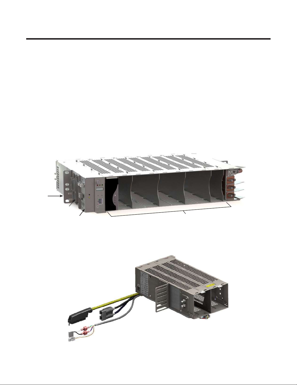
Figure 1 — LPS36 shelf (19" shown)
CXCI+ Converter slots #1-9
Mid mount
brackets
Load connectors
Front input
connections
Shelf
interface
panel
Rear input connections
(not shown)
#9
#1
Figure 2 — LPS36 Compact (6" shown), cable length not to scale

11
0120011-J0 Rev M
The 19" and 23"LPS36 systems consist of one or more converter modules and a CXCI+ controller installed in a
common shelf. A 19" shelf can have up to 9 modules, and a 23" shelf up to 12. All connections are front access. In-
put connections can be made at the rear of the unit as well. External connections are available at the shelf interface
panel for alarm interfaces.
The LPS36 Compact packs maximum power into minimum space, but doesn’t compromise on features. The shelf
provides up to 16 line powering channels in the compact 2RU x 6” x 12” form. Standard system features include
major and minor alarms for monitoring, connectorized cable output and one side mounting. This product is particu-
larly suitable for remote OSP power cabinets where free rack space is tight or non-existent. With a six inch width
and a single side bracket, it can be easily mounted to the side of a rack support post without using up valuable rack
space.
Alpha’s LPS36 modular DC to DC converter systems incorporate a full range of standard features, including cur-
rent limiting and individual ground fault interrupt for each circuit. Particular emphasis is placed on recognizing a
fault condition and shutting down the circuit as quickly as possible to ensure the highest level of personnel safety.
Compliance with GR-1089-CORE - Class A2 provides the ability to work on the equipment while powered, which
significantly reduces the administrative and labeling requirements and overheads for the high voltage wiring.
2�1 Product Part Numbers
Product Part number
19" Shelf - 9 modules 0300055-001
19" Fan Tray 0300055-002
19" Bae 0300055-003
23" Shelf - 12 modules 0300090-001
23" Fan Tray 0300090-002
23" Bae 0300090-003
Input Cover Kit (19/23") 0380249-001
Alarm Cable Kit (19/23") 8700649-001
6" Shelf - 4 modules 0300189-004
6" Fan Tray 0300189-002
6" Input Lug Kit (18") 8700870-001
CXCI+ Controller 7400232-001
CXCI HP Controller 0180053-001
Converter Modules 0120011-001
Blanking Plate Kit (quantity 2) 0380070-001
0120011-J0 Rev M
12
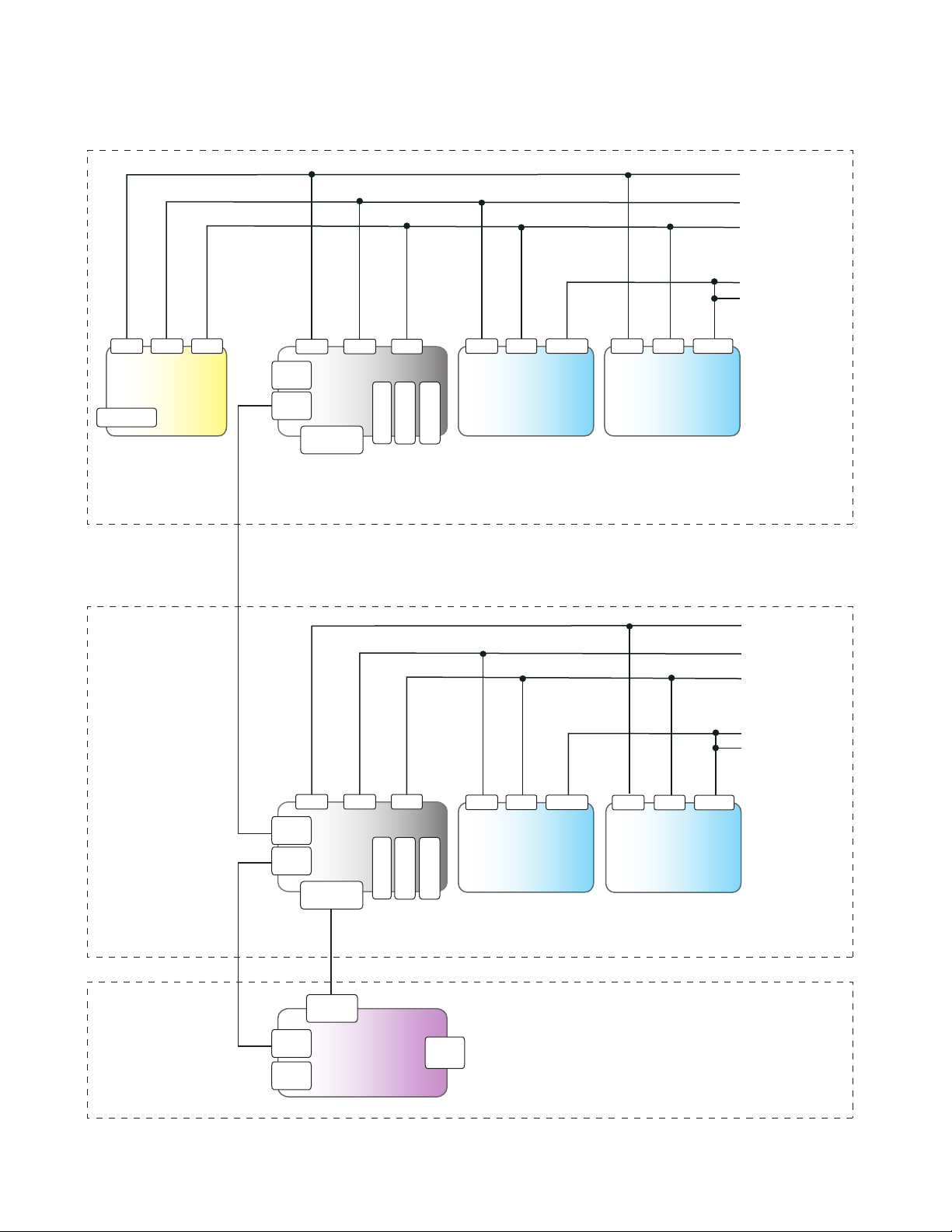
2�2 Block Diagram—Three Shelves and a Fan Tray (19" and 23")
CXCI+ Controller
Form C
contacts
SHELF 1 with CONTROLLER
Common RTN
OSP cable +/-190V lines
RJ21-J2
RJ21-J1
-48V Input A
-48V Input B
Common RTN
-48V Input A
-48V Input B
RTN
-48B -48A
CAN
out FAN
ALM
Fan tray
Fan
PWR in
SHELF 2 (not shown for clarity)
SHELF 3
FAN TRAY
Ethernet
Form C
contacts
Form C
contacts
CAN
in
-48A VOUT
DC-DC
power modules
slots 1- 5 (19")
slots 1 - 6 (23")
RTN
VOUT
-48B
DC-DC
power modules
slots 6-9 (19")
slots 7-12 (23")
RTN
VOUT
-48B
DC-DC
power modules
slots 6-9 (19")
slots 7-12 (23")
RTN
-48A VOUT
DC-DC
power modules
slots 1- 5 (19")
slots 1 - 6 (23")
RTN
OSP cable +/-190V lines
RJ21-J2
RJ21-J1
Interface Board
Shelf ID
-48B -48A
MAJOR
MINOR
CAN
out
CAN
in
RTN
Fan
PWR out
Interface Board
Shelf ID
-48B -48A
MAJOR
MINOR
CAN
out
CAN
in
RTN
Fan
PWR out

13
0120011-J0 Rev M
3� Product Specifications
Electrical
Input Voltage: -40 to -60Vdc
Recommended Breaker:
6" Shelf: 50A per feed
19" Shelf: 70A per feed
23" Shelf: 80A per feed
Recommended Cable Size: As per NEC 2014, Minimum #6 AWG (16mm2) copper rated for 90˚C or #4 (25mm2) rated
for 75˚C
Output Voltage: ±190Vdc (RFT-V)
Power: 96W nominal per output, >92W for worst case conditions (4 outputs per module)
>92%
Regulation: <2% no load to full load
<1% line
Output Noise:
Wide Band: <500mVRMS (10kHz to 10MHz)
<2.5V p-p (10kHz to 100MHz)
Acoustic: <60dBa @ 1m (3ft), 55˚C
Connections (19/23"):
Input: HOT: 2x sets, 1/4" holes on 5/8" centers
RTN: 2x sets, 1/4" holes on 5/8" centers
Output: Two 50-pin amp-champ style connector
Alarm Two 5-OIN terminal bloacks
Connections (6"):
Input: Anderson style connector
Output: One 50-pin amp-champ style connector
Alarm TE style connector
Quad Output Power Module (#0120011-001)
Dimensions (HxWxD): 386mm x 35mm x 283mm (3.4in x 1.4in x 11.1in)
Weight: 0.61kg (1.4lbs)
19" Shelf - 9 Modules (#0300055-001)
Dimensions (HxWxD): 88mm x 435mm x 311mm (3.5in x 17.1in x 12.25in)
Weight: 5.45kg (12lbs)
23" Shelf - 12 Modules (#0300090-001)
Dimensions (HxWxD): 88mm x 536mm x 311mm (3.5in x 21.1in x 12.25in)
Weight: 7.28kg (16lbs)
6” Shelf - 4 Modules (P/N 0300189-001)
Dimensions (HxWxD): 88mm x 149mm x 305mm (3.6in x 5.9in x 12in)
Weight: 1.5kg (3.3lbs)
Cable Length Output: 1372mm (54.00in)
Alarm: 1372mm (54.00in)
Efficiency:

0120011-J0 Rev M
14
Environmental
Temperature Operating:
Forced Air Cooling:
Convection Cooling:
-40 to 65˚C (-40 to 149˚F) with minimum OSP cabinet air ow @200LFM or fan tray
(used with two and three shelves)
-40 to 45˚C (-40 to 122˚F) single shelf operation only separated by 1RU bae
Temperature Storage: - 40 to 85˚C (-40 to 185˚F)
Humidity 0 to 95% RH non-condensing
Altitude: -500 to 2000m (-1640 to 6562ft)
Heat Dissipation: <118 BTU per hour/module
Performance/ Features
Communication Ports:
CAN: Smart peripherals
Ethernet: 10/100 Base-T for TCIP/SNMP features (19"/23" systems only)
Alarm relays:
Shelf: 1x Form C Major
1x Form C Minor
Fan Tray: 1x Form C fan tray alarm
Alarm indicating LEDs:
Module: One tri color LED per converter—see Table A
(19" or 23" only) Shelf: System OK (o)
Minor alarm (yellow)
Major alarm (red)
Fan Tray: Major alarm (red)
MTBF: > 400,000 @30°C (86°F) ambient; test model Telcordia SR-332, Issue 2 (2006)
Agency Compliance
Safety: CSA/UL/IEC/EN No 60950-1
CSA/UL/IEC/EN 60950-21 (RFT-V circuit)
CE marked
EMC: ETSI 300 386
Emissions: CFR47 (FCC) Part 15 - Class A Device
ICES-003 - Class A Device
Immunity: EN 61000-4-2, EN 61000-4-3
EN 61000-4-4, EN 61000-4-5
EN 61000-4-6
EN 61000-4-8
NEBS/Telcordia (19"/23"
systems only):
GR-1089-CORE - Class A2
GR-63-CORE
GR-3108-CORE
15
0120011-J0 Rev M
4� Features
4�1 Converter Modules
A module contains four isolated DC to DC converters with a common control and supervisory circuit. Each module
output operates independently. An internal micro controller monitors both the inputs and outputs of the converters,
turns the converters on and off, and generates a converter fail alarm if required.
4�1�1 Status Indicators
The converter module has four LED indicators – one per converter. The LEDs are color-coded to indicate converter
status as follows:
Table A — Converter Status LEDs
LED State Converter Status
Green Normal
Blinking Green Remote shutdown enabled on individual
channel/converter
Blinking Green
(All 4 LEDs) Shelf is not compatible with the module
Module not seated properly
Yellow (All 4 LEDs) Recoverable:
• Ambient temperature high
Blinking Yellow (All 4
LEDs) Input qualify not OK
Blinking Yellow Recoverable:
• OCP/Overload
Non-recoverable:
• Converter Input Fuse fail
Red Locked-State:
• OVP
Non-recoverable:
• Converter Output Fuse fail
Blinking Red Recoverable:
•GFI
OFF (All 4 LEDs) Recoverable:
• No power
Non-recoverable:
•Main Input Fuse cut-o
Chasing Red/Green
Pattern (All 4 LEDs) Locate feature enabled
4�1� 2 Converter Alarms
Two converter fail outputs are present at the card edge connector. Alarms are activated after a one second delay for
the following conditions:
• Internal regulation fails
• Output voltage <±140V
• Over Voltage Protection (OVP) operation
• Ground Fault Interrupt (GFI) trip
• Input fuse or output fuse fail
• Output short circuit (±30V ± 20%)
•Input voltage out of range
• Heatsink/ ambient temperature out of range (Over Temperature Protection - OTP)
4 Status LEDs–one per converter
0120011-J0 Rev M
16
4�1�3 Blanks
Blanks are available for blank slots. Order blanking plate kit (contains 2 blanks) #0380070-001.
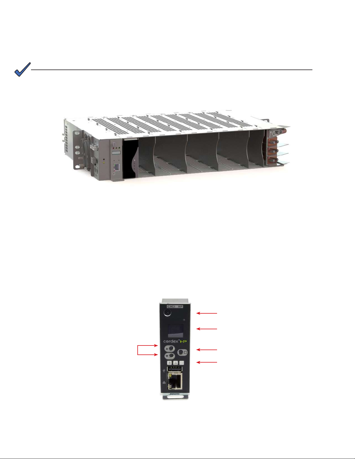
Figure 3 — LPS36 shelf (19" shown)
NOTE:
Figure 4 — CXCI HP controller front panel
4� 2 �1 Controllers
Both the CXCI HP and the CXCI+ controllers (Figure 4 and Figure 5) can be used in the shelves. For details on
using either controller go to the Alpha website to download the relevant software manual.
CXCI HP
CXCI HP in-shelf controllers have a small organic LED (OLED) display. This displays 30 characters total (six char-
acters wide, five lines high) and the controller has three navigation buttons and one reset button. The display has
three main operating modes: dashboard, menu and screen saver.
After 20 minutes with no activity, the controller goes into screen saver mode and the display shuts off. From
screen saver mode, press any of the three navigation buttons to re-activate the screen and enter dashboard
mode.
Forward and Back Buttons
to Scroll through menus
LED Status Indicators
•Green - Ok
• Yellow - Minor alarm
• Red - Major alarm
LED Display
Select Button to Enter Menus
and Execute Commands
Reset Button
Blanks must be installed when using fan trays to allow proper air flow to the
modules, see sections 6.4.2.
4.2 LPS36 System Features (19"/23")

17
0120011-J0 Rev M
LEDs
Each controller has three LEDs located on the front panel. These are used to display the alarm status of the power
system, controller progress and status during startup, as well as file transfers.
Alarm Conditions
The controller illuminates the LED that corresponds to the system alarm status. Only one LED is illuminated at a time
during alarm conditions. The following show the corresponding alarm status for each LED color:
Green:OK, no alarms
Yellow:Minor alarm, no major alarms
Red:Major alarm
Progress and Status Indication
The LEDs are also used in the following situations:
• Base unit validation – all three LEDs are on at the same time.
• File transfer – when recovering from invalid firmware application – the red LED is illuminated.
Reset
Refer to Section "Controller Reset" on page 53 for reset options.
Figure 5 — Cordex CXCI+ controller front panel
Ethernet port
Soft reset: push once
Reset IP address: hold
for 3 seconds
LCD screen (displays
Voltage or Current)
Display pushbutton toggle
switch for Voltage or Current
Hard reset: push once
System status LEDs
Locking screw
CXCI+ Controller
The controller brings advanced monitoring technology to the Cordex series of converters. A single controller man-
ages up to 9 converter modules. This compact system controller is equipped with the complete range of Cordex
software features, including the following:
• Ethernet port for local and remote communications
• User definable alarms
• Daily logging of power system events and system statistics

0120011-J0 Rev M
18
Figure 6 — Shelf Connections
4�2�2 Shelf Connections and Indicators (19" and 23" only)
Connections to the load and local alarm-sending unit are conveniently located on the side of each shelf.
Fan power connector
Major alarm relay
Minor alarm relay
50-pin load
connectors
CAN connectors
Shelf ID rotary switch
J1 J2
4�2�3 Alarm Relays (Form C Contacts)
The converter shelf has an interface panel with terminal blocks for Major and Minor alarm outputs (Form C contacts),
which are controlled by the controller. The Major alarm relay is designed to “fail safe” to ensure the alarm is regis-
tered when power is removed
Figure 7 — Shelf Alarm LEDs
OFF: Ok, no alarms
Red: Major alarm
Yellow: Minor alarm
Major Alarm
The Major alarm relay de-energizes under any one of the following conditions:
• When two or more outputs have failed within a shelf
• When the DC input feed is below the normal operating voltage
• When the DC input feed is above the normal operating voltage
Minor Alarm
The Minor alarm relay is de-energized under any one of the following conditions:
• Single output has failed within a shelf
• Internal ambient temperature is out of range
Alarm LEDs
On the front of the interface panel, are two LEDs—one red and one yellow, which indicate the shelf alarm status
(Figure 7).
If a Major alarm is activated, it "resets" the Minor
alarm relay to an energized state.
NOTE:
Table of contents
Other EnerSys Power Supply manuals

EnerSys
EnerSys alpha APX3 Series User manual

EnerSys
EnerSys alpha Cordex CXRF 48-3.6kW Quick start guide

EnerSys
EnerSys alpha APX3-G Series User manual

EnerSys
EnerSys Alpha Broadband UPS User manual

EnerSys
EnerSys Alpha XRT-TPPL User manual

EnerSys
EnerSys Alpha FMPS FTTP User manual

EnerSys
EnerSys alpha CXPS-E3 User manual


