http://www.ia.omron.com/ 2
(c)Copyright OMRON Corporation 2007 All Rights Reserved.
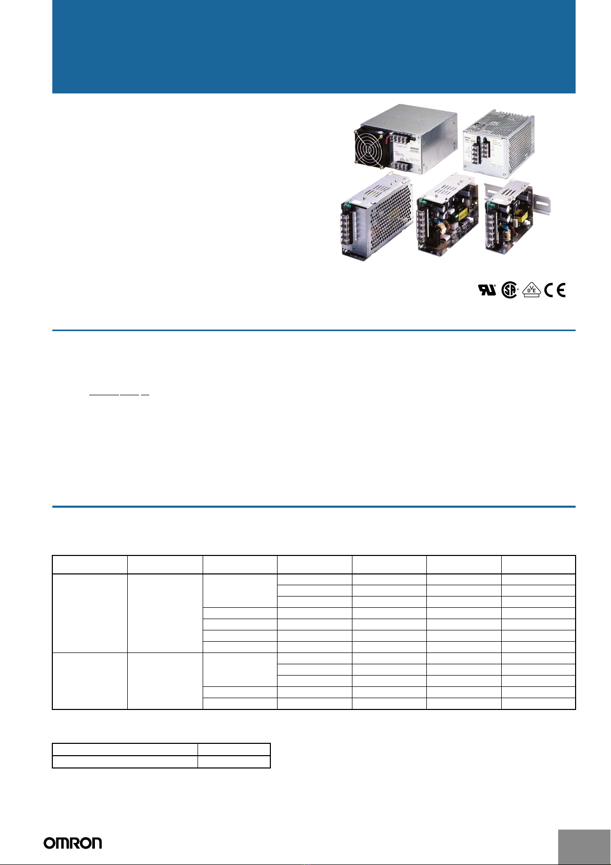
S8PS
Specifications
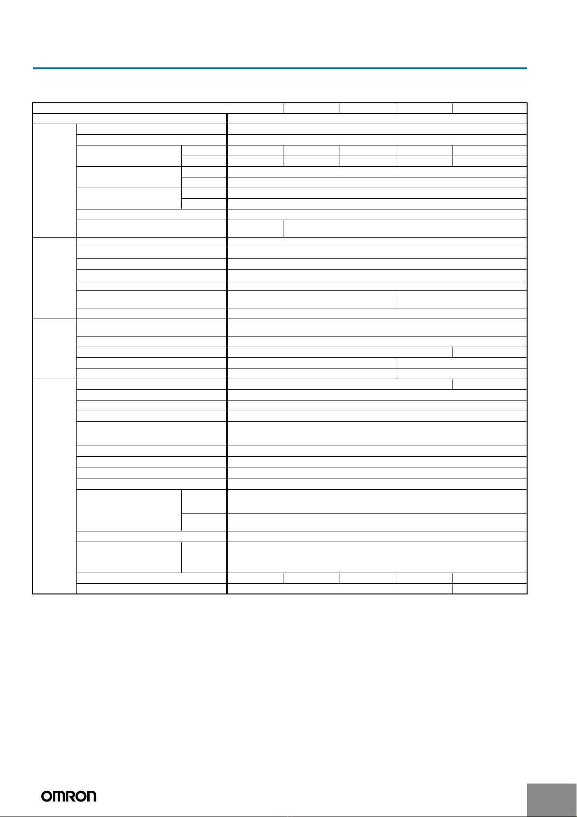
■Ratings/Characteristics
Note: 1. Do not use an inverter output for the Power Supply. Inverters with an output frequency of 50/60 Hz are available, but the rise in the internal
temperature of the Power Supply may result in ignition or burning.
2. A 100% load for rated input voltage (100 VAC or 200 VAC).
3. If the output voltage adjuster (V. ADJ) is turned, the voltage will increase by more than 10% of the voltage adjustment range. When ad-
justing the output voltage, confirm the actual output voltage from the Power Supply and be sure that the load is not damaged.
4. The output will shut off and the protection-ON alarm indicator will simultaneously light. Turn OFF the input power supply, wait 1 min., and
then turn ON the input power supply to recover normal operation.
5. Turn OFF the input power supply, wait 1 min., and then turn ON the input power to recover normal operation. (For 300-W and 600-W
models, the output will shut off and the protection-ON indicator will simultaneously light.)
6. The weight indicated is for a front-mounting open-frame model. (includes the cover for 300-W and 600-W front-mounting models.)
Item 50 W 100 W 150 W 300 W 600 W
Efficiency (typical) 74% to 80% (depends on the model)
Input Voltage (See note 1.) 100 to 240 VAC (85 to 264 VAC)
Frequency (See note 1.) 50/60 Hz (47 to 63 Hz)
Current (See note 2.) 100-V input 0.9 A max. 1.8 A max. 2.7 A max. 5.4 A max. 10 A max.
200-V input 0.45 A max. 0.9 A max. 1.4 A max. 2.7 A max. 5 A max.
Leakage current (See note 2.) 100-V input 0.5 mA max.
200-V input 1.0 mA max.
Inrush current (See note 2.) 100-V input 25 A max. (for a cold start at 25°C)
200-V input 50 A max. (for a cold start at 25°C)
Power factor (See note 2.) 0.95 typical
Harmonic current standards Based on EN
61000-3-2
Complies with EN 61000-3-2
Output Voltage adjustment range (See note 3.) −5% to 10%
Ripple (See note 2.) 2% (p-p) max.
Input variation influence 0.4% max. (at 85 to 132 VAC input/at 170 to 264 VAC input, 100% load)
Load variation influence 0.8% max. (with rated input, 0 to 100% load)
Temperature variation influence (See note 2.) 0.05%/°C max.
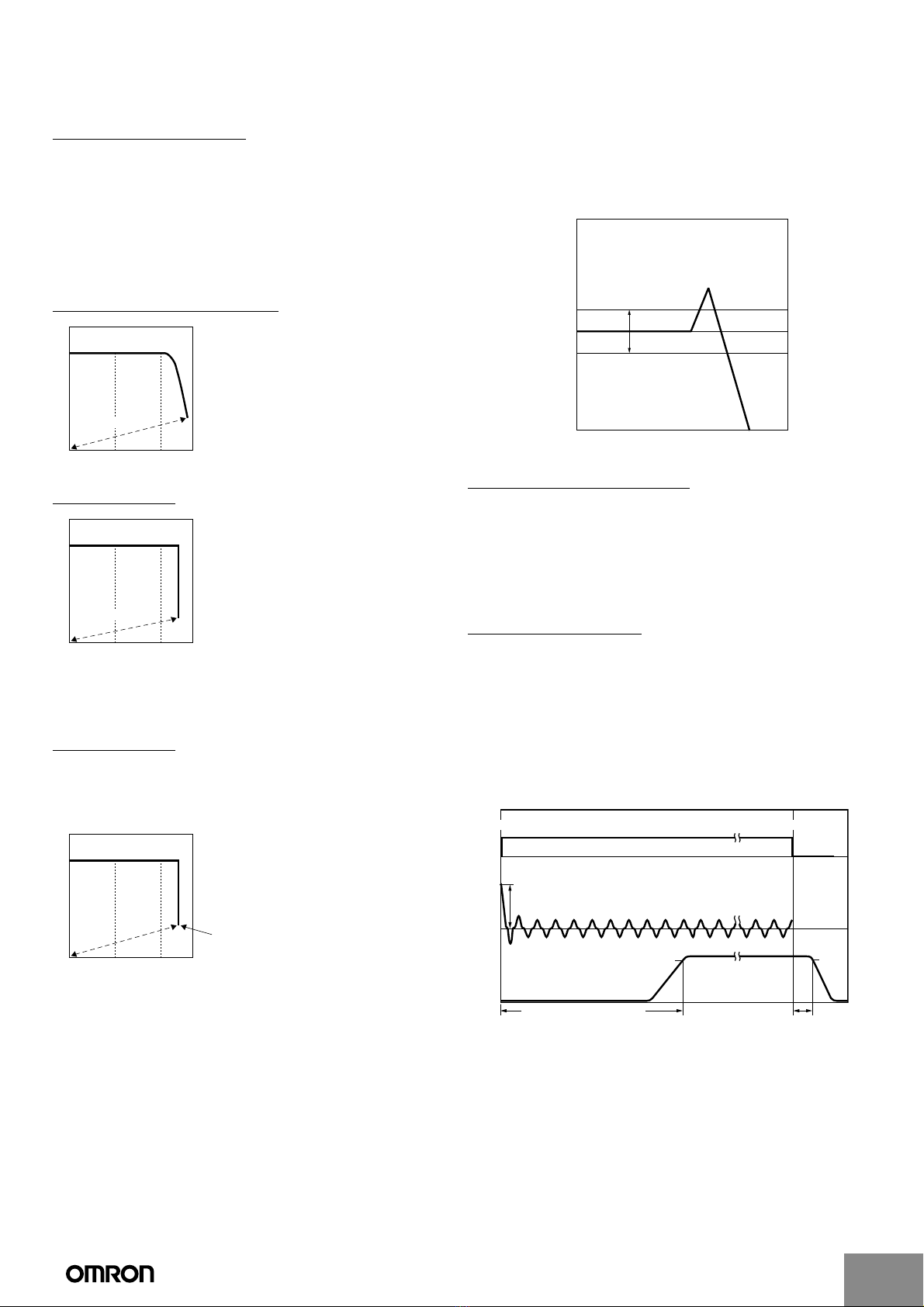
Startup time 1,000 ms max. (up to 90% of output voltage at rated out-
put voltage/current)
1,500 ms max.
Hold time (See note 2.) 20 ms min.
Additional
function
Overload protection 105% min., voltage drop, intermittent operation
(With the 600-W model, output is turned OFF at 5 s min.)
Overvoltage protection (See note 5.) Ye s
Overheat protection No Ye s
Protection-ON alarm indicator No Yes (color: red)
Parallel operation No Yes, 2 units max.
Other Heat radiation Natural air-cooling Built-in fan
Ambient operating temperature Refer to the derating curve in Engineering Data (with no icing or condensation).
Storage temperature −25 to 65°C
Ambient operating humidity 25% to 85%
Dielectric strength 3.0 kVAC for 1 min. (between all inputs and outputs)
2.2 kVAC for 1 min. (between all inputs and PE terminal)
1.0 kVAC for 1 min. (between all outputs and PE terminal)
Insulation resistance 100 MΩmin. (between all outputs and inputs/PE terminal at 500 VDC)
Vibration resistance 10 to 55 Hz, 0.75-mm amplitude for 2 h each in X, Y, and Z directions
Shock resistance 300 m/s2, 3 times each in ±X, ±Y, and ±Z directions
Output indicator Yes (color: green)
EMI Conducted
Emission
(See note 2.)
Conforms to EN61204-3 EN55011 Class B and based on FCC Class B
Radiated
Emission
Conforms to EN61204-3 EN55011 Class B
EMS Conforms to EN61204-3 High severity levels
Approved standards UL
cUL
cUR
EN/VDE
UL508, UL1012, UL60950-1
CSA C22.2 No. 14
CSA No. 60950-1
EN50178 (=VDE0160), EN60950-1 (=VDE0805 Teil 1)
Weight (See note 6.) 420 g max. 600 g max. 735 g max. 2,200 g max. 3,500 g max.
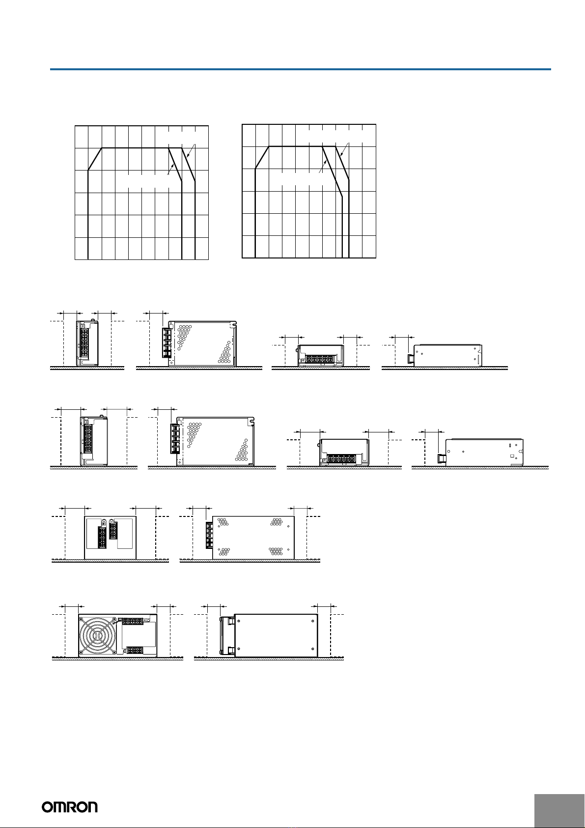
Mounting method Front Mounting Bracket or DIN Rail Mounting Bracket Front Mounting Bracket