SMARTfit Mini Low Impact Portable User manual

SMARTfit Mini Low Impact Portable Assembly
Manual
Version 1.4
www.smartfitinc.com

1Customer Service: 1-805-451-2488 x 112 www.smartfitinc.com
Table of Contents
IMPORTANT SAFETY INSTRUCTIONS ....................................................................................................... 2
Maintenance.......................................................................................................................................... 3
Getting Started....................................................................................................................................... 4
Unpackage the SMARTfit Mini Low Impact Portable ............................................................................... 5
Install the SMARTfit Mini Low Impact Portable ....................................................................................... 8
EU Declaration of Conformity (DoC) ..................................................................................................... 22

2Customer Service: 1-805-451-2488 x 112 www.smartfitinc.com
IMPORTANT SAFETY INSTRUCTIONS
(READ ALL INSTRUCTIONS)
CAUTIONS, WARNINGS and DANGERS
•This is not a toy and is intended for use by or under the supervision of adults.
•To reduce the risk of fire, replace only with a fuse of the same type and electrical rating.
•There are No user serviceable parts with the exception of the fuse.
•Please note the yellow CAUTION and WARNING labels on the device.
•Note all pinch points on the device before using.
•If an extension cord is used, pay close attention to the current requirement and routing to
eliminate tripping hazards.
•Pay close attention to the pinch points pointed out in yellow CAUTION labels.
•Do not climb on the device.
•This appliance is not intended for use by persons (including children) with reduced physical,
sensory or mental capabilities, or lack of experience and knowledge, unless they have been
given supervision or instruction concerning use of the appliance by a person responsible for
their safety.
•Children should be supervised to ensure that they do not play with the appliance.
•PLEASE SAVE THESE INSTRUCTIONS

3Customer Service: 1-805-451-2488 x 112 www.smartfitinc.com
Maintenance
•Clean all surfaces with a water-based disinfectant, such as Windex Disinfectant.
•Check all bolts and ensure they are tightened.
•Check all mechanical parts for wear.
•Check wiring for wear and fraying.

4Customer Service: 1-805-451-2488 x 112 www.smartfitinc.com
Getting Started
The SMARTfit Mini System Includes the Following:
•Software License including downloadable iOS/Android mobile application and data
gathering/reporting module.
•CPU controller, timeclock, score display, sound system with 4 tracks of voice /tones/music.
•LED targets: multicolored high resolution, super bright, 16 x 16 dot matrix. Allows for images,
symbols, numbers up to 999 and three letter words.
•37 categories consisting of hundreds of options that can be scaled to the ability level of players
regardless of capability.
•Adjustable touch sensitivity to suit the light touch of a hand or the weight of a medicine ball.
•18-month warranty and SMARTfit’s exclusive Platinum Service Plan. Extended warranty
available.
Customer Service
If you need assistance, feel free to give our Customer Service a call at 1-805-256-0278, between the
hours of 8:00 a.m. and 4:30 p.m. PST, Monday through Friday.
5Customer Service: 1-805-451-2488 x 112 www.smartfitinc.com
Unpackage the SMARTfit Mini Low Impact Portable
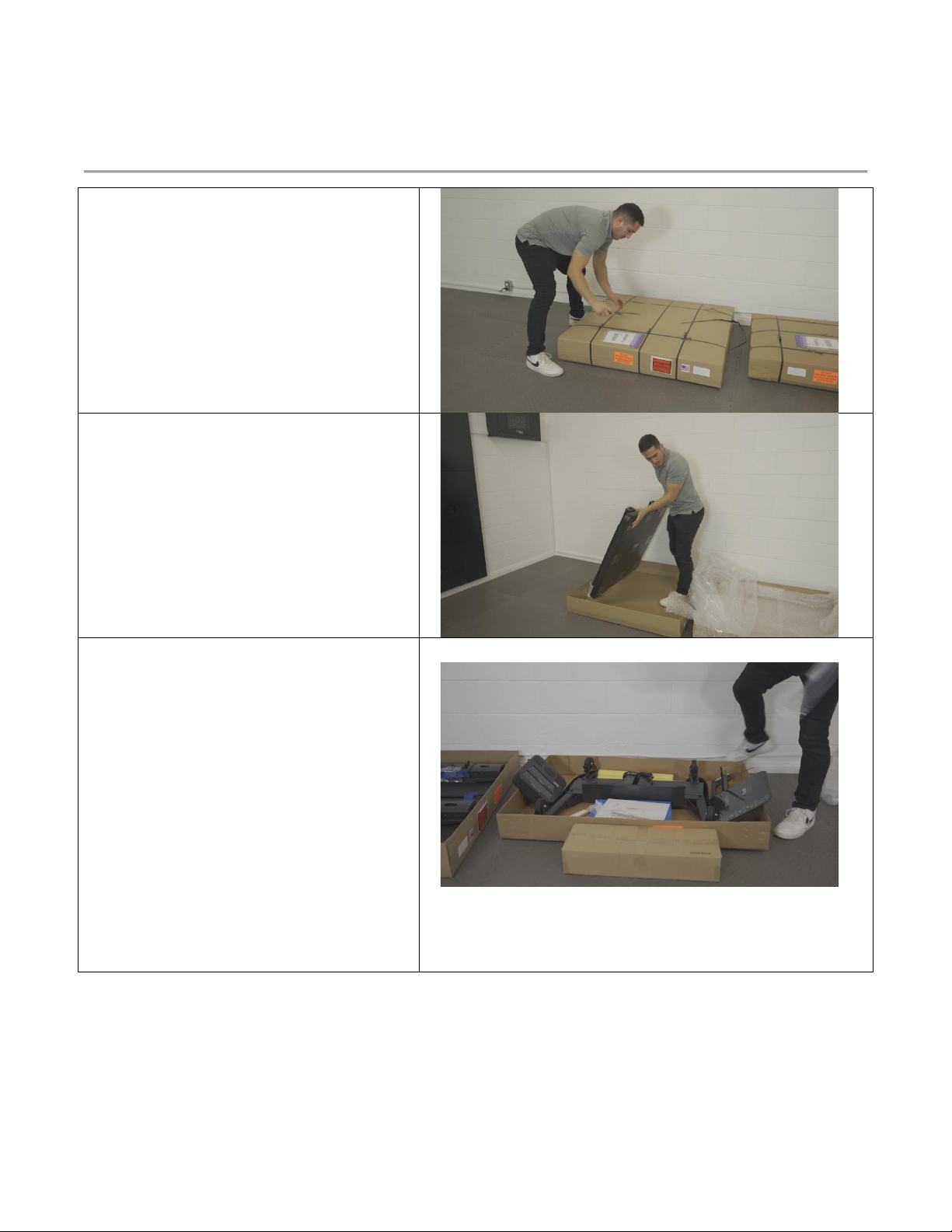
1. Layout all received packages near
an open area. Inspect all boxes
before opening them. Photograph
any damage.
2. Now unpack the first box.
3. This box contains the Low Impact
Mini Panel. Lay it down safely in the
packaging material so that it cannot
damage the floor.
4. Now unpack the final box.
5. This box will include the wheelbase,
the Controller, the Controller
Backplate with an Attachment Arm,
two Pool Noodles, one Air Rex Pad,
a pair of drumsticks, a QR/NFC
wristband, and the portable tablet
stand.
6. Each Item will be identified below.
Compare the listed items below to
the boxed items you have received
in order to make sure all items have
been sent.

6Customer Service: 1-805-451-2488 x 112 www.smartfitinc.com
7. This is the wheelbase that will
attach to the panel.
8. This is the SMARTfit Controller.
9. This is the Controller Backplate
with an Attachment Arm.
10. The attachment arm will connect
to the side of the panel and the
Controller will attach to the backplate.
11. The system power supply and
power cable are secured onto the back
of the backplate. Additional cable in
black tubing will run loosely through
zip ties down the back of the panel.
Be careful not to overtighten them.

7Customer Service: 1-805-451-2488 x 112 www.smartfitinc.com
12. Yellow and blue pool noodles are
used for striking the targets.
13. Hurdles are included to enhance
motor coordination during SMARTfit
training sessions.
14. Drumsticks are included to help
frail clients strike each target.
15. Sample QR/NFC wristbands for
easy log in by clients. Client can scan
wrist band after initial client account
has been created.
16. The Portable Tablet stand and
assembly instructions are included
inside this package.
17. In order to assemble your system
in the next section of this manual, you
will need to have the following tools at
your disposal.
18. A Utility Knife, a 10 millimeter
socket and ratchet, a Phillips #2
Screwdriver, a Hex 3 millimeter
screwdriver, and cutters for the zip
ties.
8Customer Service: 1-805-451-2488 x 112 www.smartfitinc.com
Install the SMARTfit Mini Low Impact Portable
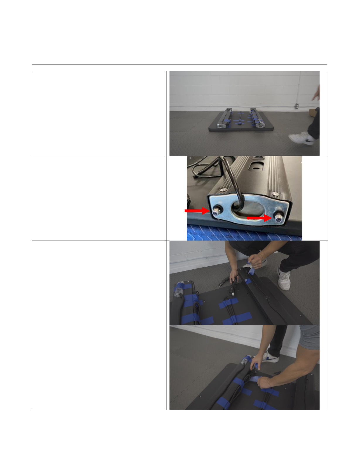
1. Turn over the panel so that the
targets are facing down toward the
floor or a table.
2. The panel weighs 70 lbs, so two
people are required to handle it.
3. Now you are ready to attach the
wheelbase to the panel.
4. Use a 10-milimeter socket and ratchet to
remove the nut and the washer near the
bottom of the panel.
5. There will be 2 nuts and 2 washers at the
bottom of each post. A total of 4 nuts
and 4 washers.
6. Once removed, undo the tape holing
down the wire bunch near the
screws we removed the nuts and
washers from.
9Customer Service: 1-805-451-2488 x 112 www.smartfitinc.com
7. For this next step we made sure to
set the panel face down on a table so
that it was easier for us to attach the
wheelbase.
8. First, unravel the wires at the end of
each post so that they can be fed
through the wheelbase in the next
step.
9. One of the posts, will have two wires.
The shorter wire of the two should
not be fit through the wheelbase.
10. Place the wheelbase near the screws
at the end of the posts. Thread the
single wire through the designated
holes within the wheelbase.
10 Customer Service: 1-805-451-2488 x 112 www.smartfitinc.com
11. Secure the wheelbase onto the panel
using the 4 screws we removed the
nuts and washers from earlier.
12. Reattach the washer and nut to each
screw and secure it using the 10-
millimeter socket and ratchet.
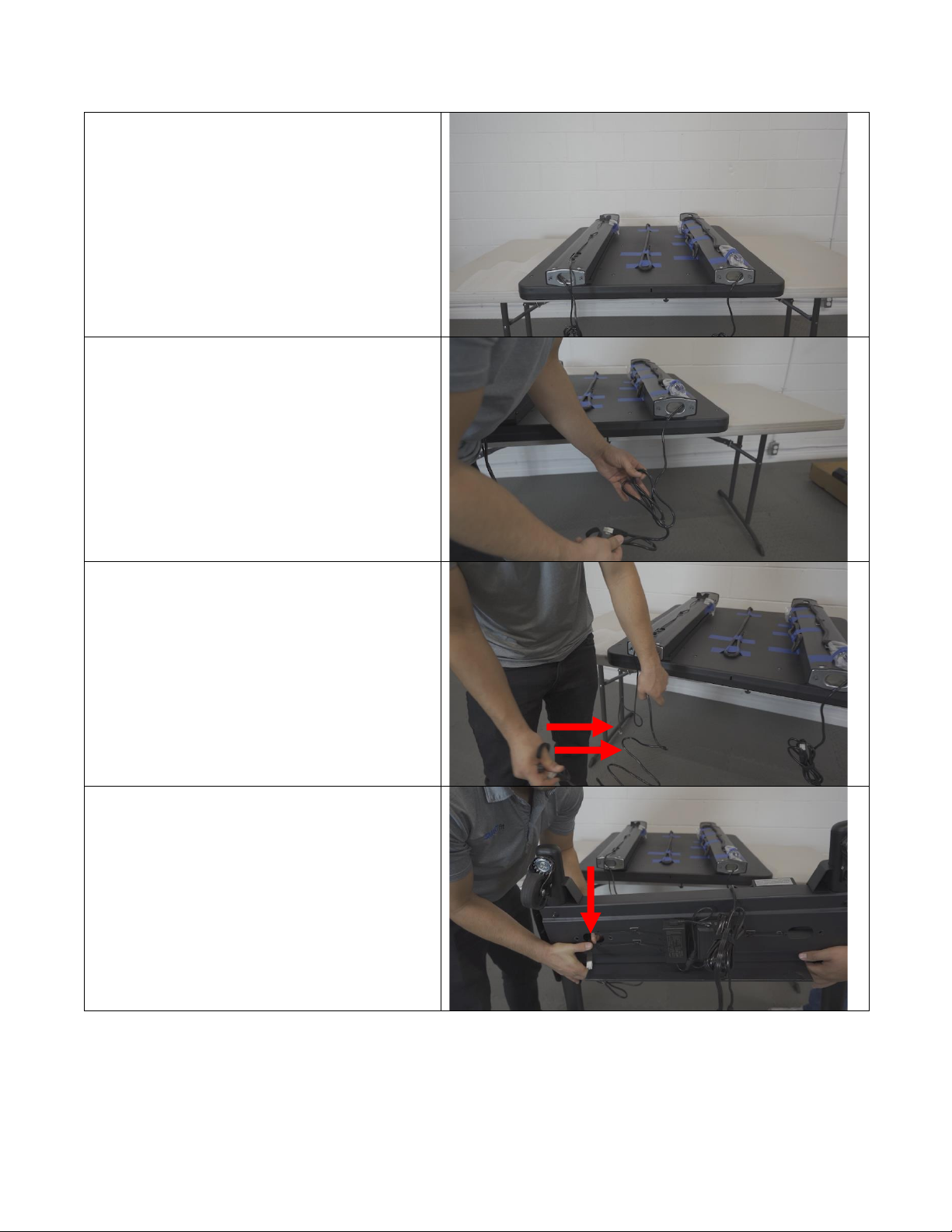
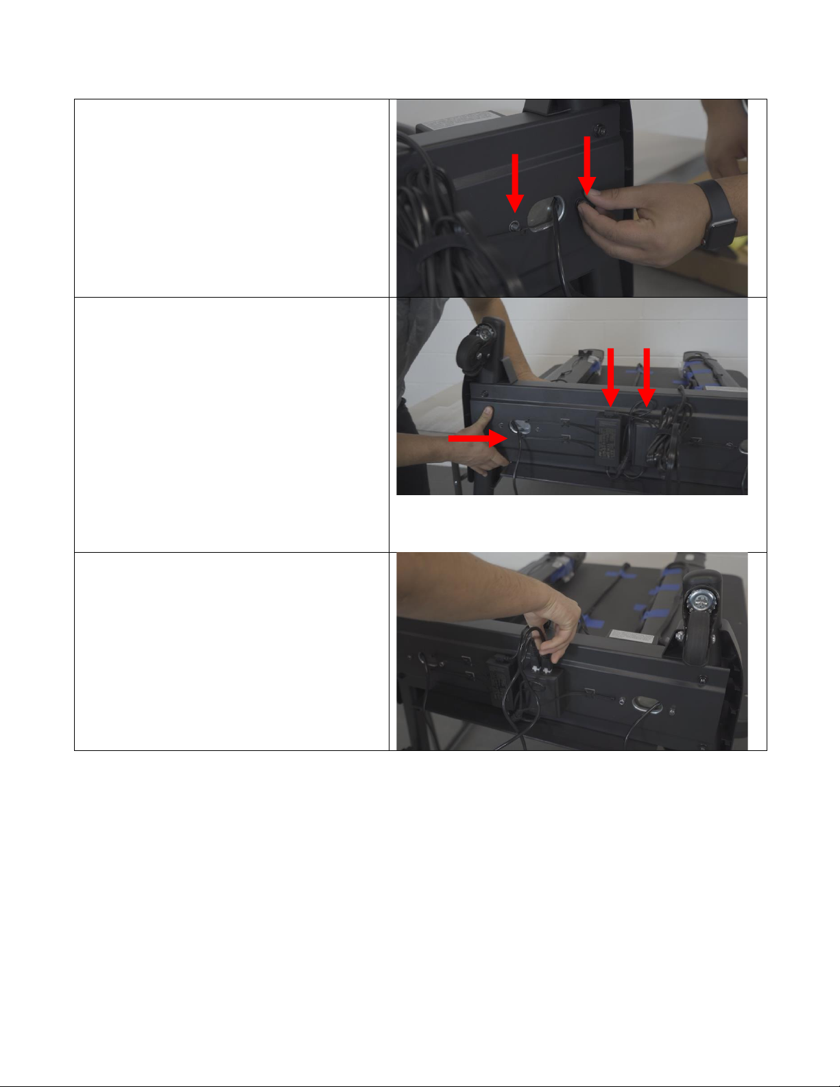
13. There are two power supplies on the
bottom of the wheelbase. The power
supply for the actuators is on the
right and the power supply for the
keypad is to the left.
14. The threaded single wire coming
from the bottom of each panel and
through the wheelbase will connect
to the white connector ports on the
power supply controlling the
actuators.
15. The left wire will plug into the left
side of the power supply and the
right wire will plug into the right side.

11 Customer Service: 1-805-451-2488 x 112 www.smartfitinc.com
16. The final wire connected to the
keypad can be brought over the back
edge of the wheelbase.
17. This is the same wire that we did not
thread through the wheelbase. Plug
this wire into the bottom of the
power supply controlling the
actuators.
18. Wrap the final cable as neatly as
possible using the provided zip ties.
19. Remove the system from the table
and stand it on its feet.
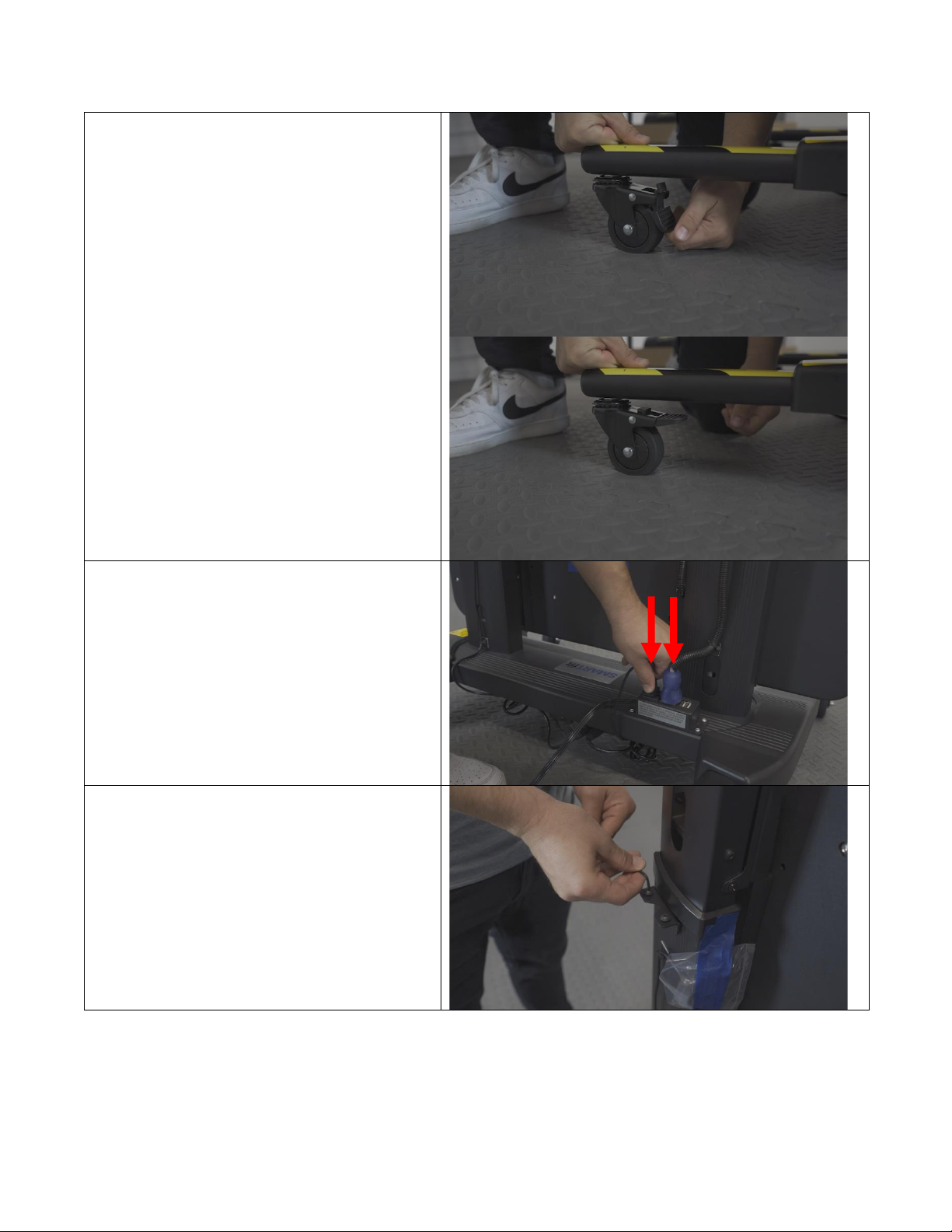
12 Customer Service: 1-805-451-2488 x 112 www.smartfitinc.com
20. To move the system around, unlock
all 4 wheels by disabling the breaks.
You can re-enable them at any time.
21. There are a total of two wires that
need to be plugged into the power
outlet attached to the back end of
the wheelbase.
22. Next, we will attach the keypad
controlling the movement of the
panel.
23. Remove the two screws located on
the back end of the right post.
13 Customer Service: 1-805-451-2488 x 112 www.smartfitinc.com
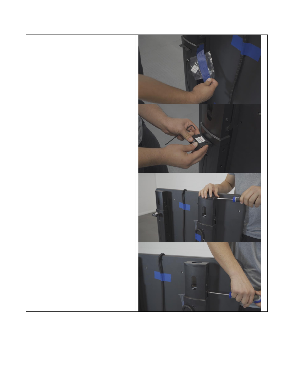
24. The keypad will be taped nearby and
wrapped in plastic.
25. Align the screw holes on the bracket
and keypad.
26. Secure the screws using a hex 3-
millimeter screwdriver.
27. Next, we will attach the Controller
backplate.
28. First, remove the two screws from
the top of the left post. A Phillips #2
screwdriver will do the trick.
14 Customer Service: 1-805-451-2488 x 112 www.smartfitinc.com
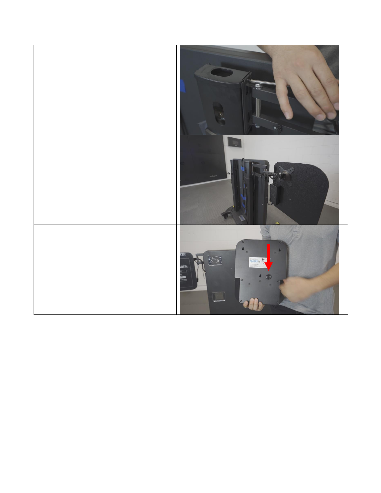
29. Align the backplate with these screw
holes and secure the backplate.
30. See the photo to ensure that the
Controller backplate is facing the
correct direction.
31. The Controller will be attached next.
32. First, remove the knob at the back of
the Controller.

15 Customer Service: 1-805-451-2488 x 112 www.smartfitinc.com
33. Align and attach the 3 hooks on the
backplate to the 3 holes on the back
of the Controller.
34. Reattach the knob to secure the
Controller onto the backplate.
35. There are two wires that need to
plug into the Controller to give the
system power.
36. This wire will power the targets.
Remove the blue tape holding it
down.

16 Customer Service: 1-805-451-2488 x 112 www.smartfitinc.com
37. This wire will power the entire
system. Remove the blue tape
holding it down as well.
38. Plug the power cord into the power
supply attached to the back of the
Controller backplate.

17 Customer Service: 1-805-451-2488 x 112 www.smartfitinc.com
39. Notice the shape of the target wire
and plug it into the side of the
Controller.
40. Notice the shape of the power cord
wire and plug it the controller, just
above the target wire.
41. There are 3 provided zip tie
locations.
42. Thread the power cables through
each attached zip tie while making
sure there is room for the cables to
move fluidly through them when the
panel goes up and down. Leave a 1-
inch diameter hole in each zip tie.
18 Customer Service: 1-805-451-2488 x 112 www.smartfitinc.com
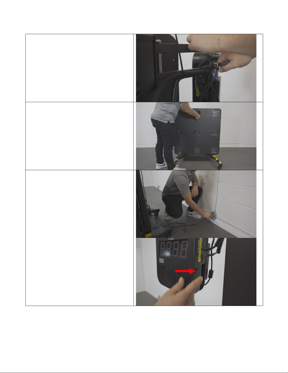
43. Tighten the zip ties in all 3 locations.
Cut the end of each zip tie to make it
look nice.
44. Remove the plastic on all 9 targets.
45. Plug the power cord into a wall
outlet to give the system power.
46. Turn the power switch on located on
the side of the Controller.

19 Customer Service: 1-805-451-2488 x 112 www.smartfitinc.com
47. Each target should light up along
with the Controller.
48. At this point, the keypad can be used
to adjust the position of the panel in
relation to the participant using
SMARTfit.
Table of contents
Popular Laboratory Equipment manuals by other brands


Micromeritics
Micromeritics MicroStar 022 installation guide

Grant-bio
Grant-bio PTR-35 operating instructions

BIO RAD
BIO RAD Bio-Scale instruction manual

Funke Gerber
Funke Gerber CryoStar I manual

Peak Scientific
Peak Scientific Solaris 10 user manual

Halma
Halma Ocean Optics DH-mini Installation and operation manual