Halma Ocean Optics DH-mini User manual

DH-mini UV-Vis-NIR Deuterium-Halogen
Light Source with Shutter
Installation and Operation Manual
Document Number 000-10000-200-02-201506b
For Products: DH-mini UV-Vis-NIR
Document: 000-10000-200-02-201506b

AMERICAS & WORLD HEADQUARTERS
Phone: +1 727-733-2447
Fax: +1 727-733-3962
EUROPE, MIDDLE EAST & AFRICA
Phone: +31 26-319-0500
Fax: +31 26-319-0505
Email: [email protected]
Germany : +49 711-341696-0
UK : +44 1865-811118
France : +33 442-386-588
ASIA
Phone: +86 21-6295-6600
Fax: +86 21-6295-6708
Email: [email protected]
Japan & Korea: +82 10-8514-3797
www.oceanoptics.com
Copyright © 2014 Ocean Optics, Inc.
All rights reserved.
Trademarks
All trademarks within are the property of their respective owners.
Limit of Liability
Every effort has been made to make this manual as complete and as accurate as possible, but no warranty or fitness is implied. The information provided is on an
“as is” basis. Ocean Optics, Inc. shall have neither liability nor responsibility to any person or entity with respect to any loss or damages arising from the
information contained in this manual.
Ocean Optics, Inc.
830 Douglas Ave.
Dunedin, FL 34698
USA
Manufacturing & Logistics
4301 Metric Dr.
Winter Park, FL 32792
USA
Ocean Optics Asia
666 Gubei Road
Kirin Tower Suite 601B
Changning District
Shanghai
PRC, 200336
Sales & Support
Geograaf 24
6921 EW Duiven
The Netherlands
Manufacturing & Logistics
Maybachstrasse 11
73760 Ostfildern
Germany

000-10000-200-02-201506b A
Important Safety Notices
1. Do not remove or modify any installed safety device on this equipment. Doing so will void your
warranty and create an unsafe operating environment.
2. Dangerous voltages are present in this device. There are NO user serviceable parts inside.
3. Only allow qualified personnel to service this unit.
4. Handle this product with care. Do not use the unit if it is damaged in any way. Contact your
dealer for repair or replacement information.
5. Do not stare into the light beam.
6. UV radiation is present. Direct contact with the light beam will cause injury.

Important Safety Notices
B 000-10000-200-02-201506b

000-10000-200-02-201506b i
Table of Contents
About This Manual .............................................................................................................iii
Document Purpose and Intended Audience..............................................................................iii
Document Summary..................................................................................................................iii
Product-Related Documentation ...............................................................................................iii
Upgrades............................................................................................................................iii
Warranty.............................................................................................................................iv
Chapter 1: Setup...................................................................................1
Overview.............................................................................................................................1
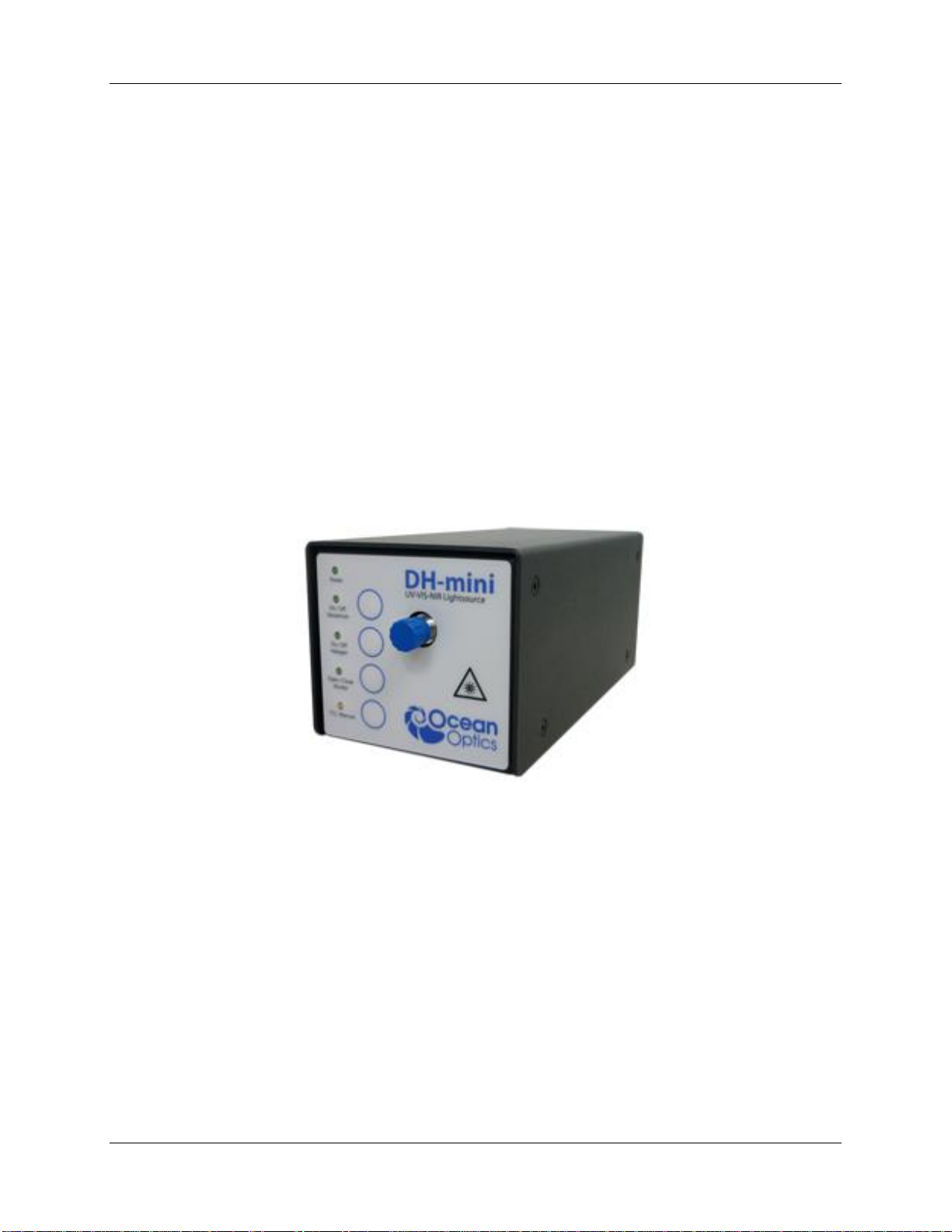
Unpacking the DH-mini ......................................................................................................1
Contents .............................................................................................................................2
Attaching to Ocean Optics Spectrometers ........................................................................2
Setting Up the DH-mini Light Source.................................................................................2
Chapter 2: Operation ...........................................................................5
Overview.............................................................................................................................5
Operating Modes................................................................................................................5
Manual Mode.............................................................................................................................6
TTL Mode ..................................................................................................................................6
Change Intensity of Halogen Bulb .....................................................................................8
Appendix A: Specifications.................................................................9
Specifications .....................................................................................................................9
Spectral Output ..................................................................................................................10
Parts List.............................................................................................................................10
Appendix B: Bulb Replacement .........................................................11
Overview.............................................................................................................................11
Replacing the Bulb.............................................................................................................11

000-10000-200-02-201506b iii
About This Manual
Document Purpose and Intended Audience
This document provides you with information to get your light source set up and running, as well as how
to operate the device and change the bulb. Specifications are also included.
What’s New in this Document
This version of the DH-mini Light Source Installation and Operation Manual updates the TTL connector
pinouts.
Document Summary
Chapter
Description
Chapter 1: Setup
Contains instructions for setting up the unit.
Chapter 2: Operation
Provides instructions for operating the unit, including
using Manual and TTL modes, as well as changing
the intensity of the Halogen bulb.
Appendix A: Specifications
Contains operating environment specifications, as
well as other physical details of the product.
Appendix B: Bulb Replacement
Provides instructions for changing the bulb.
Product-Related Documentation
You can access documentation for Ocean Optics products by visiting our website at
http://www.oceanoptics.com. Select Support → Technical Documents, then choose the appropriate
document from the available drop-down lists. .
Upgrades
Occasionally, you may find that you need Ocean Optics to make a change or an upgrade to your system.
To facilitate these changes, you must first contact Customer Support and obtain a Return Merchandise
Authorization (RMA) number. Please contact Ocean Optics for specific instructions when returning a
product.

About This Manual
iv 000-10000-200-02-201506b
Warranty
Ocean Optics GmbH warrants to the original user of this instrument that it shall be free of any defects
resulting from faulty manufacture of this instrument for a period of 12 months from the original data of
shipment.
This instrument should not be used for any Clinical or Diagnostic purposes. Data generated in these
areas is not warranted in any way by Ocean Optics GmbH. Any defects covered by this Warranty shall be
corrected either by repair or by replacement, as determined by Ocean Optics GmbH.
There are no warranties that extend beyond the description herein.
This Warranty is in lieu of, and excludes, any and all other warranties or representations expressed,
implied, or statutory, including merchantability and fitness, as well as any and all other obligations or
liabilities of Ocean Optics GmbH including, but not limited to, special or consequential damages. No
person, firm, or corporation is authorized to assume for Ocean Optics GmbH. Any additional obligation
or liability not expressed provided for herein except in writing duly executed by an officer of Ocean
Optics GmbH:
Ocean Optics GmbH
Maybachstraße 11
D-73760 Ostfildern
Tel.: +49 (0)711 34 16 96-51 • Fax.: +49 (0)711 34 16 96-85
e-mail: Info@oceanoptics.eu

000-10000-200-02-201506b 1
Chapter 1
Setup
Overview
The following sections provide instructions on unpacking and setting up your DH-mini Light Source.
Before using the DH-mini for the first time, check for transport damage. Be sure to adhere to all warnings
on the unit and in this manual.
Unpacking the DH-mini
►Procedure
1. Unpack your lamp assembly carefully. Dropping this instrument can cause permanent damage.
2. Inspect the outside of the instrument and make sure that there is no damage. Do not use the
instrument if damage is present. Contact your dealer for repair or replacement information, if
necessary.
3. Use this instrument in a clean environment.

1: Setup
2000-10000-200-02-201506b
Contents
Your DH-mini package should contain the following:
DH-mini Light Source
Power supply –12 Vdc @ max. 1500 mA
Hexagonal socket screw key SW 2.0
Hexagonal socket screw key SW 1.5
TTL adapter cable 4-way Binder plug to DB-15 connector
Attaching to Ocean Optics Spectrometers
The following table shows accessories and pinouts for attaching the DT-mini light source to various
Ocean Optics spectrometers.
DB15
Pin
DH Mini
HR/QE/Maya/NIRQuest
Flame
STS
USB2000+
Cables/Adapters Needed
N/A
HR4-CBL-DB15
FLAME-CBL-
DD4P-DB15P
JAZ-CBL-
DB15
USB-ADP-BB
(modified) + HR4-
BB-ADP
Pinouts
6
Halogen
GPIO 8
GPIO 1
RX (not
supported)
GPIO 6
10
GND
GND
GND
GND
GND
13
Shutter
Lamp Enable
Lamp Enable
Lamp Enable
Lamp Enable
15
Deuterium
GPIO 7
GPIO 4
GPIO4
GPIO 7
Setting Up the DH-mini Light Source
Use the following procedure to set up your light source.
►Procedure
Perform the steps below to set up your DH-mini Light Source:
1. Plug the power supply into a wall outlet.

1: Setup
000-10000-200-02-201506b 3
Power Supply
2. Plug the other end of the power supply cable into the socket on the rear panel of the DH-mini.
DH-mini Rear View
3. Connect the SMA connector of your fiber optic cable to the SMA plug on the front of the light
source.
Note
For UV measurements, a solar-resistant fiber is recommended.

1: Setup
4000-10000-200-02-201506b

000-10000-200-02-201506b 5
Chapter 2
Operation
Overview
The DH-mini Light Source includes both a deuterium and a halogen bulb for UV-VIS-NIR
measurements. There are two ways to control the DH-mini: using the push buttons on the front panel or
the TTL inputs on the rear panel. After power-on the Power LED will glow and the device will be in TTL
control mode which is highlighted by the yellow TTL/ Manual LED.
Operating Modes
To toggle between Manual Mode and TTL Mode you have to push the TTL/Manual button on the front
panel. The corresponding yellow LED next to the button toggles on and off with each push. A lit LED
indicates TTL Mode. If the LED is off, the device is in Manual Mode.
Manual mode –operates with the pushbuttons on the front panel
TTL mode –operates with the TTL inputs on the rear panel.

2: Operation
6000-10000-200-02-201506b
Manual Mode
In this mode you can switch the bulbs and the shutter via the corresponding push buttons.
Control
Action
Deuterium
Press button to turn Deuterium bulb on. The LED lights. Observe the warm-up time of 6
minutes to ensure that the light source has reached a stable operating state before taking
measurements.
Press button again to turn the Deuterium bulb off. The LED extinguishes.
Halogen
Press button to turn Halogen bulb on. The LED lights. Observe the warm-up time of 6
minutes to ensure that the light source has reached a stable operating state before taking
measurements.
Press button again to turn the Halogen bulb off. The LED extinguishes.
Shutter
Press button to open shutter. The LED lights.
Press button again to close the shutter. The LED extinguishes.
TTL/Manual
Press button to switch from Manual mode to TTL mode. The LED lights. See TTL Mode.
Press button again to switch from TTL mode to Manual mode. The LED extinguishes.
TTL Mode
The DH-mini always starts up in TTL mode. You can also switch to TTL mode by pressing the
TTL/Manual button (yellow LED is lit) if the light source is in Manual mode. The bulbs and the shutter
assume the state of the corresponding TTL signal when the light source is in TTL mode.
Note
If there are no signals connected to the logic ports o rear of the device, the device reads a
low signal (Deuterium bulb off, Halogen bulb off and shutter closed).

2: Operation
000-10000-200-02-201506b 7
The pinout of the TTL connector is as follows:
Pin #
Function
1
Deuterium control (5 V bulb on)
2
Halogen control (5 V bulb on)
3
Shutter control (5V shutter open)
4
GND
There is a TTL adapter cable available to directly attach the DH-mini on an Ocean Optics spectrometer
using a HR4-CBL-DB15 cable. The pinout on the male Sub-D-15 connector is as follows:
Pin #
Function
1
NC
2
NC
3
NC
4
NC
5
NC

2: Operation
8000-10000-200-02-201506b
Pin #
Function
6
Halogen control (5 V bulb on)
7
NC
8
NC
9
NC
10
GND
11
NC
12
NC
13
Shutter control (5 V shutter open)
14
NC
15
Deuterium control (5 V bulb on)
If you want to use OceanView to control the DH-mini via a spectrometer you can use the Strobe/Lamp
Enable check box to control the shutter. See Attaching to Ocean Optics Spectrometers for more pinout
information.
Change Intensity of Halogen Bulb
To change the intensity of the Halogen bulb, use trimmer screw on the left side of the device. Use a
flathead screwdriver to turn the screw clockwise to increase the intensity, counterclockwise to decrease it.
The full range can be set with approximately 30 screw rotations.

000-10000-200-02-201506b 9
Appendix A
Specifications
This section provides information on the operating environment, physical controls, and dimensions of the
DH-mini Light Source. It also provides a parts list.
Specifications
Specification
Value
Spectral range
200 –2500 nm
Light Output
Stability
Drift
<0.2% (standard deviation for k = 1)
<0.1% per hour (after 30 minutes stabilization)
Warm-up time
6 minutes at 20 °C
Power consumption
12 W
Optical fiber connection
SMA 905
Shutter input
TTL input, up to 2.5 Hz maximum
Pin position at SUB-D-15 pin adapter (all
pins are galvanically isolated)
Shutter: Pin 13
Deuterium bulb: Pin 15
Halogen bulb: Pin 6
GND: Pin 10
Lifetime average/guaranteed
2000 hours/ 1000 hours
Input line
12 Vdc @ 1 A max
Dimensions
75 mm x 82 mm x 175 mm (2.95 in. x 3.23 in. x 6.89 in.)
Weight
0.5 kg (1.1 pounds)
Ambient operating temperature
5 –35 °C
Relative humidity
Maximum 90%, noncondensing

A: DH-mini Specifications
10 000-10000-200-02-201506b
Spectral Output
The following graph shows spectral outputs of a DH-mini recorded with three spectrometers. All
spectrometers have measured irradiance spectra. The balance from the Deuterium spectrum (~200 –
400nm) to the Halogen spectrum (~400 –1600 nm) can be changed by varying the intensity of the
Halogen bulb (see Change Intensity of Halogen Bulb).
Parts List
Spare Parts / Order Information
Catalog Number
DH-mini UV-VIS-NIR Light Source
DH-mini
DH-mini Replacement bulb
DH-mini-B

000-10000-200-02-201506b 11
Appendix B
Bulb Replacement
Overview
If the lifetime of either the Deuterium bulb or the Halogen bulb is reached or if one bulb is broken you
can replace the bulbs. Both bulbs are arranged in one housing so the bulbs cannot be changed separately.
To order replacement bulbs for the DH-mini, see Spectral Output.
Replacing the Bulb
►Procedure
To replace the bulbs,
1. Remove all eight countersunk screws on each side of the light source housing with the provided
Hexagonal socket screw key SW 2.0.
2. Lift the housing off of the light source.

B: Bulb Replacement
12 000-10000-200-02-201506b
3. To remove the bulb, disconnect the cable at the rear side of the lamp first (1). Then use the
provided Hexagonal socket screw key SW 1.5 to loosen the stud screw (2).
4. Pull the bulb from the light source.
5. Insert a new bulb. Be careful to correctly align it with the connection holes on the PCB (3).
Table of contents
Other Halma Laboratory Equipment manuals