Smartflow FasTie User manual
Form #154 (08.17)
4500 E. 142nd Street • Grandview, MO 64030 • Tel. (816) 878-6675 • www.smartflow-usa.com
General
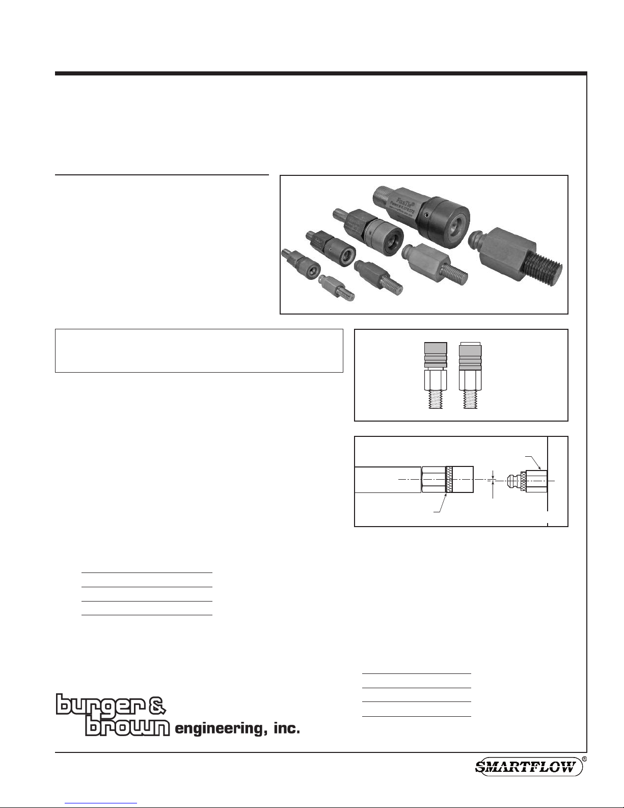
FasTie Quick-Connect Ejector System “ties-in” the
mold ejector plate to the press ejection system. A
pneumatically-operated piston inside the coupler
releases the pull stud from the press ejection system
to reduce set-up and change-out times.
Fixed-length FasTie Knockout Bars may be used
with the couplers and pull studs. The FasTie air
manifold option distributes shop air to each coupler.
The aluminum manifold supplies air to up to four
couplers. Pneumatic fittings and tubing are included.
Maintenance
Use Ultra High Temperature Synthetic Anti-Seize grease regularly on
the couplers for smooth operation. Visually inspect coupler each
month or each tool change for the presence of grease. Generously
apply grease to pull stud end, connect the coupler to the pull stud,
then release and repeat.
Before Installation
Before clamping a mold to the injection molding machine, the
machine ejector plate must be completely retracted to the “home”
position.
Align ent
Per figure 2, maximum center line misalignment per coupler
outside diameter is as follows.
1" HS ±3.5mm (±0.138")
1-3/8" ±5mm (±0.197")
2" ±6mm (±0.236")
3" ±5mm (±0.197")
Multiple Knockout Bar Lengths
When using two or more knockout bars in an installation, knockout
bars must be the same length within .05mm (.002") to assure even
coupler operation.
Smartflow®
FasTie® Quick-Connect Ejector Tie-In Syste
1"HS, 1-3/8", 2" & 3" Components, Installation Instructions
US Patent No. 6,379,072
figure 1
Coupler
Open
(sleeve fo wa d)
Coupler
Closed
(sleeve back)
Couplers shown in open position
FasTie Coupler
Maximum Center Line
Misalignment
HS
Pull Stud
HS
figure 2
Caution: Couplers must be in the open position before
connecting with pull studs. See figure 1. Coupler
damage will result from improper set-up.
Ejector Bar Length Note:
Individual ejector bars should not exceed 24" in
length to prevent sagging and excessive
coupler/pull stud misalignment.
It may be necessary to use two ejector bars for
extra-long ejector bar applications, one for each
pull stud and coupler.
Mini u Clearance Needed to
Disengage Coupler and Pull Stud
1" HS 15mm (0.59")
1-3/8" 21mm (0.81")
2" 25mm (1.00")
3" 34mm (1.34")
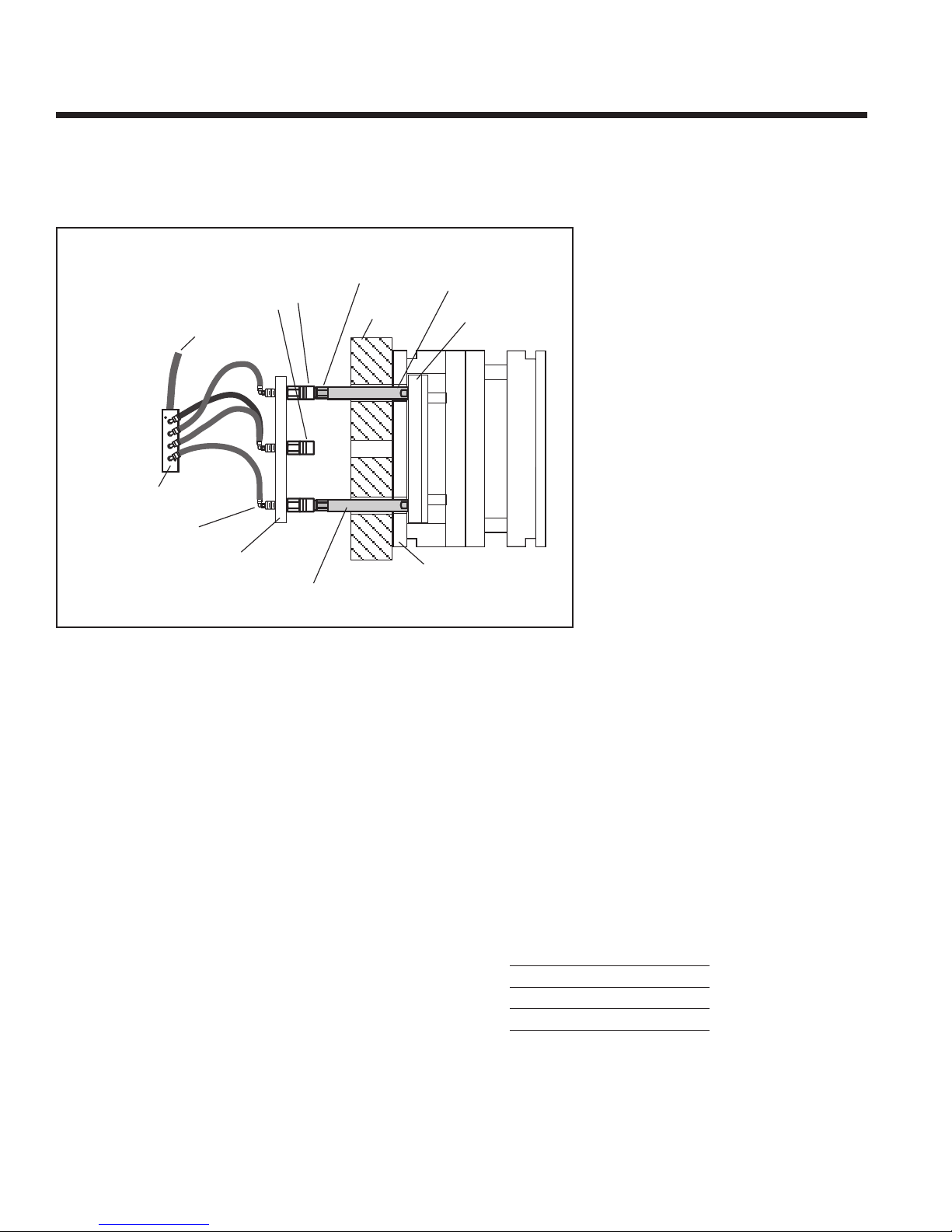
FasTie® Quick-Connect Ejecto Tie-In System
Couplers on Press Ejector Plate
fo multiple molds in the same machine with diffe ent ejecto
patte ns and diffe ent ejecto st okes
The following installation instructions are for reference only.
Installation may vary depending on the application and
customer preferences.
1. Install the coupler into the press ejector plate populating
for the required molding machine patterns (i.e. vertical,
horizonal and/or center knockout positions). Use thread-
locking compound to prevent movement during use.
2. Install pneumatic fitting to the coupler per figure 3.
3. If using the manifold accessory, mount the manifold and
tubing so they do not interfere with moving parts.
4. Connect shop air lines to the pneumatic fittings that feed
the FasTie couplers. Couplers must be in the open
position (see figure 1) before connection to pull studs,
otherwise coupler damage will occur.
5. Install the pull stud onto the end of the knockout bar.*
6. Insert the knockout bar assembly in the moving platen.
7. ower the mold into position and clamp the A side
(stationary side) making sure the mold is square to the
machine.
8. Position the moving platen, providing clearance between
the platen and the mold, for installation of the knockout
bar assembly into the mold ejector plate.
9. Slowly position the moving platen against the mold,
observing the coupler and pull stud. Proper center
alignment and engagement are critical at this time.
10. Clamp the B side (moving side) of the mold to the platen.
Open the mold to safe ejection position.
11. Check that air supply to the coupler is off. If press ejector
plate and FasTie system are not set at machine zero, set
Machine Ejector Back setting to match Mold Ejector Back
position. Move the press ejector plate forward to connect
the coupler and the pull stud.
12. Tighten nuts to the press ejector plate (if using) after the
FasTie components are coupled. This helps alignment of
the FasTie system.
13. Maximum allowable center-to-center misalignment of
coupler and pull stud is below: (see figure 2)
1" HS ±3.5mm (±0.138")
1-3/8" ±5mm (±0.197")
2" ±6mm (±0.236")
3" ±5mm (±0.197")
14. Follow “Test Installation” procedure on page 6.
* 1” HS FasTie only: For installation using SpeedBar®
Adjustable ength Knockout bars, insert bars at step 5,
taking care to insure all bars are exactly the same length.
Coupler
Unused Coupler in
Open Position
Shop Air
Pull Stud
Moving
Platen
Knockout Bar
Mold
Ejector Plate
Mold
Ejector
Housing
Press
Ejector Plate
Manifold
Accessory
Pneumatic
Fitting
Knockout Bar
(SpeedBar or Fixed Length)
figure 3
2burger & brown engineering tel. 800-764-3518
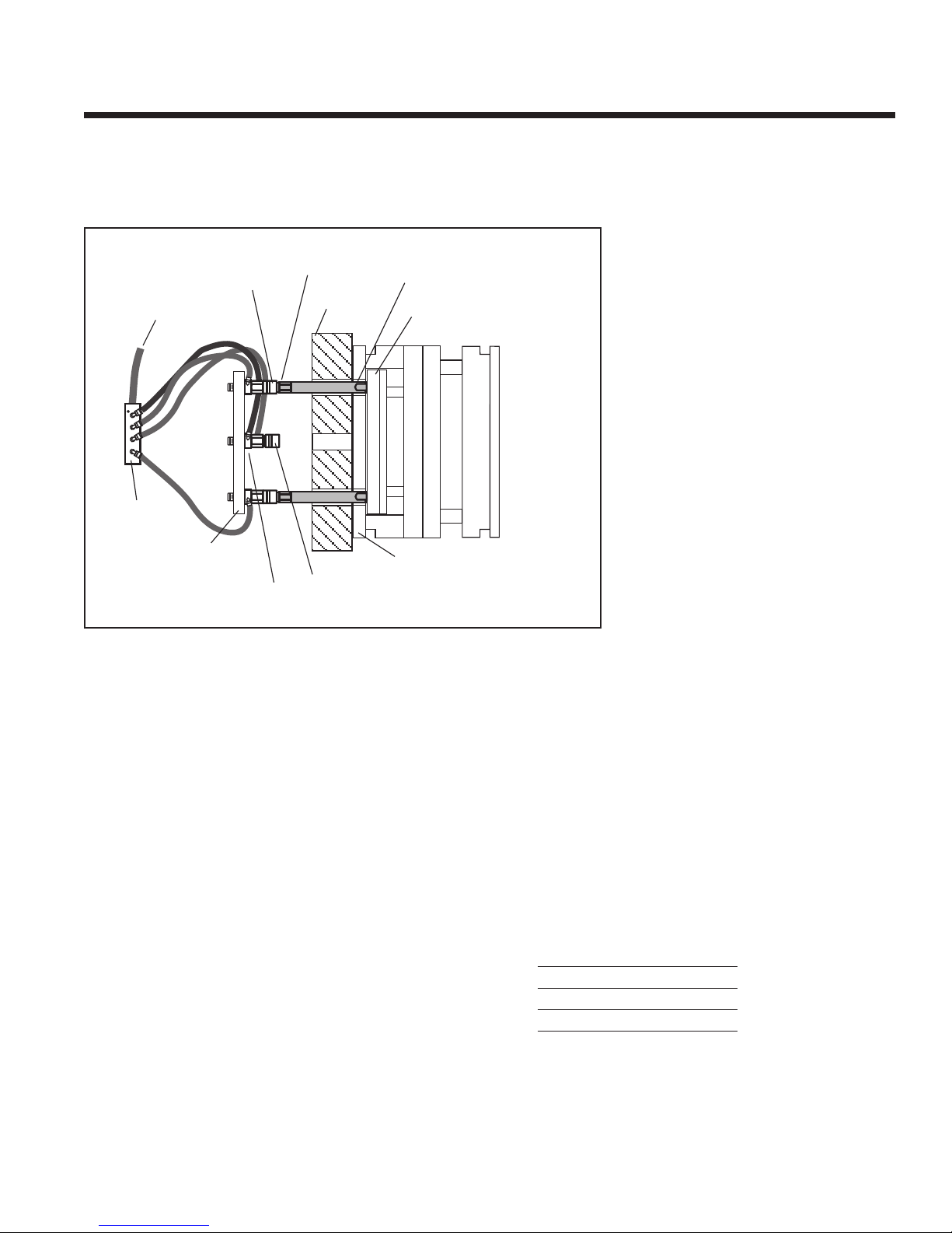
Couplers and Center Adapters on Press Ejector Plate
fo p esses with limited access to the back of the P ess Ejecto Plate.
Custom molde s using smalle p esses will benefit f om this installation.
Shop Air
Coupler
Pull Stud
Moving
Platen
Knockout Bar
(SpeedBar or Fixed Length)
Mold Ejector Housing
Press
Ejector Plate
Manifold
Accessory
Mold Ejector
Plate
Center Adapter
with Pneumatic Fitting
Unused Coupler
in Open Position
figure 4
The following installation instructions are for reference only.
Installation may vary depending on the application and
customer preferences.
1. Install the coupler with the center adapter into the press
ejector plate populating for the required molding machine
patterns (i.e. vertical, horizonal and/or center knockout
positions). Use thread-locking compound to prevent
movement during use.
2. Install pneumatic fitting to the center adapter per figure 4.
3. If using the manifold accessory, mount the manifold and
tubing so they do not interfere with moving parts.
4. Connect shop air lines to the pneumatic fittings that feed
the FasTie couplers. Couplers must be in the open
position (see figure 1) before connection to pull studs,
otherwise coupler damage will occur.
5. Install the pull stud onto the end of the knockout bar.*
6. Insert the knockout bar assembly in the moving platen.
7. ower the mold into position and clamp the A side
(stationary side) making sure the mold is square to the
machine.
8. Position the moving platen, providing clearance between
the platen and the mold, for installation of the knockout
bar assembly into the mold ejector plate.
9. Slowly position the moving platen against the mold,
observing the coupler and pull stud. Proper center
alignment and engagement are critical at this time.
10. Clamp the B side (moving side) of the mold to the platen.
Open the mold to safe ejection position.
11. Check that air supply to the coupler is off. If press ejector
plate and FasTie system are not set at machine zero, set
Machine Ejector Back setting to match Mold Ejector Back
position. Move the press ejector plate forward to connect
the coupler and the pull stud.
12. Tighten nuts to the press ejector plate (if using) after the
FasTie components are coupled. This helps alignment of
the FasTie system.
13. Maximum allowable center-to-center misalignment of
coupler and pull stud is below: (see figure 2)
1" HS ±3.5mm (±0.138")
1-3/8" ±5mm (±0.197")
2" ±6mm (±0.236")
3" ±5mm (±0.197")
14. Follow “Test Installation” procedure on page 6.
* 1” HS FasTie only: For installation using SpeedBar®
Adjustable ength Knockout bars, insert bars at step 5,
taking care to insure all bars are exactly the same length.
burger & brown engineering tel. 800-764-3518 3
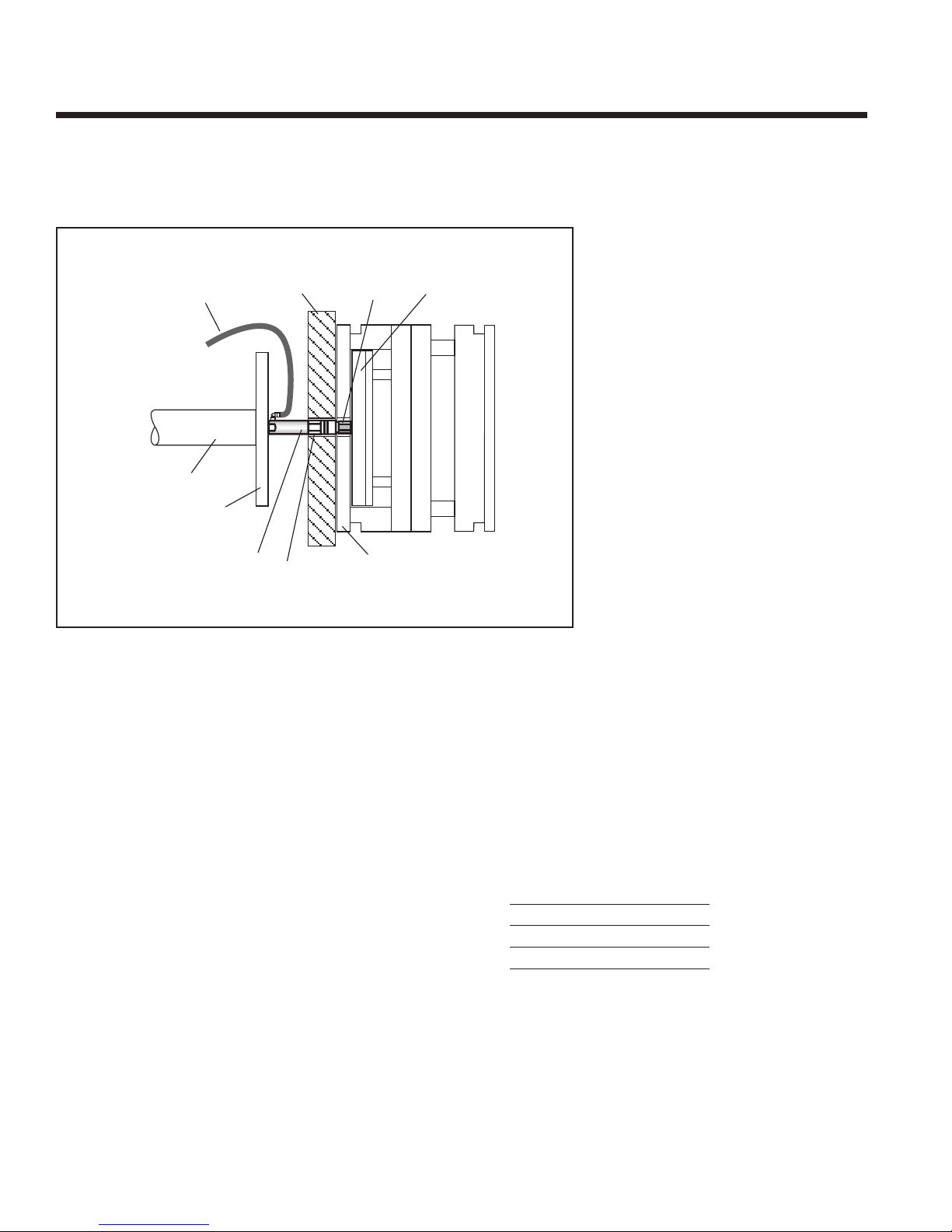
Coupler in Center Ejector Position
fo p esses with a cente ejecto , eplace the cylinde bolt with a
Cente Ejecto Ba o Cente Adapte and FasTie Couple .
The following installation instructions are for reference only.
Installation may vary depending on the application and
customer preferences.
1. Install the pull stud into the mold ejector plate per figure
5. Use thread-locking compound to prevent movement
during use.
2. Remove the Cylinder Bolt (if present) from the press.
3. Install the Center Ejector Bar or Adapter and FasTie
Coupler Assembly through the platen and tighten into the
cylinder.
4. ower the mold into position and clamp the A side
(stationary side) making sure the mold is square to the
machine.
5. Connect shop air lines to the pneumatic fitting for the
coupler. Coupler must be in the open position (see
figure 1) before connection to the pull stud, otherwise
coupler damage will occur.
6. Install the pull stud into the mold ejector plate.
7. Slowly position moving platen against the mold,
observing the coupler and pull stud. Proper center
alignment and engagement are critical at this time.
8. Clamp the B side (moving side) of the mold to the platen.
Open the mold to safe ejection position.
9. Check that air supply to the coupler is off. If press ejector
plate and FasTie system are not set at machine zero, set
Machine Ejector Back setting to match Mold Ejector Back
position. Move the press ejector plate forward to connect
the coupler and the pull stud.
10. Maximum allowable center-to-center misalignment of
coupler and pull stud is below: (see figure 2)
1" HS ±3.5mm (±0.138")
1-3/8" ±5mm (±0.197")
2" ±6mm (±0.236")
3" ±5mm (±0.197")
11. Follow “Test Installation” procedure on page 6.
Shop Air
Moving
Platen Pull
Stud Mold
Ejector Plate
Mold
Ejector
Housing
Coupler
Center Knockout Bar
or Center Adapter
with Pneumatic Fitting
Press
Ejector Plate
Cylinder
figure 5
4burger & brown engineering tel. 800-764-3518

burger & brown engineering tel. 800-764-3518 5
Couplers at the end of Ejector Bars
fo multiple molds in the same machine with the same ejecto
patte n and ejecto st okes
The following installation instructions are for reference only.
Installation may vary depending on the application and
customer preferences.
1. Install the coupler and the knockout bar assembly into the
press ejector plate populating for the required molding
machine patterns (i.e. vertical, horizonal and/or center
knockout positions). Use thread-locking compound to
prevent movement during use.*
2. Install washer, nut and pneumatic fitting per figure 6. Do
not tighten completely at this time.
3. If using the manifold accessory, mount the manifold and
tubing so they do not interfere with moving parts.
4. Connect shop air lines to the pneumatic fittings that feed
the FasTie couplers. Couplers must be in the open
position (see figure 1) before connection to pull studs,
otherwise coupler damage will occur.
5. Install the pull stud into the mold ejector plate.
6. ower the mold into position and clamp the A side
(stationary side) making sure the mold is square to the
machine.
7. Position the moving platen, providing clearance between
the platen and the mold.
8. Slowly position the moving platen against the mold,
observing the coupler and pull stud. Proper center
alignment and engagement are critical at this time.
9. Clamp the B side (moving side) of the mold to the platen.
Open the mold to safe ejection position.
10. Check that air supply to the coupler is off. If press ejector
plate and FasTie system are not set at machine zero, set
Machine Ejector Back setting to match Mold Ejector Back
position. Move the press ejector plate forward to connect
the coupler and the pull stud.
11. Tighten nuts to the press ejector plate after the FasTie
components are coupled. This helps alignment of the
FasTie system.
12. Maximum allowable center-to-center misalignment of
coupler and pull stud is below: (see figure 2)
1" HS ±3.5mm (±0.138")
1-3/8" ±5mm (±0.197")
2" ±6mm (±0.236")
3" ±5mm (±0.197")
13. Follow “Test Installation” procedure on page 6.
* 1” HS FasTie only: For installation using SpeedBar®
Adjustable ength Knockout bars, insert bars at step 1,
taking care to insure all bars are exactly the same length.
Press
Ejector
Plate
Knockout Bar
(SpeedBar or Fixed Length)
Coupler
Pull Stud
Ejector
Housing
Manifold
Accessory
Shop Air
Moving
Platen
Mold Ejector Plate
Nut and
Washer
figure 6

Test Installation
Verify Connection
1. Open the mold.
2. Activate the ejector system.
3. Observe the ejector pins. They should move forward and
return. Visually inspect the FasTie couplers to verify that
they are connected to the pull studs.
Verify Release
1. Apply air to the FasTie couplers.
2. Activate the ejector system.
3. Observe the ejector pins. They should move forward, but
not return.
Reconnect Couplers
1. Ensure that the FasTie couplers are in the open position
and the air pressure is off. See figure 1.
2. Move the ejector system forward
3. Return the ejector system.
4. Observe the ejector pins. They should be retracted
If the system is not connected properly, open the platen,
disconnect the couplers and pull studs, reconnect each ejector
position and re-test the installation.
Troubleshooting
Symptom
Ejector pins don’t move back when retracting ejector system;
FasTie does not connect
Corrective Action
• Confirm shop air is off during connection.
• Check coupler operation.
• Check pull stud and coupler alignment.
• Pneumatic valve or selector switch must allow residual air
pressure to dissipate when valve is “off”. Air pressure
when “off” is zero.
FasTie uncouples during ejector cycle • Check mold position in the machine. Mold must be
squarely installed and the FasTie coupler must not contact
the platen.
FasTie doesn’t uncouple • Check Knockout Bar length.
• Check that the mold is clamped squarely to the machine.
• Air pressure supply to the couplers should be 80 to 100 psi.
Check air lines and fittings for leaks or breaks.
• Ensure that couplers are not under tension when
disconnecting.
• Apply grease to couplers per “Maintenance” on Page 1.
Li ited Warranty
Seller warrants that this product supplied will conform to the description herein stated and that the product will be of standard
quality. This is the sole warranty made by Seller with respect to this product. Seller expressly disclaims any other express or
implied warranties, including, but not limited to, the implied warranty of merchantability and the implied warranty of fitness for
a particular purpose.
Seller shall not be liable for any cost or damages, whether direct, incidental or consequential, including, but not limited to, any
injury, loss or damage resulting from the use of this product, regardless of whether any claim for such cost or damages is based
on warranty, contract, negligence, tort or strict liability. The sole liability of Seller is limited to repairing or replacing this
product.
This warranty shall not apply to any products that have been repaired or altered by anyone other than Seller. The warranty shall
not apply to any products subject to misuse due to common negligence or accident, nor to any products manufactured by Seller
which are not installed or operated in accordance with the printed instructions of Seller or which have been operated beyond the
rated capacity of the goods. Seller states that the product’s useful safe life is 5 years. Actual life may vary widely depending on
operating environment such as temperature, pressure, and chemical exposure.
If corrective action fails to correct the problem,
please contact the factory.
6burger & brown engineering tel. 800-764-3518
Table of contents


