SmartGyro SG80 User manual

Operation manual
GYRO STABILIZER
SG80
en English

SG80 Operation Manual
Disclaimers:
All information, illustrations and specications in this manual are based on the latest informa-
tion available at the time of publishing. The illustrations used in this manual are intended to be
representative reference views only. Moreover, because of our continuous product improvement
policy, we may modify information, illustrations and/or specications to explain and/or exemplify
a product, service or maintenance improvement. We reserve the right to make any change at any
time without notice. Smartgyro is a registered trademark of Smartgyro s.r.l. in the United States,
the European Union, and the United Kingdom.
All Rights Reserved:
No part of this publication may be reproduced or used in any form by any means - graphic, elec-
tronic, or mechanical, including photocopying, recording, taping, or information storage and re-
trieval systems - without the written permission of Smartgyro s.r.l.
Please review and comply with the applicable laws and regulations of the international export
control regimes at the territory or country where the product and manual are intended to be im-
ported and used.
OPERATION MANUAL MODEL SG80
CODE 108OM405
All Rights Reserved, Copyright Smartgyro s.r.l.

i
SG80 Operation Manual
Content
Introduction . . . . . . . . . . . . . . . . . . . . . . . . . . . . . . . . . . . . . . . . . . . 1
Safety . . . . . . . . . . . . . . . . . . . . . . . . . . . . . . . . . . . . . . . . . . . . . . . . . .3
Safety symbols . . . . . . . . . . . . . . . . . . . . . . . . . . . . . . . . . . . . . . . . . 3
Safety precautions . . . . . . . . . . . . . . . . . . . . . . . . . . . . . . . . . . . . . . 4
General information . . . . . . . . . . . . . . . . . . . . . . . . . . . . . . . . . . . . 4
Before you operate. . . . . . . . . . . . . . . . . . . . . . . . . . . . . . . . . . . . . . 4
During operation and maintenance . . . . . . . . . . . . . . . . . . . . . . 4
Product overview . . . . . . . . . . . . . . . . . . . . . . . . . . . . . . . . . . . . . . 8
Overview. . . . . . . . . . . . . . . . . . . . . . . . . . . . . . . . . . . . . . . . . . . . . . . 8
System description. . . . . . . . . . . . . . . . . . . . . . . . . . . . . . . . . . . . . . 9
Function of Gyro Stabilizer. . . . . . . . . . . . . . . . . . . . . . . . . . . . . . 10
Component of SG80 Gyro Unit. . . . . . . . . . . . . . . . . . . . . . . . . . 11
Description of SG80 Gyro Unit . . . . . . . . . . . . . . . . . . . . . . . . . . 12
Description of control display. . . . . . . . . . . . . . . . . . . . . . . . . . . 13
Home page. . . . . . . . . . . . . . . . . . . . . . . . . . . . . . . . . . . . . . . . . . . . 14
Setting the control display. . . . . . . . . . . . . . . . . . . . . . . . . . . . . . 18
Roll Angle Monitor Page. . . . . . . . . . . . . . . . . . . . . . . . . . . . . . . . 21
Alarm Log Page. . . . . . . . . . . . . . . . . . . . . . . . . . . . . . . . . . . . . . . . 22
Performance Monitor Page . . . . . . . . . . . . . . . . . . . . . . . . . . . . . 24
Gyro stabilizer operation . . . . . . . . . . . . . . . . . . . . . . . . . . . . . . 26
Introduction. . . . . . . . . . . . . . . . . . . . . . . . . . . . . . . . . . . . . . . . . . . 26
Safety precautions . . . . . . . . . . . . . . . . . . . . . . . . . . . . . . . . . . . . . 26
Gyro Stabilizer Startup and Stabilization . . . . . . . . . . . . . . . . 27
Temperature derating . . . . . . . . . . . . . . . . . . . . . . . . . . . . . . . . . . 30
Gyro Stabilizer Shutdown . . . . . . . . . . . . . . . . . . . . . . . . . . . . . . 31
Emergency shutdown. . . . . . . . . . . . . . . . . . . . . . . . . . . . . . . . . . 32
Periodic maintenance . . . . . . . . . . . . . . . . . . . . . . . . . . . . . . . . . 33
Introduction. . . . . . . . . . . . . . . . . . . . . . . . . . . . . . . . . . . . . . . . . . . 33
Safety precautions . . . . . . . . . . . . . . . . . . . . . . . . . . . . . . . . . . . . . 33
Precautions. . . . . . . . . . . . . . . . . . . . . . . . . . . . . . . . . . . . . . . . . . . . 34
Periodic maintenance schedule. . . . . . . . . . . . . . . . . . . . . . . . . 35
Troubleshooting . . . . . . . . . . . . . . . . . . . . . . . . . . . . . . . . . . . . . . 38
Safety precautions . . . . . . . . . . . . . . . . . . . . . . . . . . . . . . . . . . . . . 38
Troubleshooting information . . . . . . . . . . . . . . . . . . . . . . . . . . . 38
Gyro system anomaly . . . . . . . . . . . . . . . . . . . . . . . . . . . . . . . . . . 39
Troubleshooting chart . . . . . . . . . . . . . . . . . . . . . . . . . . . . . . . . . 40
Specications . . . . . . . . . . . . . . . . . . . . . . . . . . . . . . . . . . . . . . . . . 44
Introduction. . . . . . . . . . . . . . . . . . . . . . . . . . . . . . . . . . . . . . . . . . . 44
SG80 Technical characteristics . . . . . . . . . . . . . . . . . . . . . . . . . . 45

ii SG80 Operation Manual

1
SG80 Operation Manual
It isn’t easy to outsmart the most powerful ele-
ment on earth. In fact, it takes brazen courage.
At Smartgyro, we push the limits of technology
to elevate the entire boating experience. Our
gyro stabilizers eliminate boat roll to make life’s
richest moments more extraordinary.
We believe the ultimate luxury is uninterrupted
time on the water. That’s why Smartgyro SG80
is designed to minimize not only unwanted
movement but also downtime during mainte-
nance. We are leading the way and raising the
bar for onboard comfort, safety, reliability, and
convenience.
To help you use your Smartgyro products for
many years to come, please follow these rec-
ommendations:
- Read and understand this Operation Manu-
al before you operate the gyro stabilizer to
ensure that you follow safe operating prac-
tices and maintenance procedures.
- Keep this Operation Manual in a convenient
place for easy access.
- If this Operation Manual is lost or dam-
aged, order a new one from your authorized
Smartgyro dealer or distributor.
- Make sure this manual is transferred to sub-
sequent owners. This manual should be
considered a permanent part of the gyro
stabilizer and remain with it.
- Constant eorts are made to improve the
quality and performance of Smartgyro
products, so some details included in this
Operation Manual may dier slightly from
your gyro stabilizer. If you have any ques-
tions about these dierences, please con-
sult your authorized Smartgyro dealer or
distributor.
Introduction

2 SG80 Operation Manual
3
SG80 Operation Manual
SAFETY
Smartgyro SG80 considers safety of great im-
portance and recommends that anyone that
comes into close contact with its products,
such as those who install, operate, maintain or
service Smartgyro products, exercises care and
common sense and complies with the safety in-
formation in this manual and on the machine’s
safety decals. Keep the labels from becoming
dirty or torn and replace them if they are lost
or damaged. Also, if you need to replace a part
that has a label attached to it, make sure you
order the new part and label at the same time.
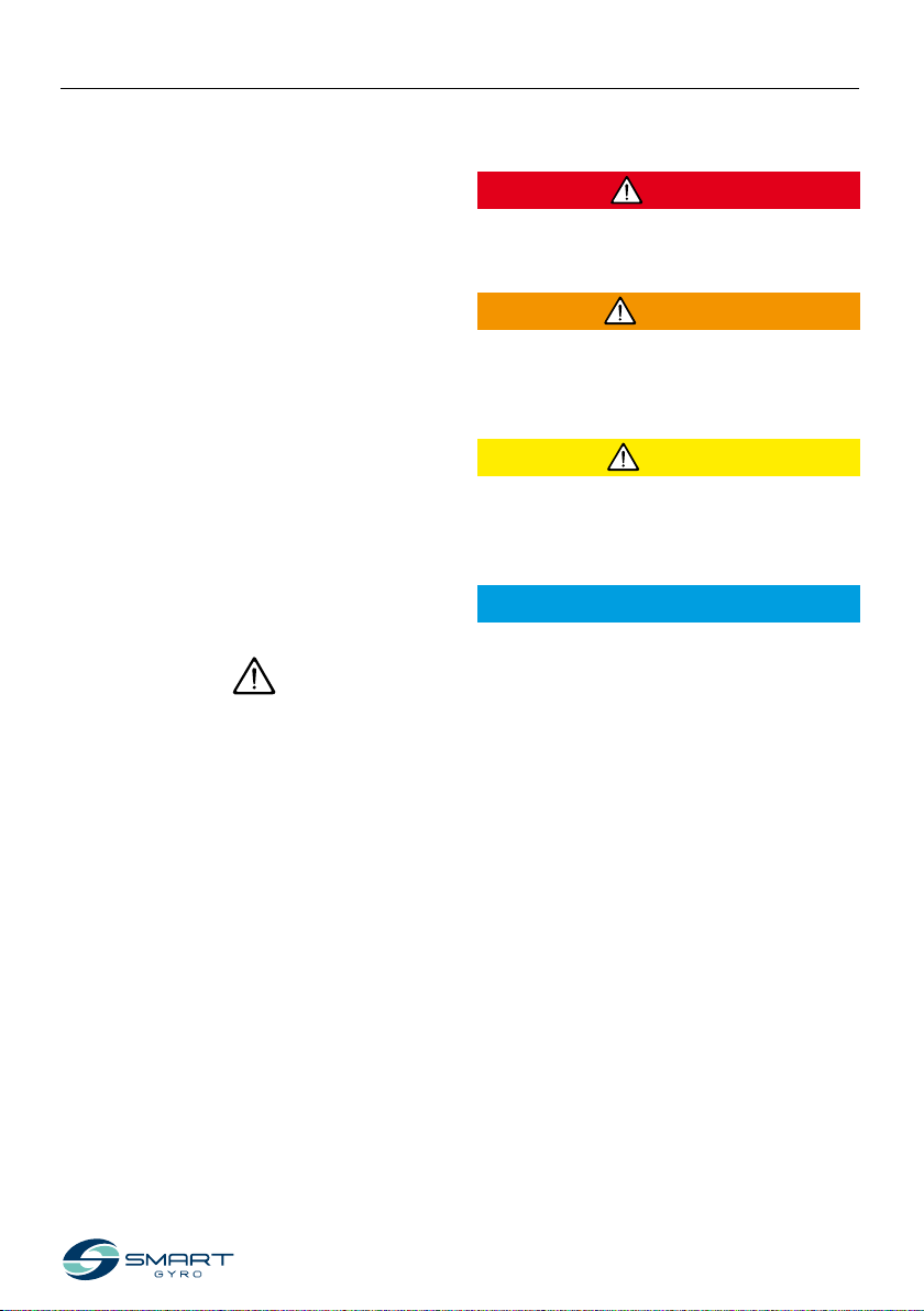
Safety symbols
These are the warning signs used in this manu-
al and on the product.
This safety alert symbol appears with most
safety statements. It means “attention, become
alert, your safety is involved!” Please read and
abide by the message that follows the safety
alert symbol.
DANGER
Indicates a hazardous situation which, if not
avoided, will result in death or serious injury.
WARNING
Indicates a hazardous situation which, if not
avoided, could result in death or serious in-
jury.
CAUTION
Indicates a hazardous situation which, if not
avoided, could result in minor or moderate
injury.
NOTICE
Indicates a situation which can cause damage
to the machine, personal property and/or the
environment, or cause the equipment to oper-
ate improperly.
Safety
4 SG80 Operation Manual
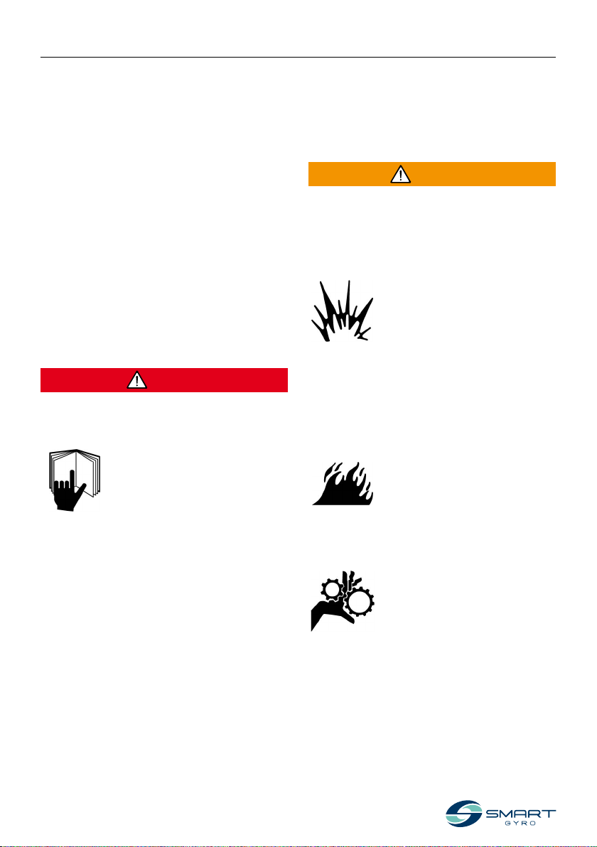
SAFETY
WARNING
The safety messages that follow have WARN-
ING level hazards.
Explosion Hazard
Keep ammable materials such
as gasoline out of the area
where the gyro stabilizer is in-
stalled.
Before operating the gyro sta-
bilizer, conrm that there are no ammable
materials such as gasoline around the gyro
stabilizer.
Fire Hazard
Undersized wiring systems can
cause an electrical re.
Sever Hazard
The gyro stabilizer may poten-
tially cause mechanical and
electrical hazards. For this rea-
son, never stay in close proximi-
ty to the gyro unit, and never
service it when electrical power is applied or
when the ywheel is running.
General information
There is no substitute for common sense and
careful practices. Improper practices or care-
lessness can cause burns, cuts, mutilation, as-
phyxiation, other bodily injury or death. This
information contains general safety precau-
tions and guidelines that must be followed to
reduce risk to personal safety. Special safety
precautions are listed in specic procedures.
Read and understand all of the safety precau-
tions before operation or performing repairs or
maintenance.
Before you operate
DANGER
The safety messages that follow have DANGER
level hazards.
Never permit anyone to perform
maintenance or operate the
gyro stabilizer without proper
training.
- Read and understand this Operation Man-
ual before you operate or service the gyro
stabilizer to ensure that you follow safe op-
erating practices and maintenance proce-
dures.
- Safety signs and labels are additional re-
minders for safe operating and mainte-
nance techniques.
- Consult an authorized Smartgyro dealer or
distributor for additional training.
Safety precautions
During operation and
maintenance
5
SG80 Operation Manual
SAFETY
WARNING
- Never remove the protection panels that
cover the gyro unit when the gyro stabilizer
is running.
- Maintenance activities must always be per-
formed by qualied technicians only when
power is disconnected and the ywheel is
stopped.
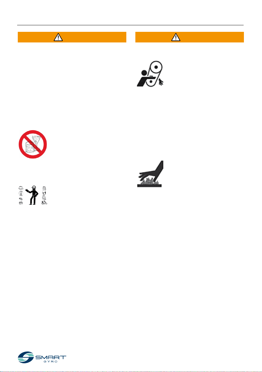
Alcohol and Drug Hazard
Never service the gyro stabilizer
while under the inuence of al-
cohol or drugs, or when feeling
ill.
Exposure Hazard
Always wear personal protective
equipment including appropri-
ate clothing, gloves, work shoes,
and eye and hearing protection
as required by the task at hand.
WARNING
Entanglement Hazard
When servicing the gyro stabi-
lizer, make sure that the gyro
system is not powered. It is pos-
sible for someone to activate the
gyro system without realizing
that someone is working on the gyro unit.
Never operate or service the gyro stabilizer
while wearing a headset to listen to music or
the radio because it will be dicult to hear the
warning signals.
Burn Hazard
Some of the gyro unit surfaces
can become very hot during op-
eration and shortly after shut-
down. Keep your hands and
other body parts

6 SG80 Operation Manual
SAFETY
CAUTION
Poor Lighting Hazard
Ensure that the work area is adequately illumi-
nated. Always install wire cages on portable
safety lamps.
Tool Hazard
Always use tools appropriate for the task at
hand and use the correct size tool for loosen-
ing or tightening machine parts.
Flying Object Hazard
Always wear eye protection
when servicing the gyro stabi-
lizer or when using compressed
air or high-pressure water. Dust,
ying debris, compressed air,
pressurized water or steam may injure your
eyes.
Coolant Hazard
Wear eye protection and rubber
gloves when you handle coolant
or hydraulic oil. If contact with
your eyes or skin occurs, clean
and wash it o immediately with clean water.
WARNING
Electrical Shock Hazard
- Inside the gyro unit
hazardous voltages are
present. For this reason the
cover must not be opened
when the gyro system is
running and AC power is connected. Also,
never disconnect the yellow/green
earthing/grounding cable, connected to
the ground stud.
- Before opening the cover be sure that the
AC mains supply is disconnected from the
gyro unit.
- Before operating the gyro stabilizer ALWAYS
ensure that the safety ground cable is se-
curely connected to the gyro base frame.
- The inverter box contains hazardous volt-
ages derived from the AC power line. When
inspecting the inside of the inverter box, be
sure to turn o the AC power supply.
- A potentially dangerous voltage is present
even if AC power is disconnected but the
ywheel is still rotating. Therefore, service
work on the inverter box is only permitted
when power is disconnected and the y-
wheel has come to a complete stop.
7
SG80 Operation Manual
SAFETY
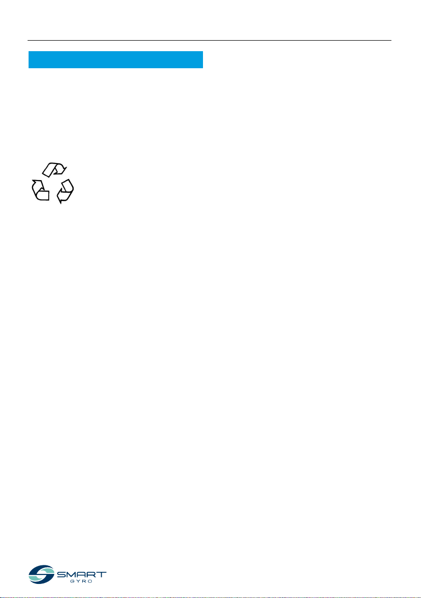
NOTICE
The safety messages that follow have NOTICE
level hazards.
Periodic maintenance prevents unexpected
downtime and helps extend the life of the gyro
stabilizer.
Always be environmentally re-
sponsible.
Follow the guidelines of the EPA or other gov-
ernmental agencies for the proper disposal of
hazardous materials such as coolant and hy-
draulic oil. Consult the local authorities or rec-
lamation facility.
Never dispose of hazardous materials by
dumping them into a sewer, on the ground, or
into groundwater or waterways.
Do not shut o the power or short the cables
while the gyro system is running. Damage to
the electrical system will result.

8 SG80 Operation Manual
PRODUCT OVERVIEW
Overview
Smartgyro SG80 is the gyro stabilizer of choice
for boats from 60–70 ft.
Ideal for both new builds and ret installations,
the stabilizer can be fully serviced on-board
the vessel without the need to lift it out for
maintenance, ensuring signicant savings in
time and cost.
For larger vessels, in order to increase the anti-
roll torque, more than one Smartgyro SG80 can
operate in parallel on the same boat. These
units work autonomously and there is no need
to synchronize them.
This manual, therefore, only outlines a single
unit installation, where the gyro stabilizer is
controlled by its own control device (the “Con-
trol display”).
Product overview

9
SG80 Operation Manual
PRODUCT OVERVIEW
System description
This gyro stabilizer contains the following units.
- SG80 gyro unit
- Control display
5
DC 24 V
6
64
3
1
4
2
5
AC 230 V 50-60 Hz
7
Figure 1
1. SG80 gyro unit
2. Control display
3. See water pump *1
4. Electrical connections (electronic control)
5. Electrical connections (power)
6. Hydraulic connections *1
7. Sea water intake
*1. Item not included in the scope of supply.

10 SG80 Operation Manual
PRODUCT OVERVIEW
Figure 2
1. Boat tilt
2. Precession angle
Function of Gyro Stabilizer
This gyro stabilizer is a device that creates an
anti-roll torque that reduces the tilting of the
boat using the gyroscopic principle.
Anti-roll torque is generated by the combined
eect of having a high-inertia ywheel rotat-
ing inside the gyro sphere and the sphere
tilting around the precession axis. The preces-
sion movement is automatically created by
the gyro, when subjected to the sea roll, and is
dynamically adjusted by the control unit, that
regulates the braking eect of two hydrau-
lic cylinders, to transmit the optimal anti-roll
torque to the boat.
1
3
33
3
2
44
2
1
1
3
33
3
2
44
2
1
3. Anti-roll torque
4. Bow

11
SG80 Operation Manual
PRODUCT OVERVIEW
Component of SG80 Gyro Unit
1. Heat exchanger
2. Vacuum pump
3. Pressure sensors
4. Accumulators
5. Manifold
6. Vacuum sensor
7. Gyro sphere and ywheel
8. Hydraulic cylinders
9. Precession angle sensor
10. Base frame
11. Lower bearing
12. Inverter box
13. Upper bearing
14. Glycol pump
15. Control box
16. Motor sealed sleeve
17. IR sensor (upper) sealed sleeve
18. IR sensor (lower) sealed sleeve
Figure 3
1234
9
11
12
17
18
16 6
7
13
14
15
10
5
6
7
8

12 SG80 Operation Manual
PRODUCT OVERVIEW
Description of SG80 Gyro Unit
The control unit monitors the system components and displays the information obtained on the
control display.
The following components are monitored by the control unit.
Name of component Description
Flywheel The ywheel rotates inside the gyro sphere.
It takes the ywheel about 45 minutes to accelerate from a stand-
still and reach top speed. It also takes about 120 minutes to decel-
erate from top speed to a complete halt.
Upper and lower bearings Because the upper and lower bearings support the ywheel rotat-
ing at high speed, they are subjected to heavy loads and high tem-
peratures. Therefore, the glycol pump circulates coolant to reduce
the temperature of these bearings.
Vacuum pump The vacuum pump creates a specic grade of vacuum state inside
the gyro sphere to minimize air resistance generated when the y-
wheel rotates.
Hydraulic cylinders Two hydraulic cylinders are used to brake and control the preces-
sion movement of the sphere.
When the user wants to lock precession, the system applies a brake
to the gyro sphere by blocking oil ow within the cylinders. In this
condition no antiroll torque is generated by the gyro.

13
SG80 Operation Manual
PRODUCT OVERVIEW
Description of control display
The control display is the interface between
the user and the operation of the gyro unit. It
is typically installed on the boat’s helm station.
When the system is powered (DC 24 V), the dis-
play turns on and the splash screen is displayed
(Smartgyro logo). After about 40 seconds since
power on, the Home page (Figure 5) appears.
The home page groups and displays the most
important parameters of the gyro unit.
Figure 4
The main purpose of the display is to activate,
control and monitor the gyroscope during its
operation.
In the case of an anomaly, the display unit au-
tomatically warns the operator of the failure
which has occurred, showing an anomaly mes-
sage on a dedicated alarm log page.
The control display is a touchscreen device
and can be operated by pressing the icons dis-
played on it.
Figure 5

14 SG80 Operation Manual
PRODUCT OVERVIEW
Figure 6
Home page
The following information elds are presented on the home page.
3
9
5
6
2
11
1
7
8
4 10
Display item Description
1 Power (ON/OFF)
icon
When the gyro system is powered, the outer circle of this icon is gray; when the
icon is pressed, the circle turns green, indicating that the system is powered (basi-
cally that the motor drive is on) and running. If for any reason the stabilizer unit
cannot be turned on, the circle remains gray.
2 Precession
lock toggle icon
When the ywheel is accelerating and has not reached a minimum velocity (set
at 55 % of top speed), the precession lock toggle icon has no eect on preces-
sion, which remains locked; this condition is signalled by the presence of yellow
circle around the icon. Once the ywheel rotation speed has reached 55 % of top
speed, the circle goes blue, and the functionality of the icon is enabled.
A red circle indicates that precession is locked and no antiroll torque is generated.
By pressing the icon, the circle is red and precession is locked.
Pressing the icon again, the outer ring becomes blue, precession is unlocked and
antiroll torque is generated (and so on, thereby toggling functionality).
3 Menu icon By pressing this icon, it is possible to log into the various pages of the menu.
See gure 17.

15
SG80 Operation Manual
PRODUCT OVERVIEW
Display item Description
4 Identication
number
Displays the identication number of the gyro currently selected. The stabilizer
identication number can be set in a password protected page of the Settings
menu.
In general, data presented on the various pages of the display refer to the gyro
whose ID is selected (and displayed) on this page.
5 Roll angle This information is derived from the IMU (Inertial Measurement Unit) inside the
control box and is presented in both digital and analogue form; digital data is in a
“two digits + sign” format. See“Indication of roll and pitch angles on page 16.
6 Precession angle
(gyro sphere
angular position)
Precession angle given in both digital and analogue.
In digital form, it is presented as the actual angle (in degrees) of the gyro sphere
with respect to the vertical.
In analogue form, it is represented by a blue bar that originates from the center
and goes to the left or the right depending on the angle of the sphere. See“Indi-
cation of precession angle” on page 17.
7 Speed indication Flywheel rotation speed given in both digital and analogue.
In digital form, it is shown as a percentage of top speed (“day” speed); when the
system is accelerating, this indication goes from 0 % to 100 % (if the system is in
“day” mode) or to 65 % (if in“night” mode).
In analogue form, it is shown as a circular dial, whose red pointer indicates the
actual speed, expressed as percentage of top speed.
8 Bearing
temperatures
The temperatures of both upper and lower bearing packs are presented in the
form of two curved segments whose length increases proportionally to the meas-
ured temperature.
9 Pressure of
hydraulic circuits
The two pressure values are presented here in the form of two curved segments
whose length is proportional to the pressure itself.
10 Local time
(hours, minutes,
seconds)
Hour information is stored in the battery-powered real-time clock inside the gyro’s
Control Unit. The local time can be set reaching the “Set time”option described on
page 18.
11 Gyro working state Indicates the current operating state (“mode”) of the stabilizer.
See table on page 25.

16 SG80 Operation Manual
PRODUCT OVERVIEW
Indication of roll and pitch angles
A positive roll is observed when the starboard
side of the vessel is angled upward (starboard
up) (Figure 7).
A positive pitch is observed when the bow of
the vessel is angled downward (bow down)
(Figure 8).
If the roll is positive, the semi-circular bar on the
Home page moves to the right (Figure 9).
Figure 9
A negative roll is observed when the port side of
the vessel is angled upward (port up) (Figure 10).
A negative pitch is observed when the bow of
the vessel is angled upward (bow up) (Figure 11).
If the roll is negative, the semi-circular bar on the
Home page moves to the left (Figure 12).
Figure 12
Figure 7
Figure 8
Figure 10
Figure 11
This manual suits for next models
1
Table of contents
Other SmartGyro Boating Equipment manuals


Popular Boating Equipment manuals by other brands


Zattini Group
Zattini Group bamar BTM 08 Use and maintenance instruction manual

Muir
Muir STORM VR 2500 manual

Attwood
Attwood 11930-4 Owner's instructions

SureShade
SureShade Power Bimini Installation and owner's manual

bamar
bamar PE instruction manual

Kingfisher
Kingfisher ECLIPSE Assembly and installation instructions


