Smartpond Filter User manual

Instruction manual
Instruction manual EBF / EBF ECO Page 1 of 19
11/2013
Table of Contents
1Read this first........................................................................................................................................... 1
1.1 Symbols and used terms........................................................................................................................ 3
1.2 Responsibilities ...................................................................................................................................... 4
2Technical Data ......................................................................................................................................... 5
2.1 Control unit box..................................................................................................................................... 5
2.1.1 Control elements............................................................................................................................... 5
2.1.2 Mounting of the control unit box...................................................................................................... 5
2.1.3 Power outputs................................................................................................................................... 6
2.1.4 Control unit circuit board .................................................................................................................. 7
3Model EBF................................................................................................................................................ 8
3.1 Application............................................................................................................................................. 8
3.2 Delivery form ......................................................................................................................................... 8
3.3 Installation............................................................................................................................................. 8
3.3.1 Mechanical installation ..................................................................................................................... 8
3.3.2 Electrical installation ....................................................................................................................... 11
3.4 Commissioning .................................................................................................................................... 11
4Local settings ......................................................................................................................................... 11
4.1 Running times...................................................................................................................................... 12
4.2 Float gauge .......................................................................................................................................... 13
5Optional accessories .............................................................................................................................. 13
5.1 Drying/Overflow protection ................................................................................................................ 13
5.2 Integrated immersing UV-C ................................................................................................................. 14
6Maintenance and servicing .................................................................................................................... 14
6.1 Cleaning of filter belt ........................................................................................................................... 14
6.2 Replacement of the filter belt ............................................................................................................. 16
6.3 Cleaning of the fine filter and pressure pump..................................................................................... 17
6.4 Cleaning of the float gauge.................................................................................................................. 17
6.5 Cleaning of the belt spraying nozzle.................................................................................................... 17
7Replacement / Guarantee...................................................................................................................... 18
7.1 Further instructions ............................................................................................................................. 19
Copyright: This instruction manual is the intellectual property of the firm AquaFil Teichfiltration. It may only be copied for installation purposes and for operating the Smartpond®Filter.
The Smartpond®Filter shall be used for its intended purpose of used.

Read this first
Symbols and used terms
Instruction manual EBF / EBF ECO page 2 of 19
11/2014
1Read this first
Application of this
instruction manual
This instruction manual provides the installer of this plant, its owner and
the expert personnel with some important information regarding
installation and maintenance of the plant and general information
regarding its safe operation.
Use
The described plant shall only be operated for its intended purpose of use
within the defined field of application. For filtration of special liquids and
any use in the industrial field, the manufacturer shall be consulted.
Intended purpose of use
The Smartpond® continuous belt filters are generally intended for use in
cleaning and filtration of solids from liquids. Field of application includes
industries, fish farming, sewage treatment plants and fish and swimming
ponds.
Liability
If the plant is operated for a purpose beyond the field of application or if
it is modified, it would no longer be considered in use for the intended
purpose. In such cases, the manufacturer will not accept any liability.
We recommend the settings ‘‘dry-run protection with S-version’’ and
‘‘overflow protection with G-version’’ for high pumping output.
Dismantling and
disassembling
The dismantling or disassembling of a Smartpond® filter plant shall only
be carried out by an authorised Smartpond® retailer or qualified
personnel or with their consent/instructions.
Safety
Before opening the terminal box cover, make sure to disconnect the
power cable from the mains!

Read this first
Symbols and used terms
Instruction manual EBF / EBF ECO page 3 of 19
11/2014
1.1 Symbols and used terms
Warning
This symbol gives a warning message which, if ignored, could lead to
injuries or substantial property damage
This warning message shall be taken seriously in any case!
Instruction
This symbol draws your attention to important information. When
ignored, damage to the plant or errors may be caused.
G-Model
Text or description which relates to the G-Model
(pumped version)
S-Model
Text or description which relates to the S-Model
(gravity version)
Plant
Complete Smartpond®Filter equipment as described in this instruction
manual.
Guarantee
For guarantee claims, it is important to leave the plant unmodified in its
original state and frost-proof (verifiable).
Any modification, adjustments, upgrading etc of the plant would lead to
loss of guarantee claims.
Owner of the plant
The person or firm that owns the plant and is responsible for its operation
and maintenance.
Skilled personnel
People who are trained for carrying out installation and maintenance
work. People who are aware of the potential dangers associated with use
of the plant and have the required tools and resources available at their
disposal.
Assembly work
All the work procedures and measures required for safe and proper
commissioning of the plant.
Error
The operating state which limits the operation of the plant or makes its
impossible.

Read this first
Responsibilities
Instruction manual EBF / EBF ECO page 4 of 19
11/2014
1.2 Responsibilities
Obligations of the
owner
The owner of the plant shall assure that:
the plant is kept in a safe operating state,
this instruction manual is provided to the expert staff members,
maintenance work is carried out on the plant after regular time
intervals.
Responsibility
Only expert personnel shall take charge of the following tasks:
installation
connecting the electrical components
setting the electrical components
the maintenance work
Manufacturer
Name AquaFil GmbH
Address Stuben14, 6030 Ebikon
Country Switzerland
Contact www.AquaFil.org
Local retailer /
Sub-supplier /
Distributer
(Factory label)
Technical Data
Control unit box
Instruction manual EBF / EBF ECO page 5 of 19
11/2014
2Technical Data
See www.AquaFil.org : Click on Filter and selected the desired type:
“Explosionszeichnung” (exploded assembly drawing)
2.1 Control unit box
2.1.1 Control elements
Warning
Before opening the terminal box cover, make sure to disconnect the
power cable from the mains!
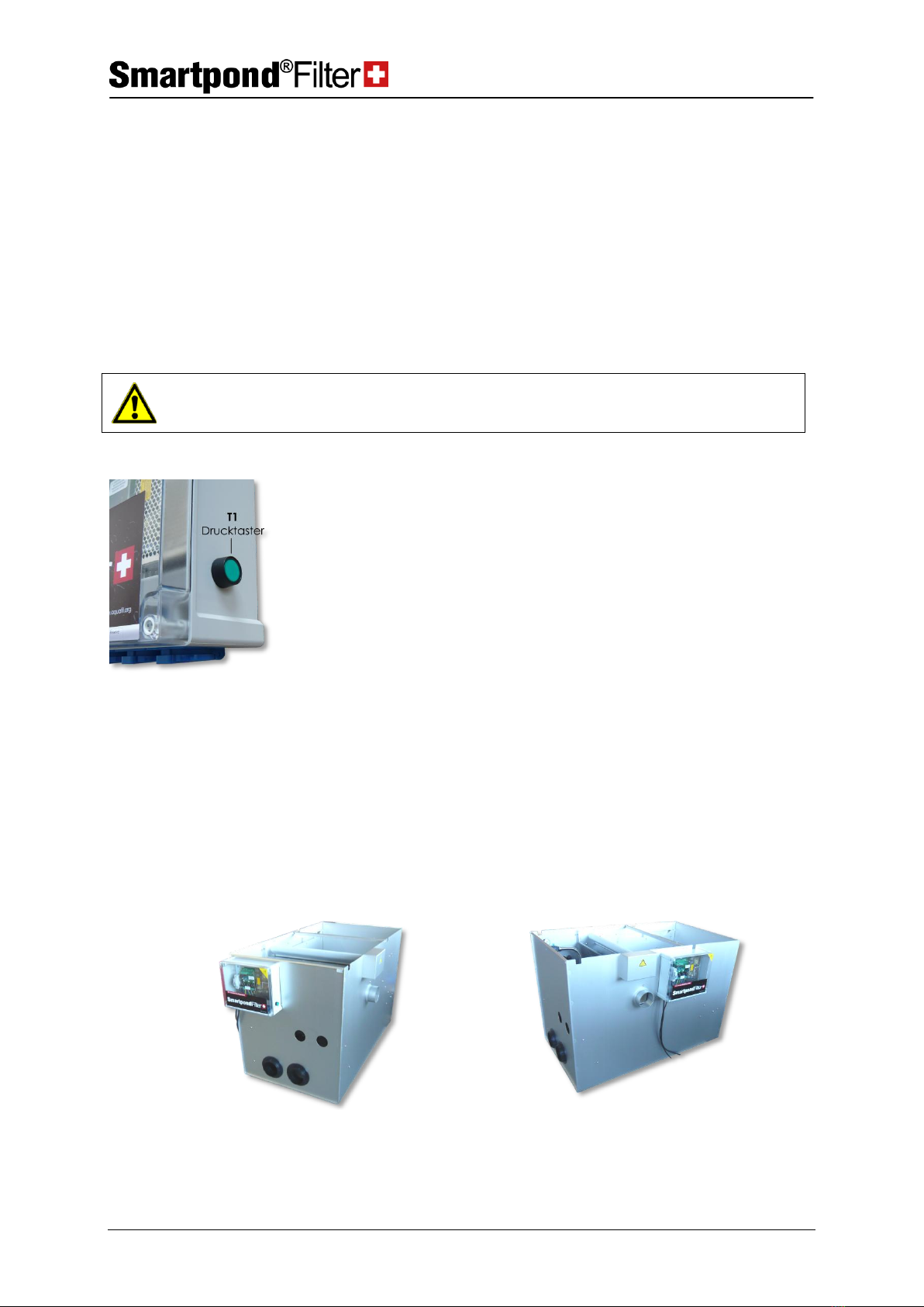
With the push button T1, the spraying pump AND the conveyor belt can
be manually controlled.
If only the conveyor belt has to be driven, the plug of the spraying pump
shall then be disconnected. As long as the button is pressed, the conveyor
belt will keep moving.
For testing the spraying pump (likewise with push button T1), disturbance
would not be caused normally if the conveyor belt moves alongside.
If only the spraying pump has to be tested, the plug can be inserted into
the spare power socket or the plug from the engine of the conveyor belt
has to be removed (for this, the cover box must be removed from the
engine first).
2.1.2 Mounting of the control unit box
The screws for mounting are provided in the control unit box.
For mounting the control unit box in the plant, there are two possible
ways to proceed:
Pos. front
Pos. right

Technical Data
Control unit box
Instruction manual EBF / EBF ECO page 6 of 19
11/2014
2.1.3 Power outputs
Lower side of the control unit box
At the lower side of the control cabinet, the cable outputs are visible on
the left side (L1 –L5):
L1
Lead for control unit box
Please insert in a 220VAC socket, which is secured with a FI protective
switch.
L2
Lead for belt drive
This cable is connected with the 24VDC motor in the motor box through
the 2 pole crimp connector.
L3
Float gauge sensor
With this 2 pole connector, the float gauge level B1 is connected through
the soldered 2 pole socket (insert and tighten the connecting nuts
securely).
L4
Option: Dry running/
Overflow protection
When the option ‘‘Dry running / Overflow protection’’ is selected, the
float gauge B4 is connected with this 2 pole connector through the pole
soldered socket (insert and tighten the connecting nuts securely).
L5
Option UV-C Switch
When the option UVC-circuit is ordered, the protective switch B2 is
connected with this 2 pole connector through the soldered 2-pole socket
(insert and tighten the connecting nuts securely).
Attention
When the leads L3 to L5 are plugged in, it shall be made sure that the
correct signal generator (float gauge, switch etc.) is connected to the
respective connector.

Technical Data
Control unit box
Instruction manual EBF / EBF ECO page 7 of 19
11/2014
2.1.4 Control unit circuit board
On the control unit circuit board, several LEDs (H1-H6) are available for
control purposes. They are visible all the time through the closed
transparent cover of the control unit box:
Picture control LED’s
H1
24V
Supply voltage 24VDC
(must light up during operation)
H2
3.3V
Internal circuit board voltage 3.3VDC
(must light up during operation)
H3
Float gauge sensor
Lights green when the float gauge sensor (B1) is active.
H4
Pump
Lights green when the power socket output for ‘‘spraying pump’’ is
triggered/activated.
H5
Belt drive
Lights green when the output for belt drive is triggered.
H6
Error
Lights red when the belt drive motor overloads (after 5 attempts).
Reset error by pushing the manual control (push button T1 –page 5)
Model EBF
Application
Instruction manual EBF / EBF ECO page 8 of 19
11/2014
3Model EBF
3.1 Application
The Pumped version is ideal for koi pond and pond owners who have
installed a pump directly in their pond or in a collecting chamber and
pump the contaminated water into the filter. In this system the outlet of
the biological stage lies above the pond level. The water flows back into
the pond according to the principal of gravity.
The Gravity version is suitable for koi and pond owners who have
installed floor drains and/or float gauges in their pond. With this system,
the pond water flows directly through large pipes into the Smartpond®
filter by gravity. With a pump the cleaned water is again pumped back
into the pond.
3.2 Delivery form
The plants are delivered in completely assembled state.
The unused tank ducts can be sealed from inside with silicone and the
discs delivered alongside.
(see picture)
3.3 Installation
3.3.1 Mechanical installation
Instruction
The filter must be installed frost-free. If this is not done, no guarantee can
be claimed for damage cause by frost.
The filter must be positioned on a plain and solid foundation. Ideally, the
filter is placed on a thin Styrofoam /Styrodur layer. This would provide an
even surface and prevent scratches from appearing on the filter base.
Instruction
It must be assured that the backflow to the pond takes place through an
adequate number of pipes to prevent build-up of backwater in the filter.
Instruction
The upper edge of the filter is positioned 10 cm higher than the pond
water level. 10 cm is the minimum value and the filter shall not be
positioned lower than this.
In order to comply with this value, the pond shall have an overflow outlet.
If the filter is installed more than 10 cm above the water level in the
pond, the filtration efficiency will fall. Ideally, the maximum water level in
the pond shall be limited through an overflow outlet.
Filter inputs
The filters are equipped with welded pipe sockets for D110mm pipes.

Model EBF
Installation
Instruction manual EBF / EBF ECO page 9 of 19
11/2014
Every intake point to the filter shall be fitted with slide or ball valves.
For the G-Version or high pumping outputs, the water shall be distributed
in several inflow pipe sockets so that it can reach the filter quietly.
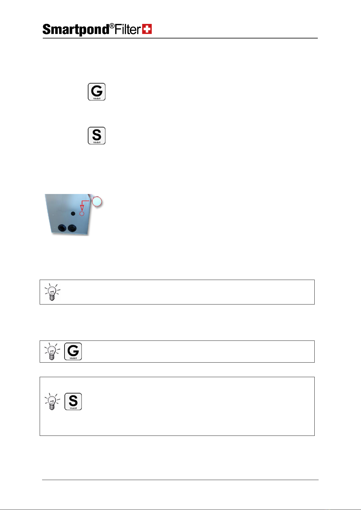
Filter outputs
The Smartpond® continuous belt filters are delivered together with
D 110mm tank screws for the return flow. Further a drill hole (or even a
second one depending on the model) is present for screw joints with D
75mm. The PVC screw joint for this is not provided in the delivery
package.
In the PVC tank screws, short pipe fittings shall be bonded onto so that
pipes having a sealing ring can easily be pushed onto. Like this
disassembly of the inlets is assured without having to saw off any pipes.
Instruction
It shall be assured in particular that the water feedback system to the
pond is large enough to prevent build-up of backwater in the filter.
In order to maintain a certain water level in the bio-stage for biological
organisms, the bio-stage outlets are turned upwards with a 90° elbow,
and with a T-joint, the pond is re-conected. The height relations of the T-
joint determine the water level in the bio-stage (see picture).
T-Drain pipe to the pond
(not included in the delivery
package)
The height from the
ground to centre of the T-
drain pipe shall be set to
approx. 40–45 cm (30-35cm
for EBF ECO).
Overflow pipe
In the filter, an overflow pipe shall also be installed with a height of up to
65 cm above ground level. This serves as overflow prevention in case if
the filter basket in the bio-stage is clogged with sludge. The safety
opening at the top shall be not covered with any filter basket or the like
but must rather remain completely open.

Model EBF
Installation
Instruction manual EBF / EBF ECO page 10 of 19
11/2014
Positioning of the pond
pumps
Feed pumps can be set up In the bio-stage or outside the filter ‘‘dryly’’.
In order to keep biological organisms away from the pumps, a slotted pipe
can also be delivered optionally.
Dirty water drain
The dirty water drain is present at the right side of the filter. Please take
this into consideration during the planning.
Dirty water drain with 110 mm elbow
Setting of the safety overflow
With the overflow plate mounted in the filter, emergency water supply can
be adjusted for the pumps and biological life.
Function
If the contaminated filter belt cannot be driven further for some reason,
the water level in the filter module will increase and the pond water will
rise above the overflow plate in the bio-pond.
Setting
The overflow slit shall be kept as wide as possible. The overflow edge of
the overflow plate is positioned around 1 cm above the water level in the
filter (before the flushing process begins) and tightly screwed. The factory
default setting is 13 cm as shown in the picture below.

Local settings
Commissioning
Instruction manual EBF / EBF ECO page 11 of 19
11/2014
3.3.2 Electrical installation
Warning
Before handling the filter, the power plug shall be drawn out of the main
power supply socket for safety reasons.
The filter is delivered in mounted and operational mode. The control unit
box must be protected from rain/water and moisture and hung up in frost-
free surroundings.
Warning
FI switch: With regard to electrical installation of the plant, it must be
assured that the power supply is passed through a residual-current circuit
breaker
The switch in the control unit box is designed for a total of 16 A of current.
Instruction
In order to guarantee the safety functions, the pond pumps and pressure
pump as well as the optional immersing UV-C shall be directly connected to
the control unit box.
3.4 Commissioning
After the filter has been properly positioned, all supply and return pipes
have been installed and ca. 40cm water has been allowed to enter, the
power cable can be connected with the mains.
4Local settings
Fuses for the power sockets in the control unit box
F2 spraying pump –T 8A
F3 UVC –T 1.25A
F4 pond pump –T 5A
Warning
Only use slow-blow fuses (5x20mm)!

Local settings
Running times
Instruction manual EBF / EBF ECO page 12 of 19
11/2014
4.1 Running times
The feed times etc are adjusted in the control unit box using three
potentiometers according to the conditions of the local pond area.
Warning
Before the control unit box is opened, the supply cable is disconnected
from the power socket!
3 Potentiometers
On the Smartpond® circuit board, there are three potentiometers with the
following designations:
P1 Left
P2 Centre
P3 Right
Delay of the pump
Waiting time
Running time
P1 P2 P3
Functioning of the control unit
Start of the cleaning
cycle
B1 (float gauge)
When the fault gauge sensor B1 is pressed, the cleaning cycle begins. The
spraying pump is triggered for this purpose (Output A2 = power socket for
spraying pump).
Delay of the pump
P1
After a fixed delay time of 1 sec, the time P1 begins (delay of the pump)
which can be adjusted between from 0.1 to 10 sec.
Default setting ex factory: 0.1 Sec. = minimum; left-hand limit stop
After this time lapses, the conveyor belt starts moving (Lead L2)
Running time of the
conveyor belt
P3
The conveyor belt runs for a specific running time (P3) which can be varied
between 2 and 20 sec.
Default setting ex factory: ca. 11 sec. = Mean (ca. 12:00)
End of the cleaning
cycle
After the P3 time period lapses, the conveyor belt stops to move. But the
spraying pump operates for a fixed programmed time of 1 sec longer so
that no dirt remains on the belt or reaches the clean bio-chamber.
Waiting time till the
next cycle possible
P2
After the spray nozzle stops, the delay time P2 (waiting time) begins, which
can be varied between 5 and 30 sec.
Default setting ex factory: 30 sec. =max; right-hand limit stop
After the waiting period has passed, a new cleaning cycle can begin (if the
float gauge sensor is activated).

Optional accessories
Float gauge
Instruction manual EBF / EBF ECO page 13 of 19
11/2014
4.2 Float gauge
The float gauge (B1) is firmly installed at the top in the filter module and
its height can easily be adjusted.
For the gravity system version of the plant, the float gauge (B1) is
positioned below in the bio-pond. By moving the support pipe, this can be
vertically displaced. In this way, the water level in the bio-pond is defined.
With a water level above the slotted overflow plate, the noise of the
water can be largely reduced.
Fault gauge
(B1) Fault gauge
(B2) - Drying/Overflow protection
G-Version S-Version
5Optional accessories
5.1 Drying/Overflow protection
For this option, a second fault gauge is also installed (B2).
For the Pumped version, the second fault gauge (B2- recognisable at the
external black floating body) is mounted at the top part of the filter
chamber which switches the pump off before the filter overflows
(overflow protection)!
If the water level falls below the level of the second float gauge (B2), the
pump and immersion UV-C will be switched off. In this way, the pump
and the biological life in the water will not dry up (dry-running
protection).
The UV-C is switched on 20 seconds after restarting regular operation.
Function
These protection options provide additional protection to your pond and
pump.
Pumping output
For pumping output above 40,000l/H, the option ‘‘overflow protection’’ is
Maintenance and servicing
Integrated immersing UV-C
Instruction manual EBF / EBF ECO page 14 of 19
11/2014
>40.000 l/h
highly recommended for all Pumped models!
If the overflow protection system has not been installed, the manufacturer
will reject any claims for damage arising through pumping out/dry of the
pond.
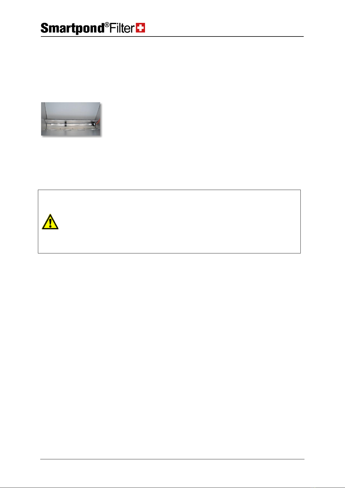
5.2 Integrated immersing UV-C
The Smartpond® immersing UV-C can directly integrated in the filter. For
this purpose, a UV-C belt protection plate shall be built in since otherwise,
the filter belt may be damaged by the UV-C rays.
Connection
The Smartpond® immersing UV-C is connected at the control unit box.
Option
The filter can optionally be equipped with a UV-C switch-off feature.
Through this, the immersing UV-C will automatically switch off on
removal of the protective cover.
Warning
If the additional option “UV-C disconnection’’ has not been selected and
the filter is accessible to third parties, the owner of the plant shall ensure
that adequate safety measures are in place on-site in order to rule out
the possibility of UV-C irradiation.
Never lay down the immersion UV-C on the filter belt. It shall only be
placed in the UV-C holder specifically designed for it. The material can get
damaged through UV-C exposure!
6Maintenance and servicing
6.1 Cleaning of filter belt
Depending on the degree of contamination, the throughput volume on
the filter belt may be reduced after some time or the rinsing water
consumption may be increased since a bio-film or lime deposit forms up
on the filter belt.
A narrow strip of dirt may be formed on the filter belt in the direction of
movement due to blocking of a belt spraying nozzle. In this case, the
nozzle has to be cleaned (see 6.5 Cleaning of belt spraying nozzle).
The filter belt can be sprayed and washed up with the following
detergents according to the manufacturer:
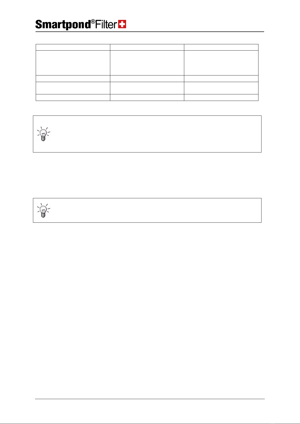
Here is an overview of the resistance of the polyester filter belt fabric to various detergents (details provided
by the manufacturer):
Maintenance and servicing
Cleaning of filter belt
Instruction manual EBF / EBF ECO page 15 of 19
11/2014
Detergent
Concentration
Resistance
Hydrochloric acid (HCl)
5 %
good
16 %
optimal
20 %
limited
> 35 %
not resistant
Citric acid (C6H8O7)
100 %
very good
Table vinegar
100 %
Very good (our
recommendation)
Hydrogen peroxide (H2O2)
3 %
Very good
Instruction
The selected detergent shall be applied and allowed to have effect for at
least 15 minutes. The filter belt should be as dry as possible.
The water level in the bio-pond should lie below the filter stage (filter
belt).
High-pressure cleaner
The belt can cleaned with high pressure (max. 120 bar) of cold water with
a distance of more than 15 cm, but without any guarantee.
Instruction
The use with a high-pressure cleaner is not guaranteed by the belt
manufacturer and can be carried out at own risk. However, we have
obtained some good results for it in extensive tests.
Maintenance and servicing
Replacement of the filter belt
Instruction manual EBF / EBF ECO page 16 of 19
11/2014
6.2 Replacement of the filter belt
The filter belt only needs to be replaced when it has been mechanically
damaged or possesses a defect caused by external influences.
Instruction
Draw out the power cable so that the belt does not run unintentionally!
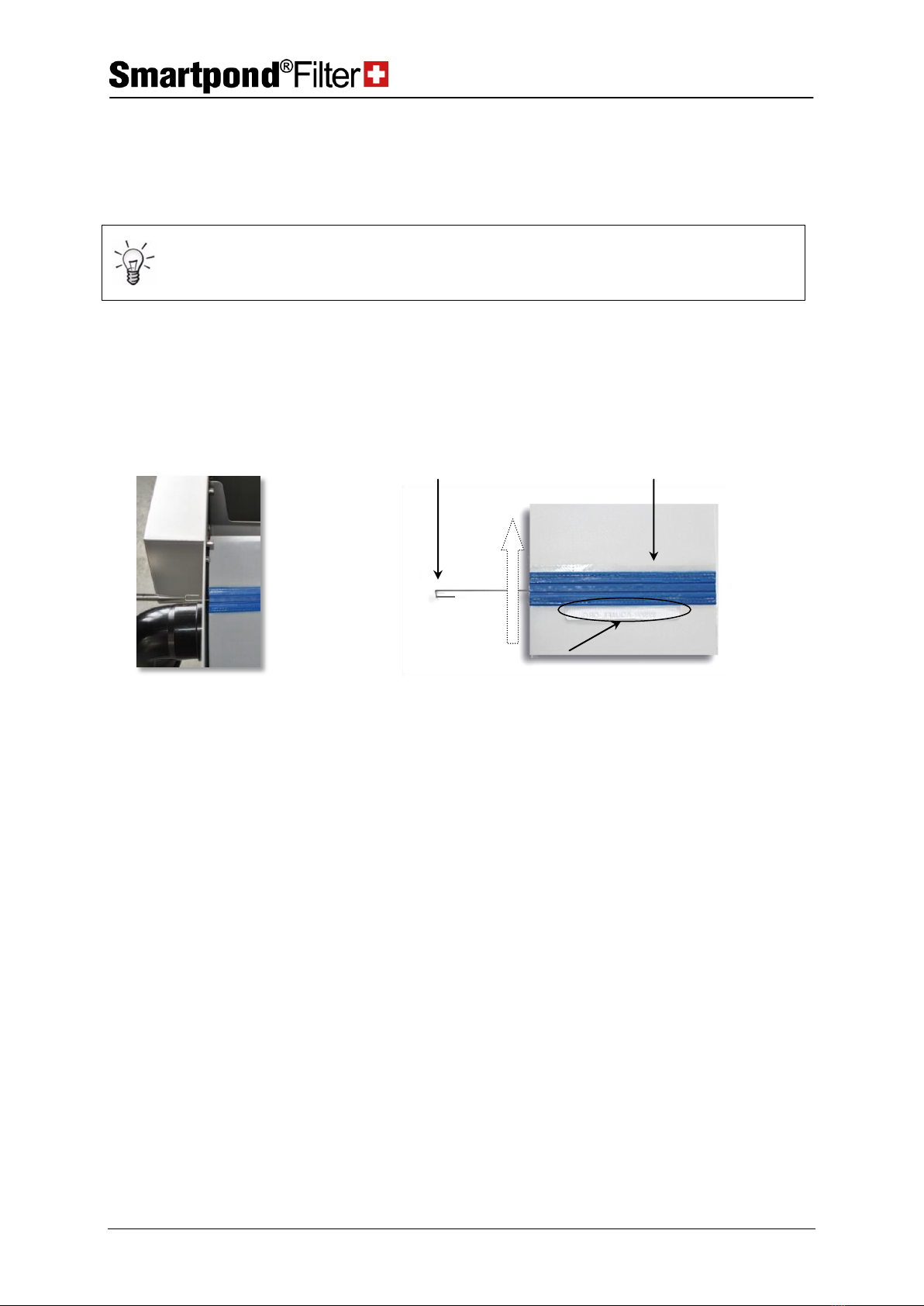
Insert the belt such that the tag (3- if present) does not get caught in (4,
see dotted arrow for direction of belt movement).
Connected belt
Position the blue quick-
release lock
Carry the belt forwards till the blue quick-release lock (2) reaches the
lateral opening (1). If there is no water on the belt, it can be positioned
accurately at the tag with the hand (2).
(1) Lateral opening
Remove the connecting
wire
Remove the connecting wire (4) of the belt from the side through the
lateral opening (1) (do not draw out the belt yet).
Move in a new belt
First clean the lock thoroughly and connect the quick-release lock side of
the old belt, on which the tag (2-if present) is found with the lock of the
new belt (see below ‘‘connecting the belts’’). Pull out evenly at the other
(open) side of the old belt till the end point of the new filter belt has
reached the opening (1). Like this the new belt will be easily guided
through. The connecting wire shall now be removed and the old belt can
then be separated from the new one.
Torn belt
If the belt is no longer connected for some reason, the new belt shall then
be ‘‘threaded up’’ manually.
Remove the belt
The no longer connected filter belt shall be removed so that the black
conveyor belt becomes visible.
Preparation
Attach a string or the like to the right and left side of the black conveyor
belt (e.g. through gluing or tying up). Control the belt feeder such that the
circular part at the top becomes visible/accessible once again
Threading up the filter
Attach the new filter belt to the threads and pull it carefully around the
(2) Blue quick-release lock
(4) Connecting wire
(3) Label
(5) Laufrichtung

Maintenance and servicing
Cleaning of the fine filter and pressure pump
Instruction manual EBF / EBF ECO page 17 of 19
11/2014
belt
black conveyer belt till it comes out at the top end. The strings can be
easily attached to the inserted connecting wire.
Connecting the belt
1. Position the start and end points of the belt in front of the opening
(1) at the side wall of the filter.
2. Insert the connecting wire to the belt through the lateral opening in
such a way that the blue teeth of the ends link together.
3. The angled piece of wire shall be inserted to the other side/loop (see
picture)
6.3 Cleaning of the fine filter and pressure pump
Filter basket
The rinse water for the filter belt is obtained from the bio-pond. The
pressure pump has a filter basket which can retain large wastes.
Fine filter
The fine filter retains all particles larger than 1/10mm. Through the
double safety offered, the spraying nozzles can hardly become blocked.
The fine filter (black Y-filter) has a cover cap at its end which can be
unscrewed for backwashing of the fine filter. After taking off the cover
manually begin the rinsing process in order to flush and clean the fine
filter. Protect yourself from splashes (e.g. through connection with a
hose). The complete sieve may also be removed and cleaned. The fine
filter should be examined after every 3 months.
6.4 Cleaning of the float gauge
It is advisable to check the float gauge after regular intervals of time and
to remove any dirt if necessary. For this purpose, the float gauge is drawn
out of the pipe together with its cap, rinsed with water and put back in
place again.
6.5 Cleaning of the belt spraying nozzle
Special anti-lime nozzles are used. The belt spraying nozzles are
positioned below the Plexiglas lid in front of the filter belt. You can check
the functioning of the flushing nozzles by slightly raising the Plexiglas lid.
Remove the spraying
nozzle
Screw out the blue spraying nozzle from the PVC pipe.
Clean the nozzle
Remove the accumulated dirt from the nozzle opening with a thin object

Replacement / Guarantee
Cleaning of the belt spraying nozzle
Instruction manual EBF / EBF ECO page 18 of 19
11/2014
(e.g. thin needle).
Insert the nozzle
When the nozzle is being inserted, it shall be made sure that the thread is
not overtightened.
Non-return valve
A non-return valve is present beside the manometer which prevents
dripping of water from the spraying nozzle when the water level is high in
the pond.
Water nozzle, Rinsing
channel
Another nozzle directed inwards facilitates the efficient transport of dirt
and contaminated water away from the system into the dirt outlet
channel.
Instruction
The opening of the nozzle is very delicate and it shall not be damaged!
The nozzles must be aligned to each other at a slightly slant angle so that
the ‘‘fan beam’’ overlaps and covers a large area (see picture).
Alignment / Angle of the flushing nozzles
7Replacement / Guarantee
Only original replacement parts of the firm AquaFil GmbH shall be used.
In case of improper installation, especially due to non-compliance with
the difference in the installation height of the S-Filter to the water level of
the pond, the manufacturer will not accept any claims for damage
resulting from it.
For defects which arise during and after the winter season, a guarantee
claim cannot be taken into consideration, if the plant has not been
adequately protected against temperatures lower than zero degrees.
The following wear parts are excluded from the guarantee:
Filter belt
Spraying nozzles
Fine filter insert

Replacement / Guarantee
Further instructions
Instruction manual EBF / EBF ECO page 19 of 19
11/2014
7.1 Further instructions
Instruction
The client is responsible for a safe installation of the G-versions on-site.
For pumping outputs above 40,000l/h, the installation of the option
‘‘Overflow protection’’ is mandatory. Without its installation, the
guarantee will be considered void.
The suction area of the pressure pumps must remain free in order to
avoid blockage or feeding of the pump through an air diffuser.
EBF 1200S
The float gauge shall not be positioned deeper than at its initial position
at the time of delivery.
The client would be considered responsible that the pond cannot be dried
out in case of a defect.
AquaFil GmbH draws attention to this danger and declines any liability in
the event of damage.
Table of contents
Other Smartpond Lawn And Garden Equipment manuals


Popular Lawn And Garden Equipment manuals by other brands


OCHIAI
OCHIAI EH-25SK owner's manual

Wolf Garten
Wolf Garten LI-ION POWER FINESSE 30 R Original operating instructions

juwel
juwel BIOSTAR PROTECT 2000 Assembly instructions

Zipper Mowers
Zipper Mowers ZI-RD300 user manual

ST. SpA
ST. SpA SPS 700 AE Operator's manual

Gardena
Gardena SR 1600 operating instructions


