manuals.online logo
Brands
  1. Home
  2. •
  3. Brands
  4. •
  5. SMC Networks
  6. •
  7. Switch
  8. •
  9. SMC Networks PS1000 User manual

SMC Networks PS1000 User manual

This manual suits for next models

2

Other SMC Networks Switch manuals

SMC Networks 6726AL2 - annexe 1 User manual

SMC Networks

SMC Networks 6726AL2 - annexe 1 User manual

SMC Networks 6824MPE INT - FICHE TECHNIQUE Programming manual

SMC Networks

SMC Networks 6824MPE INT - FICHE TECHNIQUE Programming manual

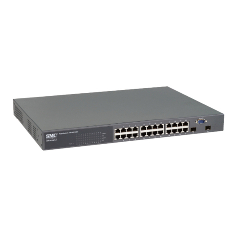
SMC Networks SMC6724L2GLSC User manual

SMC Networks

SMC Networks SMC6724L2GLSC User manual

SMC Networks TigerAccess SMC7824M/FSW User manual

SMC Networks

SMC Networks TigerAccess SMC7824M/FSW User manual

SMC Networks SMC6824M User manual

SMC Networks

SMC Networks SMC6824M User manual

SMC Networks SMC8606SX User manual

SMC Networks

SMC Networks SMC8606SX User manual

SMC Networks ZSE2 Series User manual

SMC Networks

SMC Networks ZSE2 Series User manual

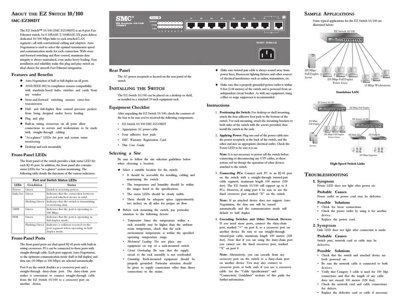
SMC Networks EZ Networking SMC-EZ108FDT User manual

SMC Networks

SMC Networks EZ Networking SMC-EZ108FDT User manual

SMC Networks ISE79S L2 Series User manual

SMC Networks

SMC Networks ISE79S L2 Series User manual

SMC Networks PF2D5 Series User manual

SMC Networks

SMC Networks PF2D5 Series User manual

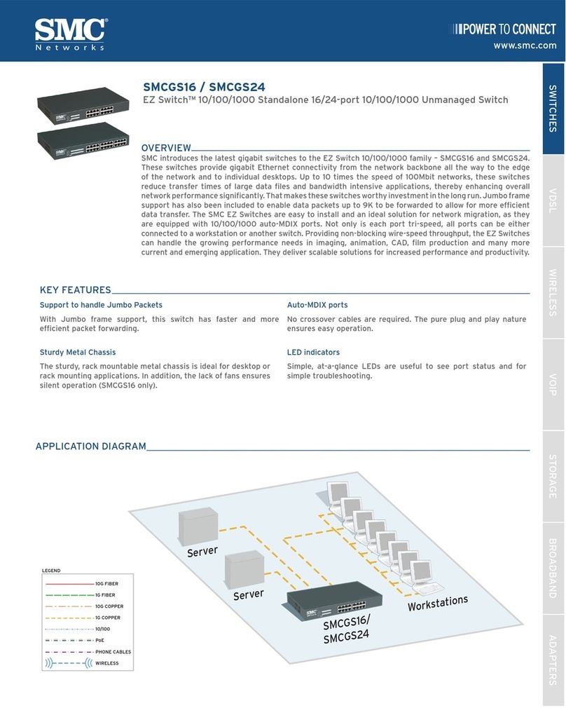
SMC Networks EZ Switch SMCGS16-Smart User manual

SMC Networks

SMC Networks EZ Switch SMCGS16-Smart User manual

SMC Networks 6724L2 Programming manual

SMC Networks

SMC Networks 6724L2 Programming manual

SMC Networks TigerSwitch SMC8728L2 User manual

SMC Networks

SMC Networks TigerSwitch SMC8728L2 User manual

SMC Networks D-F6# Series User manual

SMC Networks

SMC Networks D-F6# Series User manual

SMC Networks TigerStack User manual

SMC Networks

SMC Networks TigerStack User manual

SMC Networks TigerSwitch 10/100 SMC6750L2 User manual

SMC Networks

SMC Networks TigerSwitch 10/100 SMC6750L2 User manual

SMC Networks SMC8612XL3 F 1.0.1.3 User manual

SMC Networks

SMC Networks SMC8612XL3 F 1.0.1.3 User manual

SMC Networks SMC EZ Stack 10/100 SMC5216 User manual

SMC Networks

SMC Networks SMC EZ Stack 10/100 SMC5216 User manual

SMC Networks SMC8126L2 Programming manual

SMC Networks

SMC Networks SMC8126L2 Programming manual

SMC Networks 8506T User manual

SMC Networks

SMC Networks 8506T User manual

SMC Networks PF2W7 Series User manual

SMC Networks

SMC Networks PF2W7 Series User manual

SMC Networks 6750L2 User manual

SMC Networks

SMC Networks 6750L2 User manual

SMC Networks TigerSwitch SMC8648T User manual

SMC Networks

SMC Networks TigerSwitch SMC8648T User manual

SMC Networks ISE35 User manual

SMC Networks

SMC Networks ISE35 User manual

Popular Switch manuals by other brands

Aeotec ZWA003-S operating manual

Aeotec

Aeotec ZWA003-S operating manual

TRENDnet TK-209i Quick installation guide

TRENDnet

TRENDnet TK-209i Quick installation guide

Planet FGSW-2022VHP user manual

Planet

Planet FGSW-2022VHP user manual

Avocent AutoView 2000  AV2000BC AV2000BC Installer/user guide

Avocent

Avocent AutoView 2000 AV2000BC AV2000BC Installer/user guide

Moxa Technologies PT-7728 Series user manual

Moxa Technologies

Moxa Technologies PT-7728 Series user manual

Intos Electronic inLine 35392I operating instructions

Intos Electronic

Intos Electronic inLine 35392I operating instructions

Cisco Catalyst 3560-X-24T Technical specifications

Cisco

Cisco Catalyst 3560-X-24T Technical specifications

Asante IntraCore IC3648 Specifications

Asante

Asante IntraCore IC3648 Specifications

Siemens SIRIUS 3SE7310-1AE Series Original operating instructions

Siemens

Siemens SIRIUS 3SE7310-1AE Series Original operating instructions

Edge-Core DCS520 quick start guide

Edge-Core

Edge-Core DCS520 quick start guide

RGBLE S00203 user manual

RGBLE

RGBLE S00203 user manual

Thrustmaster FLIGHT SIMULATOR X quick guide

Thrustmaster

Thrustmaster FLIGHT SIMULATOR X quick guide

Southwire SURGE GUARD 41390 RVC troubleshooting guide

Southwire

Southwire SURGE GUARD 41390 RVC troubleshooting guide

Buhler Nivotemp NT 61 Brief instructions

Buhler

Buhler Nivotemp NT 61 Brief instructions

Kramer VS-41HDCP user manual

Kramer

Kramer VS-41HDCP user manual

Techly IDATA AU-270 user manual

Techly

Techly IDATA AU-270 user manual

Belkin F1U109 user manual

Belkin

Belkin F1U109 user manual

Emerson Rosemount 2521 Series quick start guide

Emerson

Emerson Rosemount 2521 Series quick start guide

manuals.online logo
manuals.online logoBrands
  • About & Mission
  • Contact us
  • Privacy Policy
  • Terms and Conditions

Copyright 2025 Manuals.Online. All Rights Reserved.

PS1000-TF2Z054EN
Page 1 of 2
Instruction Manual
Air Checker: Electronic Pressure Switch
PS1000 / PS1100 / PS1200
The intended use of the compact pressure switch is to measure, monitor
and display pressure and provide an output signal.
1 Safety Instructions
These safety instructions are intended to prevent hazardous situations
and/or equipment damage. These instructions indicate the level of
potential hazard with the labels of “Caution,” “Warning” or “Danger.”
They are all important notes for safety and must be followed in addition
to International Standards (ISO/IEC)*1), and other safety regulations.
*1) ISO 4414: Pneumatic fluid power - General rules relating to systems.
ISO 4413: Hydraulic fluid power - General rules relating to systems.
IEC 60204-1: Safety of machinery - Electrical equipment of machines.
(Part 1: General requirements)
ISO 10218-1: Robots and robotic devices - Safety requirements for
industrial robots - Part 1: Robots.
•Refer to product catalogue, Operation Manual and Handling
Precautions for SMC Products for additional information.
•Keep this manual in a safe place for future reference.
Caution
Caution indicates a hazard with a low level of risk which, if
not avoided, could result in minor or moderate injury.
Warning
Warning indicates a hazard with a medium level of risk
which, if not avoided, could result in death or serious injury.
Danger
Danger indicates a hazard with a high level of risk which, if
not avoided, will result in death or serious injury.
Warning
•Always ensure compliance with relevant safety laws and
standards.
•All work must be carried out in a safe manner by a qualified person in
compliance with applicable national regulations.
•This product is class A equipment intended for use in an industrial
environment. There may be potential difficulties in ensuring
electromagnetic compatibility in other environments due to conducted
or radiated disturbances.
•Refer to the operation manual or catalogue on the SMC website (URL:
https://www.smcworld.com) for more safety instructions.
2 Specifications
2.1 General specifications
2.2 PS1000 / PS1100 switch specification
2.3 PS1200 switch specification
3 Installation
3.1 Installation Warning
Do not install the product unless the safety instructions have been read
and understood.
3.2 Piping
Caution
•Before connecting piping make sure to clean up chips, cutting oil, dust
etc.
3.3 Environment Warning
•Do not use in an environment where corrosive gases, chemicals, salt
water or steam are present.
•Do not use in an explosive atmosphere.
•Do not expose to direct sunlight. Use a suitable protective cover.
•Do not install in a location subject to vibration or impact. Check the
product specifications.
•Do not mount in a location exposed to radiant heat.
3.4 Lubrication Caution
•SMC products have been lubricated for life at manufacture, and do not
require lubrication in service.
•If a lubricant is used in the system, use turbine oil Class 1 (no additive),
ISO VG32. Once lubricant is used in the system, lubrication must be
continued because the original lubricant applied during manufacturing
will be washed away.
4 Wiring
4.1 Wiring
•Connections should be made with the power supply turned OFF.
•Use a separate route for the product wiring and any power or high
voltage wiring. Otherwise, malfunction may result due to noise.
•Incorrect wiring may cause damage to the pressure switch, breakdown
and malfunction. Confirm the colour of the wires with the operation
manual before wiring.
•Wiring applying repeated bending and tensile stress to the lead wire
can break the circuit.
•The recommended bend radius of the lead wire is 6 times the outside
diameter of the sheath, or 33 times the outside diameter of the
insulation material, whichever is larger.
•Avoid defective insulation (crossed lines with other circuit, ground fault,
defective insulation between terminals, etc.) with the wiring.
Excessive current can flow through the pressure switch, which may
cause damage.
•If the pressure switch is turned on with no load connected to the switch,
over current will flow, causing the pressure switch to break instantly.
•The pressure switch has no reverse connection protection for the
brown (+) and blue (-) of the power supply line.
•Do not exceed the maximum allowable load (24 VDC,40mA) specified.
4.2 Circuit Diagram
4 Wiring (continued)
4.3 Wiring diagram
Example of connection to a PLC (sequence controller).
(Source Input type)
(Sink Input type)
5 Setting
•Adjust the calibration adjustment to set the ON pressure.
•Rotate clockwise to increase the set pressure. For setting vacuum
pressure rotate anticlockwise.
•For setting, use a flat blade screwdriver suitable for a trimmer. Rotate
lightly to adjust.
•The rotation angle of the trimmer is 220°.
There is a stop provided to prevent the trimmer from rotating beyond
its limits. Rotation beyond the limits can damage the trimmer. Adjust
the trimmer gently within the rotation angle.
Caution
•Do not use a large screwdriver as this may damage the trimmer groove.
•Gently turn the trimmer and do not exceed the trimmer adjustment
range.
5.1 Hysteresis
Hysteresis is the pressure difference between the ON and OFF pressure.
The set pressure is the pressure selected to switch from OFF to ON.
6 How to Order
Refer to the operation manual or catalogue on the SMC website (URL:
https://www.smcworld.com) for How to order information.
ORIGINAL INSTRUCTIONS
Model No. PS1000 PS1100 PS1200
Switch output
Pressure ≥
Set pressure:
ON
Pressure ≤ Set pressure: ON
Max. operating
pressure
1 MPa 500 kPa
Setting pressure
range
-0.1 to 0.45
MPa
-0.1 to 0.4
MPa
-100 to 0
kPa
Applicable fluids Air, non-corrosive gas, non-flammable gas
Indicator light Switch ON: Red LED turns ON
Temp.
characteristics
±3% F.S.
Repeatability ±1% F.S.
Hysteresis 4% F.S. or less
10% F.S.
or less
Load voltage
12 to 24 VDC ±10%,
ripple (p-p) 10% or less
Load current 5 to 40 mA
Leakage current 1 mA max.
Internal voltage drop 5 V max.
Operating
temperature range
0 to 60°C (no condensation)
Insulation resistance
2 MΩ or more at 500 VDC
(between live parts and case)
Withstand voltage
1000 VAC, 1 minute
(between live parts and case)
Port sizes R06 φ6 reducer
R07 φ1/4” reducer
Weight 5 g (excluding lead wire)
Enclosure rating IP40
Lead wire
Oil resistant vinyl cabtyre cable
2 cores, φ2.55, 3 m long
Conductor cross section 0.18 mm2
Insulator O.D. 0.96 mm
Material of wetted
parts
Sensor: Silicon, Body: PBT, O-ring: HNBR
The switch turns ON when
the set pressure is reached
or exceeded.
The switch turns ON at the
set pressure or below.
Set pressure
Set pressure
The switch turns ON
at the set pressure or

below.
High
vacuum
High
pressure
Pressure
setting trimmer
Setting
pressure
Atmospheric
pressure
PS1000-TF2Z054EN
Page 2 of 2
7 Outline Dimensions
Refer to the operation manual or catalogue on the SMC website (URL:
https://www.smcworld.com) for Outline Dimensions.
8 Maintenance
8.1 General Maintenance Caution
•Not following proper maintenance procedures could cause the product
to malfunction and lead to equipment damage.
•If handled improperly, compressed air can be dangerous.
•Maintenance of pneumatic systems should be performed only by
qualified personnel.
•Before performing maintenance, turn off the power supply and be sure
to cut off the supply pressure. Confirm that the air is released to
atmosphere.
•After installation and maintenance, apply operating pressure and
power to the equipment and perform appropriate functional and
leakage tests to make sure the equipment is installed correctly.
•If any electrical connections are disturbed during maintenance, ensure
they are reconnected correctly and safety checks are carried out as
required to ensure continued compliance with applicable national
regulations.
•Do not make any modification to the product.
•Do not disassemble the product, unless required by installation or
maintenance instructions.
•Perform regular maintenance and inspections.
It may not be impossible to guarantee safety due to unexpected
malfunction or erroneous operation. Perform regular inspections and
confirm normal operation.
•Use a soft cloth to clean the pressure switch. For heavy stains, use a
cloth soaked with diluted neutral detergent and fully squeezed, then
wipe up the stains again with a dry cloth.
9 Limitations of Use
9.1 Limited warranty and Disclaimer/Compliance Requirements
Refer to Handling Precautions for SMC Products.
Caution
•SMC products are not intended for use as instruments for legal
metrology.
Measurement instruments that SMC manufactures or sells have not
been qualified by type approval tests relevant to the metrology
(measurement) laws of each country.
Therefore, SMC products cannot be used for business or certification
ordained by the metrology (measurement) laws of each country.
10 Product disposal
This product shall not be disposed of as municipal waste. Check your
local regulations and guidelines to dispose of this product correctly, in
order to reduce the impact on human health and the environment.
11 Contacts
Refer to www.smcworld.com or www.smc.eu for your local distributor /
importer.
URL: https://www.smcworld.com (Global) https://www.smc.eu (Europe)
SMC Corporation, 4-14-1, Sotokanda, Chiyoda-ku, Tokyo 101-0021, Japan
Specifications are subject to change without prior notice from the manufacturer.
© 2021 SMC Corporation All Rights Reserved.
Template DKP50047-F-085M