•Night-Time Relative Humidity Setpoint (display e %)
•Relative Humidity Hysteresis (display % e h)
•Sprinkling Time (display rt))
•Maximum Sprinkling Time (display to)
Display and use of the humidity control requires the connection of a combined sensor available as an
accessory.
This registers both humidity and air temperature. This can be used to control an additional heater via
Socket 2.
If the maximum sprinkling time is exceeded to also appears in the display.
The sprinkling is stopped for 5 hours; the error display is then in reset and control mode for humidity
restarts.
The time monitoring can be switched off, e.g. for operation with nebulisers. To this end, the value for to
must be set to 0. If the value selected for rt is larger than 0, sprinkling occurs (activation with Socket 3) for
the set time and a subsequent pause for 30 seconds. This occurs for safety reasons to register the effect of
the sprinkling and to avoid excessive humidification. If this pause is not wanted, rt can be set to 0. The
activation (sprinkling) then continues until the set humidity setpoint is reached.
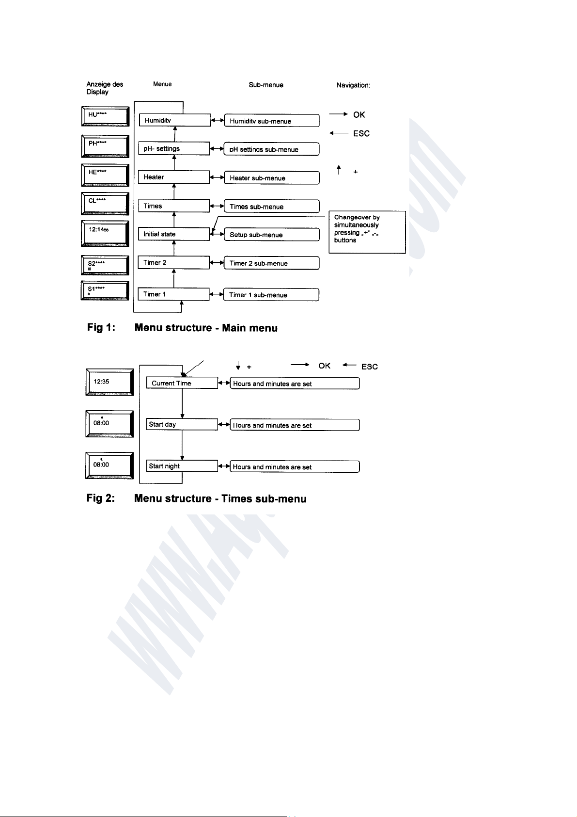
7.5 Socket 2 Timer settings
From the HUMIDITY SETTINGS menu, press the + BUTTON to switch to the SOCKET 2 SWITCH
SETTINGS menu (see also Fig. 6).
This menu only appears if Socket 2 was configured for switching times (ti) in the SETUP sub-menu.
S1 is displayed.
Confirming this selection with the OK BUTTON leads to the SOCKET 2 sub-menu.
Make the settings as described above. If you want to skip an input, use the + BUTTON to switch to the next
selection item or the ESC BUTTON to switch to the main menu.
The following inputs are possible:
•Switching time 1 ON (display II, ON and 4)
•Switching time 1 OFF (display II, OFF and 1)
•Switching time 2 ON (display II, ON and 2)
•Switching time 2 OFF (display II, OFF and 2)
•Switching time 3 ON (display II, ON and 3)
•Switching time 3 OFF (display II, OFF and 3)
•Switching time 4 ON (display II, ON and 4)
•Switching time 4 OFF (display II, OFF and 4)
Up to four switching times can be defined.
No switching takes place if the ON and OFF switching times are identical.
7.6 Socket 3 Timer settings
From the SOCKET 2 SWITCH SETTINGS menu, press the + BUTTON to switch to the SOCKET 3
SWITCH SETTINGS menu (see also Fig. 7 for aquarium mode and Fig. 8 for terrarium mode.). This menu
only appears if Socket 3 was configured for switching times () in the SETUP sub-menu.
is displayed.
Confirming this selection with the OK BUTTON leads to the SOCKET 3 sub-menu.
Make the settings as described above. If you want to skip an input, use the + BUTTON to switch to the next
selection item or the ESC BUTTON to switch to the main menu.
The inputs differ as follows depending on the operating mode selected:
Aquarium mode Terrarium mode
• Switchin
time 1 ON • Switchin
time 1 ON
• Switchin
time 1 OFF • Switchin
time 1 DURATION
• Switchin
time 2 ON • Switchin
time 2 ON