SME AC-M1 User manual

AC-M1
AC-M1
PRELIMINARY VERSION

Table of Contents
1 Introduction.....................................................................................................................4
1.1 About SME Company................................................................................................4
1.2 About this manual......................................................................................................4
1.3 About warning, caution and information notices........................................................4
1.4 Product warranty informations...................................................................................4
1.5 How to find us...........................................................................................................5
2 AC_SmartMotion AC-M1 Overview................................................................................6
2.1 Product Description...................................................................................................6
2.2 General Technical Specifications..............................................................................7
2.3 Packaging configuration............................................................................................8
2.4 Product indication labels.........................................................................................10
3 Installation and wiring...................................................................................................11
3.1 General description.................................................................................................11
3.2 Mounting the controller............................................................................................11
3.3 Cooling requirements..............................................................................................12
3.3.1 AC-M1 with Heat Sink.....................................................................................12
3.3.2 AC-M1 with Aluminium Baseplate...................................................................12
3.3.3 Clearances......................................................................................................12
..................................................................................................................................13
3.4 List of complete pin-out...........................................................................................14
3.4.1 AC-M1 pin-out for PUMP application.............................................................14
3.4.2 AC-M1 pin-out for DRIVE application............................................................17
3.4.3 Connector Parts..............................................................................................19
3.5 Typical connection diagrams...................................................................................20
3.5.1 General electrical vehicle................................................................................20
3.5.2 Pump motor application in a twin drive system...............................................20
3.5.3 Screw torque for the power connections.........................................................20
3.6 External devices description....................................................................................23
3.6.1 Encoder...........................................................................................................23
3.6.2 COMPACT Display..........................................................................................24
3.7 Programmable parameters......................................................................................25
3.8 Initial set-up.............................................................................................................25
3.9 Technical specifications ..........................................................................................25
4 Main function management..........................................................................................29
4.1 Static return to off....................................................................................................29
4.2 Buzzer management...............................................................................................29
4.3 BDI measure management.....................................................................................29
5 User interfaces..............................................................................................................30
5.1 Introduction.............................................................................................................30
5.2 EyePlus software....................................................................................................30
PRELIMINARY VERSION 2

5.2.1 Overview.........................................................................................................30
5.2.2 Serial interconnection cable............................................................................31
5.2.3 System requirements......................................................................................31
5.3 COMPACT Display..................................................................................................33
5.3.1 Overview.........................................................................................................33
5.3.2 General characteristics ..................................................................................33
5.3.3 Connections....................................................................................................34
5.3.4 Mechanical drawings.......................................................................................34
6 Diagnostic and troubleshooting..................................................................................37
6.1 Overview.................................................................................................................37
6.2 Alarm list and description........................................................................................38
7 EMC Suggestions..........................................................................................................47
7.1 General overview on EMC......................................................................................47
7.2 EM emissions..........................................................................................................47
7.3 Immunity to EM disturbances..................................................................................47
8 Maintenance...................................................................................................................49
8.1 Spare part list..........................................................................................................49
9 Appendix A. General technical overview of SME technology...................................50
9.1 History of AC induction motors and AC controllers..................................................50
9.2 Technical advantages of AC induction motors.........................................................50
9.3 AC motor general description and principles of operation .....................................51
9.3.1 General description of an AC motor................................................................51
9.3.2 Principle of operation .....................................................................................51
9.3.3 Electrical model...............................................................................................53
9.4 ITC vector drive system ..........................................................................................54
9.4.1 Basic operation of ITC vector drive system.....................................................54
9.4.2 Main ITC components.....................................................................................56
9.4.3 Basic ITC functions.........................................................................................56
9.4.4 ITC characteristics..........................................................................................57
10 Appendix B: Programmable parameters...................................................................58
PRELIMINARY VERSION 3

1 Introduction
1.1 About SME Company
SME group, founded in 1974, is a high technology company, manufacturer of electronic
controllers and related products for application in battery powered vehicles, particularly
forklift trucks and specialized in the development of AC power controllers.
The group provides intelligent and innovative solutions to satisfy market requirements,
achieving worldwide customer satisfaction.
SME group is able to offer a complete motion system for the different industrial lift truck
ranges guaranteeing a high and safe performance customized to the client's requirements.
1.2 About this manual
This manual presents important information on configuring lift and drive systems using the
AC_SmartMotion AC-M1 as well as details on sizing and selecting system components,
options and accessories in an electrically powered vehicle utilizing CAN Bus (CAN Open
protocol) for communications and control.
This manual also presents an overview of AC induction motor and AC drives technology.
This version replaces all previous existing versions of the manual, if any.
1.3 About warning, caution and information notices
Special attention must be paid to the information presented in Warning, Caution and other
kinds of information notices when they appear in this manual.
Failure to follow those recommendations may result in dangerous situations or in damages
to the components, for which SME will not respond.
Warnings. A Warning informs the user of a hazard or a potential hazard
which could result in serious or fatal injury if the precautions or
instructions given in the warning notice are not observed.
Cautions. A caution informs the reader of a hazard or a potential
hazard which could result in a serious damage to the appliance.
Information notices. An information notice contains additional, not
essential pieces of information to complete or to clarify the meaning of
the paragraph they are placed into.
1.4 Product warranty informations
SME offers a two-year warranty on all the products, unless a different agreement has been
put in place. Refer to the sales agreement or contract under which the AC_SmartMotion
was purchased for a complete statement of the product warranty.
PRELIMINARY VERSION 4

1.5 How to find us
All the World Regions (except Asia):
●
For any information on commercial and technical issues, please contact either your
dealer or directly SME Headquarter at the following address:
SME S.p.A.
Via della Tecnica, n°40
36071 Arzignano (VI) - ITALY
Tel: +39 0444 470511
Fax: +39 0444 451803
Email: [email protected]
Asia Region:
●
For any information on commercial and technical issues, please contact either your
dealer or SME Shanghai headquarters at the following address:
SME (SHANGHAI) CO. LTD
1288, Zhangxiang Road
20180 Anting Town
Jiading District
Shanghai - PEOPLE'S REPUBLIC OF CHINA
Tel: +86 (0)21 59501530
Fax: +86 (0)21 59501502
PRELIMINARY VERSION 5

2 AC_SmartMotion AC-M1 Overview
2.1 Product Description
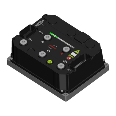
The AC-M1 Controller is designed to control AC motors up to 10kW.
Being based on high reliable DCB technology and exceptionally stable ITC Control
Algorithm, AC-M1 Controller is a revolutionary and high quality solution for medium power
applications.
AC-M1 Controller can be easily connected to other peripherals to perform a complex
network in which all nodes can communicate with the others via CAN bus.
When used in pump configuration, it can be connected to an AC-M2 controller customized
for twin drive motors applications.
The product is suitable for the following range of applications: Counterbalanced Lift Trucks,
Cleaning Machines, Golf cars, Aerial Lifts, Tractors, Utility Vehicles, Tow Trucks.
PRELIMINARY VERSION 6

2.2 General Technical Specifications
AC-M1 has the following remarkable features:
✔
Low R
DS,on
MOSFET
✔
16 bits DSP controlling 1 AC motor
✔
High Speed FLASH Memory
✔
Switching Frequency: 9kHz
✔
Integrated Hall Effect Current Sensors
✔
Communication: RS232, LIN and CAN-Bus
✔
Available Supply Voltages (Volts): 24,36,48,72,80
✔
Maximum Current, measured in a two-minute time interval.
○
24V version: 350-450-600 A
rms
○
36/48V version: 375-500 A
rms
○
80V version: 350-450 A
rms
✔
Working temperature range: -30°C/+40°C
✔
Maximum heat sink temperature: 100°C
✔
Mechanical Characteristics:
○
Dimensions: 210x145x91 mm
○
Connectors: 2x23 Ampseal terminals
○
Environmental Protection: IP65
○
Available with Aluminum baseplate or finned Heatsink
✔
I/O specifications:
○
N°21 Digital Inputs
○
N°8 Analogue Inputs
○
N°5 Outputs
PRELIMINARY VERSION 7

The following model charts provide further details on the product family:
Model Chart for 24V version
Model Name AC Inverter Max Arms(2’) Max Power (2’)
AC-M1 24V 350A 350A
rms
9.7 kVA
AC-M1 24V 450A 450 A
rms
12.5 kVA
AC-M1 24V 600A 600 A
rms
16.6 kVA
Model Chart for 36/48V version
Model Name AC Inverter Max Arms(2’) Max Power (2’)
AC-M1 36/48V 375A 375 A
rms
20.8 kVA
AC-M1 36/48V 500A 500 A
rms
27.5 kVA
Model Chart for 72/80V version
Model Name AC Inverter Max Arms(2’) Max Power (2’)
AC-M1 72/80V 350A 350A
rms
32.3 kVA
AC-M1 72/80V 450A 450 A
rms
41.6 kVA
2.3 Packaging configuration
AC-M1 is available in one of the following packages:
1. with an Aluminum baseplate, or
2. with a heat sink, which uses the convection and therefore requires a fan.
PRELIMINARY VERSION 8

Figure 1: AC-M1 . All the dimensions are in millimetres.
PRELIMINARY VERSION 9

2.4 Product indication labels
The product label shows important data regarding the specific product.
The product label is placed in the same position for all the versions of AC-M1 (see fig. 1).
The meaning of each field is described in the table below.
Field Description
Type Code It is the code that SME assigns to the specific family of
products.
Product Code It is the code that SME assigns to the specific customer.
Rating Data It can contain the indication of the input voltages and the output
currents supplied by the product.
Production Number It is the production lot number.
Customer Code It is the customer's internal reference to the application to which
AC-M1 is applied.
PRELIMINARY VERSION 10

3 Installation and wiring
3.1 General description
The AC-M1 is composed by a control section and a power section, both enclosed in a
plastic cover with an aluminium baseplate or a heat sink on the bottom of the enclosure.
There is a power module which can be connected to a three-phase AC motor through the
power outputs labelled as U, V, W. There can be an optional output (labelled as P) for a
DC pump motor.
Two 23 ways ampseal connectors ( named K1and K2), permits to interface control board
to lift truck electrical/electronic sub-devices. See tables on pages 14 and followings for the
complete pin-out of this connector.
There are two connectors +B and -B which supply the power module.
Please see figure 1 on page 9 for AC-M1 drawing.
SME recommends you to protect the AC-M1 against reversed battery
polarity.
3.2 Mounting the controller
AC-M1 can be oriented in any direction and meets IP65 environmental protection rating.
However, the location should be carefully chosen to keep the controller clean and dry.
If a clean, dry mounting location cannot be found, a cover should be used to shield the
controller from water and contaminants.
The outline and mounting hole dimensions for the AC-M1 controller are shown in figures
Errore: sorgente del riferimento non trovata and 1 on page 9.
To ensure full rated power, the controller should be fastened to a clean, flat metal surface
with four 6.5 mm diameter bolts, using the holes provided.
A thermal joint compound must be used to improve heat conduction from the controller
heatsink to the mounting surface.
During the design and development of your end product, you will need to ensure that its
EMC performance complies with applicable regulations.
The AC-M1 controller contains ESD-sensitive components. Use
appropriate precautions in connecting, disconnecting, and handling the
controller.
For EMC and ESD purposes, SME strongly recommends that both the
AC-M1 heat sink and the houses of the motors are connected to the
chassis of the truck.
PRELIMINARY VERSION 11

Working on electrical systems is potentially dangerous; you should
protect yourself against :
Uncontrolled operation: some conditions could cause the motor to run
out of control: disconnect the motor or jack up the vehicle and get the
drive wheels off the ground before attempting any work on the motor
control circuitry.
Voltage hazard and high current arcs: batteries can supply high
voltage and very high power, and arcs can occur if they are short
circuited. Always disconnect the battery circuit before working on the
motor control circuit.
Wear safety glasses and use properly insulated tools to prevent shorts.
Lead acid batteries: charging or discharging generates hydrogen gas,
which can build up and go around the batteries. Follow the battery
manufacturer’s safety recommendations and wear safety glasses.
3.3 Cooling requirements
3.3.1 AC-M1 with Heat Sink
A massive heat sink comprising the entire bottom surface of the AC-M1 transfers heat out
of the power conversion section to the surrounding air.
Drives operating at or near continuous power output require forced air cooling to maintain
heat sink temperature in the safe operating zone.
We recommend ambient temperature air to be directed over the heat sink fins to maintain
heat sink temperature below 85 °C.
Either an axial blower or two small muffin fans can provide the necessary airflow.
3.3.2 AC-M1 with Aluminium Baseplate
A massive heat sink comprising the entire bottom surface of the AC-M1 transfers heat out
of the power conversion section to the vehicle body.
Drives operating at or near their continuous power output require different thermal
resistance depending on AC-M1 size for dissipation of heat to maintain heat sink
temperature in the safe operating zone.
In this case, AC-M1 is cooled by the surface contact to the vehicle body, so it is important
to pay much attention to the flatness and the roughness of the surface of the vehicle frame
where AC-M1 is mounted.
Apply thermal grease to the AC-M1 before mounting for better cooling effect.
You should keep the planarity of the surface under 0.5mm, as shown in Figure 2.
3.3.3 Clearances
For all AC-M1 models 50 mm clearances in front of and behind the AC-M1 are required for
airflow; 50 mm clearance above the AC-M1 is required for installation/removal of interface
connectors and wiring. Refer to figures 1 on pages 9 for the dimensions of AC-M1.
PRELIMINARY VERSION 12

Figure 2: Planarity specifications for the AC-M1with aluminium baseplate.
PRELIMINARY VERSION 13

3.4 List of complete pin-out
3.4.1 AC-M1 pin-out for PUMP application
K1 connector pin-out for AC-M1 : PUMP application
Pin Name I/O Specification Function
1 +KEY (B) Supply
input
Rated battery +25/-30%,
6Amax
Positive supply of the control
section of the AC-M1
2digital
input
4mA pull-up,
VL<=1V,
VH>=3,5V
Reserve
3digital
input
4mA pull-up,
VL<=1V,
VH>=3,5V
Reserve
4digital
input
4mA pull-up,
VL<=1V,
VH>=3,5V
Reserve
5digital
input
4mA pull-up,
VL<=1V,
VH>=3,5V
Reserve
6 TILT digital
input
4mA pull-up,
VL<=1V,
VH>=3,5V
Tilt request
7 SIDE SHIFT digital
input
4mA pull-up,
VL<=1V,
VH>=3,5V
Side shift request
8 BUZZER output Low side 0,5A Buzzer command
9 COMMON Positive
output High side 5A max Positive common
10 RX Input Diagnosis interface
11 TX Out Diagnosis interface
12 digital
input
4mA pull-up,
VL<=1V,
VH>=3,5V
Reserve
13 digital
input
4mA pull-up,
VL<=1V,
VH>=3,5V
Reserve
14 LIN I/O 12mA pull-up LIN display connection or LED
diagnosis
15 CAN-H I/O CAN-bus H line input for CAN (No internal
PRELIMINARY VERSION 14

K1 connector pin-out for AC-M1 : PUMP application
Pin Name I/O Specification Function
termination resistor)
16 output Low side 2A Reserve command
17 output Low side 1,5A Reserve command
18 GND Negative logic supply
19 FAN output Low side 1,5A FAN command
20 OUT1 output Low side 1,5A Reserve command
21 +12V auxiliary
supply 12V 300mAmax 12V supply
22 GND CAN CAN- bus negative supply
23 CAN-L I/O CAN-bus L line input for CAN (No internal
termination resistor)
K2 connector pin-out for AC-M1 : PUMP application
Pin Name I/O Specification Function
1 +5E auxiliary
supply
5V+/-5%
200mAmax 5V supply
2digital
input
20mA pull-up,
VL<=1V,
VH>=3,5V
Reserve
3digital
input
20mA pull-up,
VL<=1V,
VH>=3,5V
Reserve
4 ENC.B1 digital
input
20mA pull-up,
VL<=1V,
VH>=3,5V
Phase B signal of the sensor
bearing mounted in the AC
pump motor.
5 ENC.A1 digital
input
20mA pull-up,
VL<=1V,
VH>=3,5V
Phase A signal of the sensor
bearing mounted in the AC
pump motor.
6digital
input
4mA pull-up,
VL<=1V,
VH>=3,5V
Reserve
7digital
input
4mA pull-up,
VL<=1V,
VH>=3,5V
Reserve
8 LIFT digital
input
4mA pull-up,
VL<=1V,
VH>=3,5V
Max LIFT speed request
PRELIMINARY VERSION 15

K2 connector pin-out for AC-M1 : PUMP application
Pin Name I/O Specification Function
9 GND ENC Negative logic supply
10 analogue
input Pull-up Reserve
11 T. MOTOR 1 analogue
input Pull-up Analogue input for pump motor
thermal sensor
12 digital
input
4mA pull-up,
VL<=1V,
VH>=3,5V
Reserve
13 LIFT PRESSURE analogue
input 0/12V pull-down Lift pressure sensor
14 AUX 1 digital
input
4mA pull-up,
VL<=1V,
VH>=3,5V
Aux1 request
15 AUX2 digital
input
4mA pull-up,
VL<=1V,
VH>=3,5V
Aux2 request
16 digital
input
4mA pull-up,
VL<=1V,
VH>=3,5V
Reserve
17 LIMITATION 1 digital
input
4mA pull-up,
VL<=1V,
VH>=3,5V
Limitation speed 1
18 digital
input
4mA pull-up,
VL<=1V,
VH>=3,5V
Reserve
19 analogue
input 0/12V pull-down Reserve
20 analogue
input 0/12V pull-down Reserve
21 analogue
input 0/12V pull-down Reserve
22 LIFT LEVER analogue
input 0/12V pull-down Lift speed request
23 LIMITATION 2 digital
input
pull-down,
max input: 24V 4mA,
VL<=1V,
VH>=3,5V
Limitation speed 2
PRELIMINARY VERSION 16

3.4.2 AC-M1 pin-out for DRIVE application
K1 connector pin-out for AC-M1 : DRIVE application
Pin Name I/O Specification Function
1 +KEY (B) Supply
input
Rated battery +25/-30%,
6Amax
Positive supply of the control
section of the AC-M1
2 SEAT digital
input
4mA pull-up,
VL<=1V,
VH>=3,5V
Safety contact signal; the safety
contact should be normally
open.
3 REVERSE digital
input
4mA pull-up,
VL<=1V,
VH>=3,5V
Reverse direction selection
4FORWARD
digital
input
4mA pull-up,
VL<=1V,
VH>=3,5V
Forward direction selection
5 START digital
input
4mA pull-up,
VL<=1V,
VH>=3,5V
Throttle start selection
6digital
input
4mA pull-up,
VL<=1V,
VH>=3,5V
Reserve
7digital
input
4mA pull-up,
VL<=1V,
VH>=3,5V
Reserve
8 BUZZER output Low side 0,5A Buzzer command
9 COMMON Positive
output High side 5A max Positive common
10 RX Input Diagnosis interface
11 TX Out Diagnosis interface
12 PEDAL BRAKE digital
input
4mA pull-up,
VL<=1V,
VH>=3,5V
Pedal brake request
13 PARK BRAKE digital
input
4mA pull-up,
VL<=1V,
VH>=3,5V
Park brake request
14 LIN I/O 12mA pull-up LIN display connection or LED
diagnosis
15 CAN-H I/O CAN-bus H line input for CAN (No internal
termination resistor)
16 OUT3 output Low side 2A NEGATIVE BRAKE command
17 MAIN output Low side 1,5A Main contactor command
PRELIMINARY VERSION 17

K1 connector pin-out for AC-M1 : DRIVE application
Pin Name I/O Specification Function
18 GND Negative logic supply
19 FAN output Low side 1,5A FAN command
20 OUT1 output Low side 1,5A Reserve command
21 +12V auxiliary
supply 12V 300mAmax 12V supply
22 GND CAN CAN- bus negative supply
23 CAN-L I/O CAN-bus L line input for CAN (No internal
termination resistor)
K2 connector pin-out for AC-M1 : DRIVE application
Pin Name I/O Specification Function
1 +5E auxiliary
supply
5V+/-5%
200mAmax 5V supply
2digital
input
20mA pull-up,
VL<=1V,
VH>=3,5V
Reserve
3digital
input
20mA pull-up,
VL<=1V,
VH>=3,5V
Reserve
4 ENC.B1 digital
input
20mA pull-up,
VL<=1V,
VH>=3,5V
Phase B signal of the sensor
bearing mounted in the AC
right drive motor.
5 ENC.A1 digital
input
20mA pull-up,
VL<=1V,
VH>=3,5V
Phase A signal of the sensor
bearing mounted in the AC
right drive motor.
6digital
input
4mA pull-up,
VL<=1V,
VH>=3,5V
Reserve
7digital
input
4mA pull-up,
VL<=1V,
VH>=3,5V
Reserve
8digital
input
4mA pull-up,
VL<=1V,
VH>=3,5V
Reserve
9 GND ENC Negative logic supply
10 analogue
input Pull-up Reserve
PRELIMINARY VERSION 18

K2 connector pin-out for AC-M1 : DRIVE application
Pin Name I/O Specification Function
11 T. MOTOR analogue
input Pull-up Analogue input for drive motor
thermal sensor
12 digital
input
4mA pull-up,
VL<=1V,
VH>=3,5V
Reserve
13 analogue
input 0/12V pull-down Reserve
14 digital
input
4mA pull-up,
VL<=1V,
VH>=3,5V
Reserve
15 digital
input
4mA pull-up,
VL<=1V,
VH>=3,5V
Reserve
16 digital
input
4mA pull-up,
VL<=1V,
VH>=3,5V
Reserve
17 digital
input
pull-down,
max input: 24V 4mA,
VL<=1V,
VH>=3,5V
Reserve
18 digital
input
4mA pull-up,
VL<=1V,
VH>=3,5V
Reserve
19 PEDAL BRAKE
SENSOR
analogue
input 0/12V pull-down Brake pressure sensor
20 STEERING analogue
input 0/12V pull-down Steering angle sensor
21 ACCELERATOR analogue
input 0/12V pull-down Throttle pedal
22 analogue
input 0/12V pull-down Reserve
23 digital
input
pull-down,
max input: 24V 4mA,
VL<=1V,
VH>=3,5V
Reserve
3.4.3 Connector Parts
The K1 and K2 connectors are AMPSEAL 23 Pins, manufactured by AMP.
The external plug assembly is AMP cod. 770680-1, with contact 0,5-1,4mm2 cod. 770854-1.
PRELIMINARY VERSION 19

3.5 Typical connection diagrams
3.5.1 General electrical vehicle
Figure 3 shows a connection diagram of a general electrical vehicle using the AC-M1 as
control board and traction motor drive. Pump motor is not present.
3.5.2 Pump motor application in a twin drive system
Figure 4 shows a typical connection diagram showing AC-M1 control powering an A.C.
pump motor in a twin drive motors system.
3.5.3 Screw torque for the power connections.
The recommended screw torque for fixing the connections +B, -B, U,V and W is 6 Nm.
This value is reported on the label placed on the cover: exceeding the recommended
value may cause damages.
PRELIMINARY VERSION 20
Other manuals for AC-M1
1
Table of contents
Other SME Controllers manuals
Popular Controllers manuals by other brands

Andover Controls
Andover Controls DCX 250 installation guide

amiad
amiad ADI-X IOM Installation, operation & maintenance instructions
Dometic
Dometic Go Power! GP-SB-PWM-10 user manual

Emerson
Emerson PACSystems RX3i IC695CPE330 quick start guide
WEG
WEG PLC500 Application note
Belimo
Belimo NF24A-SR-S2 Technical data sheet
