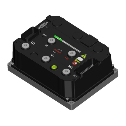
SME AC-X1 User manual

AC Asynchronous/Synchronous Motor Controller
U
US
SE
ER
R
M
MA
AN
NU
UA
AL
L
(
(R
Re
ev
v.
.
1
1.
.0
0:
:
M
Ma
ar
rc
ch
h
2
20
01
17
7)
)
Model
AC
-X1
With 12
-24V Isolated Logic Section
SME S. .A.
Via della Tecnica, n° 40
36071 Arzignano (VI) - ITALY
Phone +39 (0444) 470511
Fax +39 (0444) 451803
E-mail [email protected]om
www.sme-grou .com

ACX1_TAU_SYNC_IsolatedLogic_UserManual_En
Page 2 of 35
SME S. .A. Via della Tecnica 40 Z.I.
36071 ARZIGNANO (VI) ITALY
Phone +39 0444 470511 - Fax +39 0444 451803
[email protected] - www.sme-group.com
Table of Contents
Table of Contents .............................................................................................................................................. 2
1. Introduction .............................................................................................................................................. 4
1.1 About SME Company ....................................................................................................................... 4
1.2 About this manual ............................................................................................................................ 4
1.3 About warning, caution and information notices ............................................................................ 4
1.4 Product warranty information ......................................................................................................... 5
1.5 How to find us .................................................................................................................................. 5
2. AC SmartMotion AC-X1 Overview ............................................................................................................ 6
2.1 Product description .......................................................................................................................... 6
2.1.1 Product Indication Label .............................................................................................................. 7
2.2 General Specifications ...................................................................................................................... 8
2.3 Electrical Specifications .................................................................................................................... 8
2.3.1 Input and Output Ratings ............................................................................................................ 8
2.3.2 Signal Inputs and Outputs........................................................................................................... 9
2.3.3 Interfaces ................................................................................................................................... 12
2.3.4 EMC ............................................................................................................................................ 12
2.3.5 Safety ......................................................................................................................................... 12
2.4 Operating Environment Specifications .......................................................................................... 13
3. Installation and Wiring ............................................................................................................................ 14
3.1 Controller ....................................................................................................................................... 16
3.2 Power Terminals ............................................................................................................................ 20
3.3 Signal .............................................................................................................................................. 21
3.3.1 Digital Inputs .............................................................................................................................. 23
3.3.2 Analog Inputs ............................................................................................................................. 24
3.3.3 Driver Outputs (PWM) ............................................................................................................... 25

ACX1_TAU_SYNC_IsolatedLogic_UserManual_En
Page 3 of 35
SME S. .A. Via della Tecnica 40 Z.I.
36071 ARZIGNANO (VI) ITALY
Phone +39 0444 470511 - Fax +39 0444 451803
[email protected] - www.sme-group.com
3.3.4 Digital Outputs (ON/OFF)........................................................................................................... 26
3.3.5 Speed/Position Sensor Inputs .................................................................................................... 27
3.3.6 Thermal Probe ........................................................................................................................... 28
3.3.7 Serial .......................................................................................................................................... 29
3.3.8 CAN Network ............................................................................................................................. 30
4. Graphical Interface ................................................................................................................................. 31
5. Diagnostic and troubleshooting .............................................................................................................. 32
5.1 Overview ........................................................................................................................................ 32
6. EMC suggestions ..................................................................................................................................... 33
6.1 General overview on EMC .............................................................................................................. 33
6.2 EM emissions ................................................................................................................................. 33
6.3 Immunity to EM disturbances ........................................................................................................ 34
Appendix B Document History ....................................................................................................................... 35

ACX1_TAU_SYNC_IsolatedLogic_UserManual_En
Page 4 of 35
1. Introduction
1.1 About SME Com any
SME group,
founded in 1974, is a high technology company, manufacturer of electronic controllers
and related products for application in battery powered vehicles, particularly forklift trucks and
specialized in the development of AC power controllers.
The group provi
des intelligent and innovative solutions to satisfy market requirements, achieving
worldwide customer satisfaction.
1.2 About this manual
This
manual contains information about a motor controller
100V for high power
circuits and a 12V
This version replaces all previous existing versions of the manual, if any.
1.3
About warning, caution and information notices
Special attention must be paid to the information presented
of information notices when they appear in this manual.
Failure to follow those recommendations may result in dangerous situations or in damages to the
components, for which SME will not respond.
Warnings.
A Warning informs the user of a hazard or a potential hazard
which could result in serious or fatal injury if the precautions or instructions
given in the warning notice are not observed.
Cautions.
A caution informs the reader of a hazard or a potential hazard
which could result in a serious damage to the appliance.
Information Notices.
essential pieces of information to complete or to clarify
paragraph they are placed into.
Interactive Documentation Ti s:
section in the Interactive Documentation
founded in 1974, is a high technology company, manufacturer of electronic controllers
and related products for application in battery powered vehicles, particularly forklift trucks and
specialized in the development of AC power controllers.
des intelligent and innovative solutions to satisfy market requirements, achieving
worldwide customer satisfaction.
manual contains information about a motor controller
intended for electric vehicles using
circuits and a 12V
or 24V isola
ted logic section for low power
This version replaces all previous existing versions of the manual, if any.
About warning, caution and information notices
Special attention must be paid to the information presented
in Warning, Caution and other kinds
of information notices when they appear in this manual.
Failure to follow those recommendations may result in dangerous situations or in damages to the
components, for which SME will not respond.
A Warning informs the user of a hazard or a potential hazard
which could result in serious or fatal injury if the precautions or instructions
given in the warning notice are not observed.
A caution informs the reader of a hazard or a potential hazard
which could result in a serious damage to the appliance.
Information Notices.
An information notice contains additional, not
essential pieces of information to complete or to clarify
the meaning of the
paragraph they are placed into.
Interactive Documentation Ti s:
An advice about where to find the related
section in the Interactive Documentation
SME S. .A. Via della Tecnica 40 Z.I.
36071 ARZIGNANO (VI) ITALY
Phone +39 0444 470511 - Fax +39 0444 451803
[email protected] - www.sme-group.com
founded in 1974, is a high technology company, manufacturer of electronic controllers
and related products for application in battery powered vehicles, particularly forklift trucks and
des intelligent and innovative solutions to satisfy market requirements, achieving
intended for electric vehicles using
ted logic section for low power
circuits.
in Warning, Caution and other kinds
Failure to follow those recommendations may result in dangerous situations or in damages to the
A Warning informs the user of a hazard or a potential hazard
which could result in serious or fatal injury if the precautions or instructions
A caution informs the reader of a hazard or a potential hazard
An information notice contains additional, not
the meaning of the
An advice about where to find the related

ACX1_TAU_SYNC_IsolatedLogic_UserManual_En
Page 5 of 35
SME S. .A. Via della Tecnica 40 Z.I.
36071 ARZIGNANO (VI) ITALY
Phone +39 0444 470511 - Fax +39 0444 451803
[email protected] - www.sme-group.com
1.4 Product warranty information
SME offers a two-year warranty on all the products, unless a different agreement has been put in
place. Refer to the sales agreement or contract under which the motor controller was purchased
for a complete statement of the product warranty.
1.5 How to find us
For any information on commercial and technical issues, please contact either your dealer or SME
at the following address for your region
SME Grou
Head Office
(Euro e)
Via della Tecnica, n°40
36071 Arzignano (VI), Italy
Phone:+39 (0444) 470511
Fax: +39 (0444) 451803
E-mail: sales@sme-group.com
SME Shangai Co. Ltd
(Asia)
No 2, Bldg. 8, 1
st
floor,
388, Xujing Shuanglian Road
201702 Qingpu District
Shanghai, China
Phone: +86 (021) 6025.3818
Fax: +86 (021) 59501502
E-mail: sales@sme-group.com
SME NA Inc
(America)
1404 King St N, Box 154,
St Jacobs
Ontario, Canada
N0B 2N0
Phone: +1 (519) 591-0965
E-mail: sales@sme-group.com

ACX1_TAU_SYNC_IsolatedLogic_UserManual_En
Page 6 of 35
SME S. .A. Via della Tecnica 40 Z.I.
36071 ARZIGNANO (VI) ITALY
Phone +39 0444 470511 - Fax +39 0444 451803
[email protected] - www.sme-group.com
2. AC SmartMotion AC-X1 Overview
Figure 1 - AC-X1
2.1 Product descri tion
The AC-X1 Controller is designed to control AC Asynchronous and Synchronous motors.
Being based on high reliable DCB technology and exceptionally stable Field Oriented Control (FOC)
Algorithm, AC-X1 Controller is a revolutionary and high quality solution for medium power
applications.
The product is suitable for the following range of applications Counterbalanced Lift Trucks,
Cleaning Machines, Golf cars, Aerial Lifts, Tractors, Utility Vehicles, Tow Trucks.

ACX1_TAU_SYNC_IsolatedLogic_UserManual_En
Page 7 of 35
SME S. .A. Via della Tecnica 40 Z.I.
36071 ARZIGNANO (VI) ITALY
Phone +39 0444 470511 - Fax +39 0444 451803
[email protected] - www.sme-group.com
2.1.1 Product Indication Label
The product label shows important data
regarding the specific product.
The meaning of each field is described in the table below.
Field Description
Model Product description.
Type Code SME code for the specific product.
Rating Data It contains the indication of the input voltages and the output currents supplied
by the product.
Batch Number Production batch number (the same value as in barcode below).
Lot Production Month and Year

ACX1_TAU_SYNC_IsolatedLogic_UserManual_En
Page 8 of 35
SME S. .A. Via della Tecnica 40 Z.I.
36071 ARZIGNANO (VI) ITALY
Phone +39 0444 470511 - Fax +39 0444 451803
[email protected] - www.sme-group.com
2.2 General S ecifications
•
Motor Ty e:
AC Asynchronous and Synchronous motors
•
Braking: Regenerative
•
Modulation: PWM (Pulse Width Modulation)
•
Switching Frequency: 9kHz
•
Low R
DS,on
MOSFET
•
16 bits DSP controlling 1 AC motor
•
Integrated Hall Effect Current Sensors
2.3 Electrical S ecifications
2.3.1 In ut and Out ut Ratings
Model Chart for 120/144V version
Model Name
Current
2 min. rating
Power
2 min. rating at 120V
AC-X1 120/144V 250A 250 A
rms
41.6kVA
AC-X1 120/144V 500A 500 A
rms
83.1kVA
Model Chart for 80/100V version
Model Name
Current
2 min. rating
Power
2 min. rating at 80V
AC-X1 80/100V 250A 250 A
rms
27.7kVA
AC-X1 80/100V 375A 375 A
rms
41.5kVA
AC-X1 80/100V 500A 500 A
rms
55.4kVA
AC-X1 80/100V 625A 625 A
rms
69.2kVA
AC-X1 80/100V 750A 750 A
rms
83.0kVA
Notes 2-minute ratings are based on an initial controller baseplate temperature of 25°C and a maximum
baseplate temperature of 85°C.

ACX1_TAU_SYNC_IsolatedLogic_UserManual_En
Page 9 of 35
SME S. .A. Via della Tecnica 40 Z.I.
36071 ARZIGNANO (VI) ITALY
Phone +39 0444 470511 - Fax +39 0444 451803
[email protected] - www.sme-group.com
2.3.2 Signal: In uts and Out uts
•
Digital In uts: 9
•
Analog In uts: 5
•
Digital Out uts (ON/OFF): 2
•
Driver Out uts (PWM): 4
•
Motor S eed Sensor In uts: 2 (A+B Channels or Sin + Cos Inputs)
Refer to following tables for a complete AC-X1 controller K1 and K3 connectors pin-out.
K1 connector in-out for AC-X1 SPECIFICATIONS
Pin Name I/O S ecification Ty ical Function
1 NEGATIVE KEY
SUPPLY I/O Ground Do not exceed 0.5A Negative Key Supply
2 CAN-L CAN BUS CAN-BUS 1 MBit/s max CAN L
3 CAN-L RES CAN BUS Connected to CAN-L with a series
120Ohm Termination resistor
4 DIGITAL INPUT 1 Digital Input
VL<=2V, VH>=4.5V;
Pull-down(active high +12V or +24V)
Pull up(active low)
TO BE ASSIGNED
5 DIGITAL INPUT 2 Digital Input
VL<=2V, VH>=4.5V;
Pull-down(active high +12V or +24V)
Pull up(active low)
TO BE ASSIGNED
6 DIGITAL INPUT 3 Digital Input
VL<=2V, VH>=4.5V;
Pull-down(active high +12V or +24V)
Pull up(active low)
TO BE ASSIGNED
7 DIGITAL INPUT 4 Digital Input
VL<=2V, VH>=4.5V;
Pull-down(active high +12V or +24V)
Pull up(active low)
TO BE ASSIGNED
8 DIGITAL INPUT 5 Digital Input
VL<=2V, VH>=4.5V;
Pull-down(active high +12V or +24V)
Pull up(active low)
TO BE ASSIGNED
9 I/O GROUND I/O Ground Do not exceed 0.5A Negative Logic Supply
10 +12V OUT Supply Output 12V ±5% 200mA max current 12V Supply
11 ANALOG INPUT 1 Analog Input 0÷12V 125KΩ pull-down TO BE ASSIGNED
12 I/O GROUND I/O Ground Do not exceed 0.5A Negative Logic Supply
13 CAN-H CAN BUS 1 MBit/s max CAN H

ACX1_TAU_SYNC_IsolatedLogic_UserManual_En
Page 10 of 35
SME S. .A. Via della Tecnica 40 Z.I.
36071 ARZIGNANO (VI) ITALY
Phone +39 0444 470511 - Fax +39 0444 451803
[email protected] - www.sme-group.com
K1 connector in-out for AC-X1 SPECIFICATIONS
Pin Name I/O S ecification Ty ical Function
14 CAN-H RES CAN BUS Connected to CAN-H Connected to CAN-H
15 LIN Com
Input/Output
19.2kbaud
12V, 1KΩ pull-up LIN Display Connection
16 DIGITAL IN 6 Digital Input
VL<=2V, VH>=4.5V;
Pull-down(active high +12V or +24V)
Pull up(active low)
TO BE ASSIGNED
17
ANALOG INPUT 2 Analog Input 0÷12V 47KΩ pull-down TO BE ASSIGNED
0÷10V OUT Analog Output 0÷10V max load current 5mA TO BE ASSIGNED
18 DIGITAL IN 7 Digital Input
VL<=2V, VH>=4.5V;
Pull-down(active high +12V or +24V)
Pull up(active low)
TO BE ASSIGNED
19 DIGITAL IN 8 Digital Input
VL<=2V, VH>=4.5V;
Pull-down(active high +12V or +24V)
Pull up(active low)
TO BE ASSIGNED
20 DIGITAL IN 9 Digital Input
VL<=2V, VH>=4.5V;
Pull-down(active high +12V or +24V)
Pull up(active low)
TO BE ASSIGNED
21 ENCODER 1A /
ENCODER 1 Sin Peripheral Input
4V 470Ω pull-up, VL<=1.5V, VH>=3.4V /
0,5 – 4,5 mV input
Quad Encoder Channel A /
Sin/Cos Encoder Sin
22
ANALOG INPUT 3 Analog Input 0÷12V 125KΩ pull-down TO BE ASSIGNED
+/- 10V Analog Input 0÷ +10V 125KΩ pull-down, 0÷ -10V
100KΩ pull-down, TO BE ASSIGNED
23 ANALOG INPUT 4 Analog Input 0÷12V 125KΩ pull-down TO BE ASSIGNED
24 KEY SWITCH IN Supply Input
Max = 18V , Min = 7V;
Supply consumption logic board 2A
max + coil return 8A max
Positive Supply of the control
section of the AC-X1
25 +12V COMMON Supply Output (+12V KEY ±0.3V) Do not exceed 8A Positive Common of Auxiliary
26 DRIVER OUTPUT 1 PWM Output Active low
Internal diode to coil return Main Contactor, Brake, Valve
27 DRIVER OUTPUT 2 PWM Output Active low
Internal diode to coil return Main Contactor, Brake, Valve
28 DRIVER OUTPUT 3 PWM Output Active low
Internal diode to coil return Main Contactor, Brake, Valve
29 DRIVER OUTPUT 4 PWM Output Active low
internal diode to coil return Main Contactor, Brake, Valve
30 DIGITAL OUTPUT 1 Digital Output
Active low;
Pull-down;
No internal diode to coil return
Buzzer-Fan-ON/OFF valve

ACX1_TAU_SYNC_IsolatedLogic_UserManual_En
Page 11 of 35
SME S. .A. Via della Tecnica 40 Z.I.
36071 ARZIGNANO (VI) ITALY
Phone +39 0444 470511 - Fax +39 0444 451803
[email protected] - www.sme-group.com
K1 connector in-out for AC-X1 SPECIFICATIONS
Pin Name I/O S ecification Ty ical Function
31 DIGITAL OUTPUT 2 Digital Output
Active low;
Pull-down;
No internal diode to coil return
Buzzer-Fan-ON/OFF valve
32 MOTOR THERMAL
PROBE Analog Input 5V 1KΩ pull-up Motor Temperature Probe
33 ENCODER 1B /
ENCODER 1 Cos Peripheral Input
4V 470Ω pull-up, VL<=1.5V, VH>=3.4V /
0,5 – 4,5 mV input
Quad Encoder Channel B /
Sin/Cos Encoder Cos
34 ANALOG INPUT 5 Analog Input 0÷12V 125KΩ pull-down TO BE ASSIGNED
35 +5V OUT Supply Output 5V ±5% 200mA max current 12V Supply
K3 connector in-out for AC-X1 SPECIFICATIONS
Pin Name I/O S ecification Ty ical Function
1 - - - -
2 DIAGNOSTIC RX
( RS232) Input 38.4-115.2 KBit/s Rx Diagnosis
3 DIAGNOSTIC TX
(RS232) Output 38.4-115.2 KBit/s Tx Diagnosis
4 - - - -
5 I/O GROUND I/O Ground Do not exceed 0.5A Negative Logic Supply
6 - - - -
7 - - - -
8 - - - -
9 +5V Out Bluetooth Supply
±10% 50mA 6Ω output impedance Positive Logic Supply

ACX1_TAU_SYNC_IsolatedLogic_UserManual_En
Page 12 of 35
SME S. .A. Via della Tecnica 40 Z.I.
36071 ARZIGNANO (VI) ITALY
Phone +39 0444 470511 - Fax +39 0444 451803
[email protected] - www.sme-group.com
2.3.3 Interfaces
•
Serial Communication: RS-232
•
CAN:
Protocol: CAN Open
Physical layer: ISO11898-2
Baud rates: 1Mbps, 800kbps, 500kbps, 250kbps, 125kbps, 50kbps
•
Lin Bus
2.3.4 EMC
•
EN12895 (Industrial Trucks – Electromagnetic Compatibility)
•
UNICE Regulation No. 10 Rev.5 ( Uniform provisions concerning the approval of vehicles
with regard to electromagnetic compatibility)
2.3.5 Safety
•
EN1175-1 (Safety of Industrial Trucks – Electrical Requirements)
The vehicle OEM takes full responsibility of the regulatory compliance of the
vehicle system ith the controller installed.

ACX1_TAU_SYNC_IsolatedLogic_UserManual_En
Page 13 of 35
SME S. .A. Via della Tecnica 40 Z.I.
36071 ARZIGNANO (VI) ITALY
Phone +39 0444 470511 - Fax +39 0444 451803
[email protected] - www.sme-group.com
2.4 O erating Environment S ecifications
•
Storage ambient tem erature range: -40°C ÷ +70°C
•
O erating ambient tem erature range: -40°C ÷ +55°C
•
Base late o erating tem erature range: -40°C ÷ +95°C
linear current cutback, beginning at +85°C (boost at 75°C) do n to 50% at +95°C
complete cutoff at +100°C
baseplate temperature is measured internally near the po er MOSFETs.
•
Protection Level: IP65
•
Vibration: Tested under conditions suggested by EN60068-2-6
[
5g, 10÷500Hz, 3 axes]
•
Shock & Bum : Tested under conditions suggested by EN60068-2-27
•
Cold & Heat: Tested under conditions suggested by EN60068-2-1
•
Mechanical size: 210 x 160 x 85 [mm]
•
Weight: 3.5 kg

ACX1_TAU_SYNC_IsolatedLogic_UserManual_En
Page 14 of 35
3. Installation and W
iring
For specific application, refer to the
Interactive Documentation
Figure 2a -
AC
iring
For specific application, refer to the
About Controllers
Area of the
Interactive Documentation
.
AC
-X1 with Asynchronous Motor
iring Diagram
SME S. .A. Via della Tecnica 40 Z.I.
36071 ARZIGNANO (VI) ITALY
Phone +39 0444 470511 - Fax +39 0444 451803
[email protected] - www.sme-group.com
Area of the
iring Diagram

ACX1_TAU_SYNC_IsolatedLogic_UserManual_En
Page 15 of 35
SME S. .A. Via della Tecnica 40 Z.I.
36071 ARZIGNANO (VI) ITALY
Phone +39 0444 470511 - Fax +39 0444 451803
[email protected] - www.sme-group.com
Figure 3b - AC-X1 with Synchronous Motor iring Diagram

ACX1_TAU_SYNC_IsolatedLogic_UserManual_En
Page 16 of 35
3.1 Controller
The C
ontroller contains
connecting,
disconnecting, and handling it
Mechanical Drawing
Working on electrical systems is potentially dangerous; you should protect
Uncontrolled o eration
disconnect the motor or jack up the vehicle and get the drive wheels off the ground before
attempting any work on the motor control circuitry.
Voltage h
azard and high current arcs
and arcs can occur if they are short circuited. Always disconnect the battery circuit before
working on the motor control circuit.
Wear safety glasses and use properly insu
Never energize the system if the terminals
Lead acid batteries
charging or discharging generates hydrogen gas, which can build up and
go around the batteries. Follow the battery
wear safety glasses.
For high resolution diagram, refer to the About Controllers Area of the
Interactive Documentation.
Figure 4 –
Top View
ontroller contains
ESD-sensitive com onents.
Use appropriate precautions in
disconnecting, and handling it
.
AC
Working on electrical systems is potentially dangerous; you should protect
Uncontrolled o eration
some conditions could cause the motor to run out of control
disconnect the motor or jack up the vehicle and get the drive wheels off the ground before
attempting any work on the motor control circuitry.
azard and high current arcs
batteries can supply high voltage and very high power,
and arcs can occur if they are short circuited. Always disconnect the battery circuit before
working on the motor control circuit.
Wear safety glasses and use properly insu
lated tools to prevent shorts.
Never energize the system if the terminals
–
B and +B are not tightly connected.
charging or discharging generates hydrogen gas, which can build up and
go around the batteries. Follow the battery
manufacturer’s safety recommendations and
wear safety glasses.
For high resolution diagram, refer to the About Controllers Area of the
Interactive Documentation.
Top View
SME S. .A. Via della Tecnica 40 Z.I.
36071 ARZIGNANO (VI) ITALY
Phone +39 0444 470511 - Fax +39 0444 451803
[email protected] - www.sme-group.com
Use appropriate precautions in
AC
- X1 To View
Working on electrical systems is potentially dangerous; you should protect
yourself against
some conditions could cause the motor to run out of control
disconnect the motor or jack up the vehicle and get the drive wheels off the ground before
batteries can supply high voltage and very high power,
and arcs can occur if they are short circuited. Always disconnect the battery circuit before
B and +B are not tightly connected.
charging or discharging generates hydrogen gas, which can build up and
manufacturer’s safety recommendations and
For high resolution diagram, refer to the About Controllers Area of the

ACX1_TAU_SYNC_IsolatedLogic_UserManual_En
Page 17 of 35
SME S. .A. Via della Tecnica 40 Z.I.
36071 ARZIGNANO (VI) ITALY
Phone +39 0444 470511 - Fax +39 0444 451803
[email protected] - www.sme-group.com
AC - X1 General View
AC - X1 Side View
AC - X1 Back View
Figure 6 – Side View
Figure 5 – General View
Figure 7 - Back View

ACX1_TAU_SYNC_IsolatedLogic_UserManual_En
Page 18 of 35
SME S. .A. Via della Tecnica 40 Z.I.
36071 ARZIGNANO (VI) ITALY
Phone +39 0444 470511 - Fax +39 0444 451803
[email protected] - www.sme-group.com
Mounting and Re lacement
The Controller meets IP65 environmental protection rating against dust and water.
The mounting location should be carefully chosen in order to be clean and dry, to minimize shock,
vibration, temperature changes and exposure to water & contaminants. If this kind of location
can’t be ensured, then a cover should be used to shield the controller. Cables must be routed to
prevent liquids flowing into the connections. The mounting location should also allow access to all
connections.
The replacement of the Controller must be done with the hand brake engaged, the drive wheels
off the ground, the key switch in off position, battery plug disconnected and the capacitors of the
inverter completely discharged.
The capacitors in the inverter can be discharged by connecting a load between the inverter’s +B
and –B terminals.
Cooling
The Controller must be mounted on a flat, clean and free of paint surface ( external heatsink). Care
must be taken to achieve maximum contact ( i.e. minimum contact thermal resistance) for the
best heat dissipation. When designing a cooling system, please refer to the following instructions
1. Apply thermal compound with a good thermal conductivity on the contact surface of the
controller’s aluminium baseplate and the external heatsink ( thermal grease thickness
+120 ÷ +150μm).
2. The surface finish of the external heatsink should be less than Rz 12μm and the flatness
less than 0.5mm.
Figure 8 – Flatness specifications
Figure 8
-
Planarity

ACX1_TAU_SYNC_IsolatedLogic_UserManual_En
Page 19 of 35
SME S. .A. Via della Tecnica 40 Z.I.
36071 ARZIGNANO (VI) ITALY
Phone +39 0444 470511 - Fax +39 0444 451803
[email protected] - www.sme-group.com
3. A torque wrench shall be used in tightening the 4 mounting screws. The maximum
tightening torque is 6Nm. The order for mounting screws, should follow a “crisscross”
pattern
.
The temporary tightening torque should be set at 20-30% of the maximum rating.
Clearances
For all AC-X1 models 50 mm clearances in front of and behind the AC-X1 are required for airflow;
50 mm clearance above the AC-X1 is required for installation/removal of interface connectors and
wiring.

ACX1_TAU_SYNC_IsolatedLogic_UserManual_En
Page 20 of 35
SME S. .A. Via della Tecnica 40 Z.I.
36071 ARZIGNANO (VI) ITALY
Phone +39 0444 470511 - Fax +39 0444 451803
[email protected] - www.sme-group.com
3.2 Power Terminals
Wiring
The Controller has five Power Terminals, which are clearly marked on Controller’s cover as B+, B-,
U, V, W.
Power Terminals on Controller
Terminal
Meaning
B+ Positive Battery coming from the Main Contactor
B- Negative Battery
U U Motor Phase
V V Motor Phase
W W Motor Phase
The recommended screw torque for fixing the Power Terminals is 15 Nm. This value is written on
the label placed on the cover, exceeding the recommended value may cause damages.
Other manuals for AC-X1
1
Table of contents
Other SME Controllers manuals
Popular Controllers manuals by other brands
Azbil
Azbil MY8045A Specifications & instructions
SE Controls
SE Controls SELA U 24 75 Technical information and operating instructions
Wieland
Wieland podis MCU FAC 3I/W 1.5 operating manual
Nibe
Nibe EME 20 Installer manual
SSS Siedle
SSS Siedle SFC 602-0 Product information

JDS
JDS HomeRunner RBI user manual
