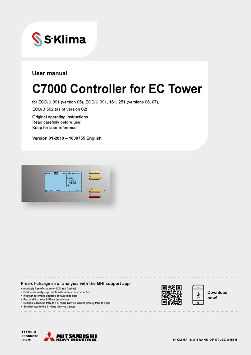
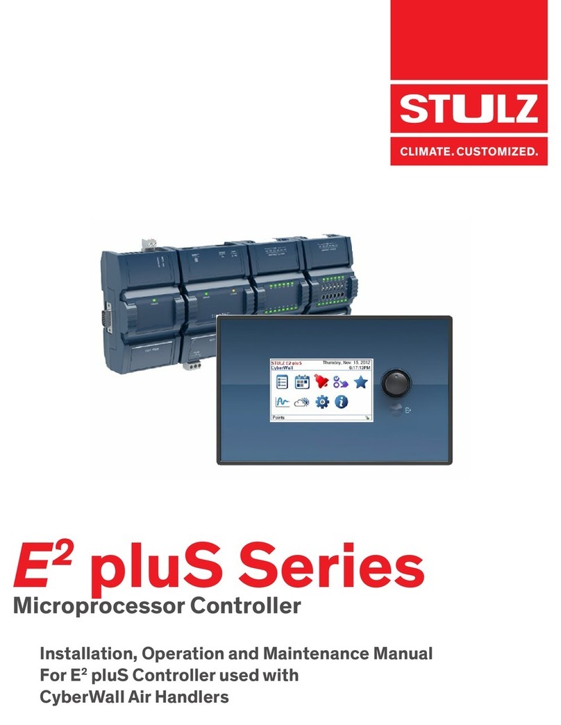
Stulz E2 Series User manual

E2Series
Microprocessor Controller
For STULZ Perimeter
Precision Air Conditioners
Operation Manual

Notice
This document contains information protected by copyright. All rights are reserved. The owner of the equipment for which
this manual is written may photocopy the contents of this manual for internal use only. No part of this document may be
photocopied, reproduced, or translated into another language for use by anyone other than the owner of the equipment
for which this manual is written without the prior written consent of STULZ Air Technology Systems, Inc. (STULZ).
This document contains confidential and proprietary information of STULZ Air Technology Systems, Inc. Distributing or
photocopying this document for external distribution is in direct violation of United States copyright laws and is strictly
prohibited without the express written consent of STULZ.
Unpublished rights reserved under the copyright laws of the United States and of other countries.
Other brands and trade names are trademarks of their respective owners.
© 2017 by STULZ Air Technology Systems, Inc.
Printed in the United States of America.
All rights reserved.
STULZ Air Technology Systems, Inc.
1572 Tilco Drive
Frederick, MD 21704
USA
QUICK START
INSTRUCTIONS
FOR INITIAL START-UP,
SEE SECTION 3.3.

STULZ E2SERIES CONTROLLER FOR PERIMETER SYSTEMS OPERATION MANUAL
iii
Contents
1.0 GENERAL INFORMATION ................................... 1
1.1 Forward................................................................................1
1.2 Safety Summary................................................................1
1.3 Warnings and Cautions ..................................................1
2.0 DESCRIPTION ..................................................... 2
2.1 General.................................................................................2
2.2 Features...............................................................................2
2.2.1 Field Configurable............................................................2
2.2.2 Password Protection.......................................................2
2.2.3 Restorable Setpoint Parameters ................................2
2.2.4 Weekly Timer Feature.....................................................2
2.2.5 A/C Grouping pLAN Operation...................................2
2.2.6 BMS Interface ...................................................................3
2.3 User Interface Terminals................................................3
2.3.1 Graphic Terminal...............................................................3
2.3.1.1 Function Keys....................................................................3
2.3.1.2 Alarms ..................................................................................3
2.3.1.3 Contrast Adjustment .......................................................3
2.3.2 Large Bezel Terminal.......................................................4
2.3.3 Large Bezel Touch Screen Terminal...........................4
2.4 Controller Models.............................................................4
2.4.1 GEN1 Controller Layout ................................................4
2.4.2 GEN2 Controller Layout ................................................4
2.4.3 Expansion I/O Modules..................................................5
2.4.4 Constant Contact UPS Module...................................5
2.4.5 EVD Module .......................................................................5
3.0 Startup ................................................................ 6
3.1 Navigating Controller Screens.....................................6
3.1.1 Menu Selection .................................................................6
3.1.2 Menus...................................................................................6
3.1.3 Display Variables...............................................................7
3.1.4 Cursor Position in Screens............................................7
3.1.5 Modifiable Variables........................................................7
3.2 Password Authorization Levels ...................................7
3.2.1 Password Protected Screens ......................................7
3.2.2 Wrong Password ..............................................................8
3.2.3 Setting the Passwords....................................................8
3.3 Starting the A/C System................................................8
3.4 Setpoint Adjustment........................................................9
3.5 Saving and Restoring Setpoint Parameters.........10
3.6 Alarms ...............................................................................10
3.6.1 Summary Alarm..............................................................10
3.6.2 Customer Alarms ..........................................................11
3.6.3 Custom Alarms ..............................................................11
4.0 Operation .......................................................... 12
4.1 General..............................................................................12
4.2 Temperature/Humidity Sensors ..............................12
4.2.1 Economizer Air Sensors ..............................................12
4.3 Control Signals...............................................................12
4.3.1 On/Off Digital Control..................................................12
4.3.2 Proportional/Integral (P/I) Control..........................12
4.4 Temperature/Humidity Control ................................12
4.4.1 Dewpoint Control ..........................................................12
4.5 Operating Configurations...........................................13
4.5.1 Cooling..............................................................................13
4.5.1.1 Chilled Water/AWS/FC...............................................13
4.5.1.2 Compressor Based Direct Expansion (DX)...........13
4.5.2 Energy Savings Configurations ................................14
4.5.2.1 Economizer......................................................................14
4.5.2.2 Alternate Water Source Cooling (AWS) .................14
4.5.2.3 Free Cooling (FC)...........................................................15
4.5.3 Heating .............................................................................15
4.5.4 Humidifying .....................................................................15
4.5.4.1 Humidifying With Proportional Control..................15
4.5.5 Dehumidifying ................................................................15
4.5.5.1 Reheat...............................................................................15
4.6 Airflow/Fan Speed Control........................................15
4.6.1 Anti-Backdraft Mode (Optional)...............................16
4.6.2 Underfloor/Cold Aisle Pressure Control...............16
4.6.3 Modbus Fan Control (Optional).................................16
4.6.4 Suction Pressure Fan Speed Control
(Optional)..........................................................................16
4.7 Communication With the Controller........................17
4.8 Remote On/Off..............................................................17
4.9 Weekly Timer ..................................................................17
4.10 Dual Power Transfer Switching.................................17
4.10.1 Power Transfer Performed by Phase Monitors ...17
4.10.2 Power Transfer Performed by System
Controller..........................................................................18
4.11 Tandem Compressors Operation.............................18
4.12 Shadow Units..................................................................18

STULZ E2SERIES CONTROLLER FOR PERIMETER SYSTEMS OPERATION MANUAL
iv
5.0 Menu SCREENS ................................................ 20
5.1 Main Menu .......................................................................20
5.2 Information Menu ..........................................................20
5.2.1 Operating Conditions...................................................20
5.2.2 Shadow Unit Alarms .....................................................21
5.2.3 Return Sensor.................................................................21
5.2.4 Compressor Status- (DX based systems).............21
5.2.4.1 Optional Compressor Status Fields........................21
5.2.5 Remote Sensor ..............................................................22
5.2.6 Remote Temperatures.................................................22
5.2.7 Water Temperature- (CW/FC/AWS based
systems)............................................................................22
5.2.8 Setpoint Values ..............................................................22
5.2.9 Fans and CW Valve .......................................................22
5.2.10 Economizer Information Menu Screens ................23
5.2.11 Under Floor Pressure...................................................23
5.2.12 Differential Air Pressure Sensor...............................23
5.2.13 Dewpoint Sensor...........................................................23
5.2.14 Air Speed Sensor...........................................................23
5.2.15 User Sensors ..................................................................24
5.2.16 KVA Display.....................................................................24
5.2.17 Differential Water Pressure .......................................24
5.2.18 Air Flow Rate...................................................................24
5.2.19 Water Flow Rate ............................................................24
5.2.20 Atmospheric Pressure.................................................24
5.2.21 Dual Power ......................................................................25
5.2.21.1 Dual Power with UPS...................................................25
5.2.21.2 Special Dual Power.......................................................25
5.2.22 Group Information Menu Screens ...........................26
5.2.23 Modbus Fan Data..........................................................27
5.2.24 Power Meter Data .........................................................27
5.2.25 Electronic Expansion Valve (EEV) Status..............27
5.2.26 CW Valve Feedback......................................................27
5.2.27 Software Version/Date ...............................................27
5.3 Alarm Log.........................................................................28
5.3.1 Alarms ...............................................................................28
5.3.2 Non-Critical Alarms......................................................28
5.3.3 Critical Alarms.................................................................28
5.3.4 Alarm Screen Messages.............................................28
5.4 Control Menu ..................................................................31
5.4.1 Setpoint Screens...........................................................32
5.4.1.1 High Pressure Auto Reset (Optional)......................32
5.4.1.2 Max GPM..........................................................................32
5.4.2 Alarm Setpoint Screens ..............................................32
5.4.3 Clock Screens ................................................................34
5.5 Service Menu..................................................................35
5.5.1 Cool ...................................................................................35
5.5.1.1 DX Cooling Screens......................................................35
5.5.1.2 CW Cooling Screens ................................................... 36
5.5.2 Heat ...................................................................................36
5.5.3 Humidity............................................................................36
5.5.4 Alarms ...............................................................................37
5.5.5 Sensors.............................................................................37
5.5.6 Blower...............................................................................37
5.5.6.1 Blower Set-up ................................................................37
5.5.6.2 CW Fan Set-up...............................................................37
5.5.6.3 Static Pressure Set-up................................................38
5.5.6.4 Modbus Fan Control and Data Monitoring ...........38
5.5.7 Options Menu .................................................................39
5.5.7.1 Control, Startup .............................................................39
5.5.7.2 Unit Timers ......................................................................39
5.5.7.3 T/H Offset Scaling .......................................................40
5.5.7.4 Auto Flush Cycle ...........................................................40
5.5.7.5 Barometric Pressure ..................................................40
5.5.7.6 Dual Power .....................................................................40
5.5.7.7 Custom Alarm Setup ..................................................41
5.5.7.8 Economizer Test ............................................................44
5.5.8 Digital In............................................................................44
5.5.9 Run Hours........................................................................45
5.5.10 BMS Communication...................................................45
5.5.11 Work Group Screens....................................................45
5.5.12 Save Configuration .......................................................45
5.5.13 Factory Menu..................................................................46
6.0 Economizer Operation ..................................... 47
6.2 Economizer Service Menu Screens........................48
6.2.1 Economizer Test ............................................................48
6.1 Economizer Information Menu Screens ................48
6.1.1 Economizer Return Air Sensor..................................48
6.1.2 Economizer Outside Air Sensor................................48
6.3 Enabling Economizer Operation...............................49
6.3.1 Economizer Option Screen ........................................49
6.3.2 Economizer Screen Two..............................................50
6.3.3 Economizer Screen Three..........................................50
7.0 Communication With the Controller ............... 50
7.1 Work Groups...................................................................50
7.1.1 Capacity Assist...............................................................51

STULZ E2SERIES CONTROLLER FOR PERIMETER SYSTEMS OPERATION MANUAL
v
7.1.2 Standby.............................................................................51
7.1.3 Unit Rotation...................................................................51
7.1.3.1 No Rotation .....................................................................51
7.1.4 Out of Service .................................................................51
7.2 Setting Up a Work Group............................................52
7.2.1 Configure the Terminal Address...............................52
7.2.2 Configure the I/O Board pLAN Address ..............52
7.2.3 Assign the Terminal to the Controller......................53
7.2.4 Fault messages .............................................................53
7.2.5 Displaying the Network Status and Firmware
Version ..............................................................................53
7.2.6 Configure Work Groups ..............................................54
7.2.6.1 Group Sensor Values....................................................60
7.2.6.2 Group Alarms .................................................................. 60
7.2.6.3 Lead Controller Group Sensors................................60
7.2.6.4 Group Sensor Status....................................................60
7.3 BMS Communication...................................................61
7.3.1 Direct BMS Control.......................................................61
7.3.2 BMS Communication...................................................61
8.0 Maintenance and repairs.................................. 62
8.1 General Maintenance...................................................62
8.2 Troubleshooting.............................................................62
8.3 Repair Procedures........................................................62
8.3.1 General..............................................................................62
8.3.2 Component Replacement..........................................62
8.4 Control I/O Module Signal LED's.............................63
9.0 Product Support............................................... 64
9.1 Factory Authorized Start Up/Warranty
Inspection ........................................................................64
9.2 Technical Support .........................................................64
9.3 Obtaining Warranty Parts ...........................................64
9.4 Obtaining Spare/Replacement Parts ....................64
Glossary....................................................................... 66
Figures
Figure 1. BMS Interface Ports ..................................................3
Figure 2. GEN1 Controller..........................................................4
Figure 3. GEN2 Controller..........................................................4
Figure 4. Menu Selections..........................................................6
Figure 5. Dewpoint Control.....................................................13
Figure 6. Cooling On/Off Cycle.............................................14
Figure 7. AWS/FC/DX Operation.........................................14
Figure 8. Service Menu Selections.......................................35
Figure 9. Economizer Operation............................................47
Figure 10. Default Economizer Zone .....................................48
Figure 11. Example Economizer Zone...................................49
Figure 12. Configuring Multiple A/C Units...........................50
Figure 13. BMS Connection Types .........................................61
Tables
Table 1. Tandem Compressor Operation Example.............18
Table 2. Factory Default Setpoints ..........................................46

STULZ E2SERIES CONTROLLER FOR PERIMETER SYSTEMS OPERATION MANUAL
vi

STULZ E2SERIES CONTROLLER FOR PERIMETER SYSTEMS OPERATION MANUAL
1
1.0 GENERAL INFORMATION
1.1 Forward
The microprocessor based, STULZ E2Series Controller
covered by this manual is designed and manufactured by
STULZAirTechnology Systems, Inc. (STULZ) utilizingthe latest,
state-of-the-art control technology. Recognized as a world
leader, STULZ provides precision A/C systems and controllers
manufactured with the highest quality craftsmanship using
the finest materials available in the industry. The controller
will provide years of trouble free service if it is operated and
maintained in accordance with this manual. Damage to the
unit from improper installation, operation or maintenance is not
covered by the warranty.
This manual is applicable to the STULZ E2Series Controller
software versions for CyberAir family systems up to v3.24,
released inJuly, 2015. It contains information forthe operation
ofthe controller. STUDYthe instructionscontained in thismanual.
They must be followed to ensure properoperation. Spare parts
are availablefrom STULZto ensure continuous operation. Using
substitute parts or bypassing electrical components in order
to continue operation is not recommended and will VOID THE
WARRANTY. Dueto technological advancements, components
are subject to change without notice.
STULZ E2Series Controllers are designed primarilyto precisely
operate, control and monitor STULZ precision air conditioning
systems. Any use beyond this is deemed to be not intended.
STULZ is not liablefor anydamage resultingfrom improperuse.
All STULZ E2Series Controllers are designed for indoor use.
1.2 Safety Summary
Read and understand all instructions in this manual relating to
the specific function to be performed prior to starting the task.
Carefully read and understand all notes, cautions andwarnings
contained in this manualthat pertain to thetask to be performed.
Warnings indicate potentialthreatto personnel safety. Cautions
indicate potential threat of damage to equipment.
Carefully read and understand allWARNING and/or CAUTION
labels located on the unit.
1.3 Warnings and Cautions
STULZ uses NOTES along with CAUTION and WARNING
symbols throughout this manual to draw attention to
important operational and safety information.
A bold text NOTE marks a short message in the text to
provide an alert to an important detail.
A bold text CAUTION safety alert appears with information
that is important for protecting the equipment and its
performance. Be especially careful to read and follow all
cautions that apply to the application.
A bold text WARNING safety alert appears with information
that is important for protecting personnel from harm and
the equipment from damage. Pay very close attention to
all warnings that apply to the application.
A safety alert symbol accompanies a general WARNING
or CAUTION safety statement.
A safety alert symbol accompanies an electrical shock
hazard WARNING or CAUTION safety statement.
The following statements are general guidelines followed by
warnings and cautions applicable throughout the manual.
CAUTION
Prior to operating the unit, read and understand
all instructions, recommendations and guidelines
contained within this manual.
CAUTION
All adjustments, maintenance and/or repairs must be
performed by a qualified technician.
NOTE
We recommend contacting STULZ Product Support
for assistance with adjusting or servicing the A/C unit.
WARNING
If a fault occurs when operating the A/C unit or
adjusting control parameters, it must be corrected
immediately in accordance with the troubleshooting
instructions for the A/C unit.
CAUTION
Equipment may contain components subject to
Electrostatic Discharge (ESD). Before attempting to
mount or service these electronic devices, ensure you
have no charge built up by touching a ground source.
When possible, use a wrist-grounding strap when
working on or near electronic devices.

STULZ E2SERIES CONTROLLER FOR PERIMETER SYSTEMS OPERATION MANUAL
2
2.2.2 Password Protection
Access to the Info menu and Alarms log is allowed without the
use of a password. The controller is programmed to recognize
predetermined security levels before allowing accessto display
screens containing criticalvariables. Four secured menu levels
(Control, Service, Factory and Configuration) support unique
passwords that must be entered to access the menu screens
so only authorized personnel mayperform modifications to the
settings. This Manual covers Information, Control and Service
levels only. The Factory and Configuration levels are covered
in a separate manual.
2.2.3 Restorable Setpoint Parameters
Upon initial start-up the A/C system operates using the
setpoints programmed by the factory. New operating
parameters maybe entered in the Control level and the system
will then operate accordingly. The newsetpoints maybe stored
as Customer default setpoints in the Service>Save Cfg menu
screen.The primary setpoints entered bythe factorystill remain
stored in the controller's memory as Factory setpoints.
The setpointsforthe system may be re-adjusted inthe Control
level at any time. Use the Service>Save Cfg menu screen to
restore the setpoints to the Customer Default setpoint values
or to the original Factory setpoint values.
2.2.4 Weekly Timer Feature
The weekly timer allows the user to set up an operating
schedule to automatically scale back or shut down the air
conditioner during low demand or unoccupied periods. This is
an energy saving feature offering the user the ability to create
an operating schedule tailored to the needs of the building. An
evening (night-setback) schedule mayalso be created, allowing
the A/C unit to operate at night with relaxed temperature/
humidity setpoints and offsets.
2.2.5 A/C Grouping pLAN Operation
MultipleA/C units, consisting of upto eight (8) STULZ precision
air conditioners equipped with STULZ E2Series controllers,
can be connected (grouped)throughthe pLAN. The pLAN puts
all displays and controllers on a single RS485 connection to
allow information to be exchanged among all the controllers.
Each display and controller has a unique, predefined address.
Each controller in agroup can be configured as “Active”, “Assist”
or “Standby”. Units that are “Active” are used to maintain the
setpoints. Units that are “Assist” are used to step in if the
Active units are unable to maintain the setpoints. Units that
are “Standby” are used as backup units in case of a failure of
either anActive orAssist unit.The role oflead controller can be
assigned to one ofthe ActiveAC units. Rotation ofthe lead unit
function tothe next Active unit can be set to occur hourly, daily
at a specific time or weekly on a specific day at a specific time.
This allows the units within the group to be operated for equal
times on a periodictime basis. See section 7.0 formore details.
2.0 DESCRIPTION
2.1 General
The advanced microprocessor based, STULZ E2Series
controlleris a highlyversatile and flexibleA/C system controller.
It is designed primarily for STULZ Precision Air Conditioners.
The controller is equipped with flexible software capable of
meeting the specific needs of the application. The controller
is completely programmed at the factory and therefore, most
applications will require no field set-up. However, the default
setpoints and their ranges are easily viewed and adjusted
from the user interface display. The program and operating
parameters are permanently stored on flash memory in case
of power failure.
The controlleris designed to manage temperature and humidity
levels to a user defined setpoint via control output signals to
theA/C system. Control parameters havevariable outputs from
0 to 100% of the full rated capacity. The controller receives
inputs for the measurable control conditions (temperature
and relative humidity) via return air or room mounted sensors.
The internal logic determines ifthe conditions require cooling,
heating, humidification or dehumidification. Control setpoints
are established to maintain the room's designed conditions.
The controller responds accordingly to changes and controls
the output(s) to the air conditioning system so temperature/
humidity conditions reach the user defined control setpoints.
The STULZ E2Series controller continually monitors
conditions and maintains setpoints utilizing STULZ’s unique
psychrometric control method. The controller logically
examinesthe combination oftemperature and relative humidity
(dewpoint) and determines the proper control of cooling,
heating, humidification and dehumidification to move the
actual conditions to within the boundaries of the temperature/
humidity setpoints as they would appear on a psychrometric
chart. It avoids scenarios where the cooling unit might both
cool and humidify the air when cooling alone will achieve the
desired result.This control method results in higheroperational
efficiency and shorter component run-times.
2.2 Features
2.2.1 Field Configurable
The program for the STULZ E2Series controller is field
configurable, allowing the operator the capability of selecting
control setpoints specific to the application. Operator interface
forthe STULZ E2Series controlleris providedvia an attractive,
door mounted user interface display panel. The display panel
has a backlit LCD graphical displayand function keys giving the
user complete control and monitoring capability ofthe precision
cooling system. The menu driven interface provides users
the ability to scroll through and enter various menu screens.
Monitoring of room conditions and A/C system operation is
allowed without entering a password. Modifications to the
control setpoints require the use of a password.

STULZ E2SERIES CONTROLLER FOR PERIMETER SYSTEMS OPERATION MANUAL
3
2.2.6 BMS Interface
The STULZ E2Series controller may incorporate a
communication interface port (Figure 1) that can be field
connected to a Building Management System via Modbus,
BACnet, SNMP or HTTP protocol as configured by the factory.
A controllerinterfacedto a network must be configured for BMS
communication.
BACnet IP, BACnet Ethernet,
HTTP, SNMP, & Modbus IP
BACnet MS/TP
Modbus RTU
2.3 User Interface Terminals
Several user interface terminals are available with STULZ E2
Series controllers. The A/C unit may be equipped with a large
bezel terminal typically mounted on the door ofthe unit or a small
bezel terminal (termed "graphic terminal") which may be door
mounted or remotely mounted to a wall or control panel. See the
following sections for an overview of the user interface display
panels available.
2.3.1 Graphic Terminal
The STULZ graphic terminal features an easy to read, backlit
liquid-crystal alphanumeric display equipped with LED
illuminated function keys.The screensthat appear onthe display
present data that originates from the controller. The controller
is operated via 6-key menu-driven loop structure and offers
an alarm log plus four different interface menu levels to the
operator: Information, Control, Service, and Factory. These
menus permit the user to easily view, control and configure
operating parameters for the A/C unit (see Menu Selections,
Figure 4).
As an option, the graphic terminal may be shipped loose
for remote mounting. It may be located directly on a wall or
control panel using the mounting kit provided. Install the
terminal in a secure area where it cannot be tampered with. A
30 foot long RJ11 telephone type cable harness is provided
for interconnecting the display to the controller. Refer to the
electrical drawing supplied with the unit for details on the
interconnecting field wiring.
2.3.1.1 Function Keys
KEY FUNCTION
Accesses the active alarm screen(s)
Silences audible alarms
Resets active alarms in the alarm menu
Prg Accesses the main menu
Illuminates yellow when unit is on
Esc Returns to the previous menu level
Cancels a changed entry
Steps back to the previous screen in display menu
Changes (increases) the value of a modifiable field
Starts/Stops operation (if "Auto-On Powerup" isn't
enabled)
Moves the cursor into a modifiable field
Accepts current value of a modifiable field
Steps to the next screen in display menu
Changes (decreases) the value of a modifiable field
2.3.1.2 Alarms
Alarm conditions activate a red LED indicatorthat backlights the
alarm function key. As an option, an alarm condition mayalso be
enunciated byan audible alarm signal. An alarm is acknowledged
by pressing the alarm key. This calls up alarm display screen(s)
that provide a text message detailing the alarm condition(s).
After an alarm condition is corrected, the alarm can be cleared
by pressing the alarm key.
2.3.1.3 Contrast Adjustment
Press and hold the ( ) and (Prg) keys; then use the Up ( ) and
Down ( ) keys to adjust the contrast.
Figure 1. BMS Interface Ports

STULZ E2SERIES CONTROLLER FOR PERIMETER SYSTEMS OPERATION MANUAL
4
2.3.2 Large Bezel Terminal
The large bezel terminal is typically mounted on the door of
the A/C cabinet. It features the same backlit liquid-crystal
alphanumeric display screens that the graphicterminaluses.
A round membrane type keypad is provided to the right of the
display screen to navigate through the controller menus and
adjust operating parameters.The symbols on the round keypad
are operationally identical to the function keys on the graphic
terminal (see section 2.3.1.1).
When theA/C unit is on, a soft blue light illuminatesthe "Status"
region on the right side of the terminal indicating normal
operation. If the color of the "Status" region changes to red, it
indicates an alarm condition. As with the graphic terminal, an
alarm is acknowledged by pressing the alarm symbol on the
round keypad. After an alarm condition is corrected, the alarm
can be cleared by pressing the alarm symbol again. This resets
the A/C system and turns the color in the status region back
to blue.
2.3.3 Large Bezel Touch Screen Terminal
A large bezel terminal with touch screen is available with
certain A/C models. If the A/C unit is equipped with a touch
screen terminal, refer to the addendum OZU0074 (provided
under separate cover) for supplemental instructions.
2.4 Controller Models
The controller is a microprocessor with I/O modules mounted
inside the A/C system electric box (see Figure 2 and Figure 3).
The controllercontains the softwarethat managesthe operating
parameters of the A/C system. Several I/O module types are
available depending upon the options that are needed with the
air conditioning system.
2.4.1 GEN1 Controller Layout
The GEN1 controller is shown in Figure 2.
12
43
6
5
7
The controller features called-out in Figure 2 are:
1. RJ11 telephone connector (J10) for display panel.
2. RS485 Connection for pLAN (J11).
3. Hatch for BMS or network interface port (see Figure 1).
4. Power on LED (Yellow).
5. Signal LEDs (Red, Yellow, Green). See Section 8.4.
6. Hatch for expansion I/O module(s).
7. Power connector (J1).
2.4.2 GEN2 Controller Layout
The GEN2 controller has additional input/output terminals for
expanded capability. It may be expanded with a built-in EVD
driver, utilized when electronic expansionvalve(s) are provided.
The GEN2 controller is shown in Figure 3.
12
54
8
6
93
7
Figure 2. GEN1 Controller
Figure 3. GEN2 Controller

STULZ E2SERIES CONTROLLER FOR PERIMETER SYSTEMS OPERATION MANUAL
5
The controller features called-out in Figure 3 are:
1. RJ11 telephone connector (J10) for display panel.
2. RS485 Connection for pLAN (J11).
3. Hatch for USB ports.
4. Hatch for BMS or network port.
5. Power on LED.
6. Overload LED.
7. Controller pLAN Address Display.
8. Hatch for expansion I/O module(s).
9. Power connector (J1).
2.4.3 Expansion I/O Modules
The controller's capabilities may be enhanced by the addition
of expansion I/O modules which are DIN rail mounted in the
electric box. They are typically utilized when selected optional
features are purchased. Expansion I/O modules are used
to enable additional alarms, additional blowers, air speed
monitoring or air pressure monitoring.
2.4.4 Constant Contact UPS Module
An optional Constant Contact UPS module provides shortterm
power for the controller should there be an interruption to, or
inconsistencywith, the main powersource. Ifmain poweris lost,
the Constant Contact module provides 32 VDC control power
to the controller. The controller will not have to reboot due to
a power interruption. This allows the controller to continue
monitoring sensor input signals and maintain communications
with a BMSfor upto one minute.The Constant Contact module
requires no routine maintenance as there are no batteries that
need to be replaced.
CAUTION
When the power supply to the equipment has been
shut offto service the unit, be awarethat the Constant
Contact UPS module in the electric box still contains
stored electric power up to 32 VDC. This voltage will
also be present in circuitsthat are electricallycommon
to the constant contact module.
2.4.5 EVD Module
An electronic expansion valve (EEV) may be used on certain
compressorbased models. Control ofthe EEV is accomplished
with an electronic valve driver module (EVD). The EVD may be
a separate expansion module or it may be incorporated into a
GEN2 controller, depending on the I/O configuration.

STULZ E2SERIES CONTROLLER FOR PERIMETER SYSTEMS OPERATION MANUAL
6
3.0 STARTUP
3.1 Navigating Controller Screens
3.1.1 Menu Selection
The STULZ E2Series controller provides five user selectable
menus needed to view operating data and enter setpoints for
the system (see Figure 4).These menus maybe accessed from a
scrolling Main menu screen by pressingthe Program (Prg) key.
Scroll between adjacent menu selectionswithin the Main menu
by use of the Up ( ) and Down ( ) arrow keys.
When the desired menu is centered in the screen with bold
capital letters and an arrow symbol pointing towardsthe Enter
() key, press the Enter ( ) key to access that menu. Menu
screens located within the designated menu selection may be
accessed using the Up ( ) and Down ( ) arrow keys. Access to
some menus are protected by a built in security protocol and
requires the use of a password to gain access.
3.1.2 Menus
From the Main screen press the Program (Prg) key to select from among the five menus shown in Figure 4.
MAIN
SCREEN
*Call STULZ Product Support for Assistance
MAIN MENU
Control
SERVICE
Factory
MAIN MENU
Alarm Log
CONTROL
Service
MAIN MENU
Info
ALARM LOG
Control
MAIN MENU
Factory
INFO
Alarm Log
MAIN MENU
Service
FACTORY
Info
Press ( ) or ( ) Key
01/01/09 00:00:00
00.0°F
00%rh
dp 00.0°F
Unit ON
MENU SCREENS DISPLAY
INFO MENU Basic status information, no
password needed (Level 0)
ALARM LOG
Logged Alarms in chronological
sequence, no password needed
(Level 0)
CONTROL MENU Basic user values i.e. setpoints.
Level 1 password required
SERVICE MENU Advanced user values i.e. offsets
Level 2 password required
FACTORY MENU
(*Access is limited)
Factory values i.e. sensor scaling
*Level 3 password required
CONFIGURATION
MENU
(*Access is limited)
Used to set the STULZ A/C
model being controlled and the
basic features for that model
*Level 4 password required
From the Main Menu Screens
Press Enter ( ) Key To Access
The Menus
Press "Prg" Key
Figure 4. Menu Selections

STULZ E2SERIES CONTROLLER FOR PERIMETER SYSTEMS OPERATION MANUAL
7
3.1.3 Display Variables
The user interface display panel provides screens with three
(3) different forms of both the read only and the modifiable
variables:
• Integers are displayed either as signed or un-
signed numbers.
• Analog values are displayed eitheras signed or un-
signed numbers with 1 decimal point of precision.
• Dual-State can be toggled betweentwovaluesfor
example, On/Off, Yes/No, and so on.
• Word Variables have a unique text message for
each of the variable's possible choices.
3.1.4 Cursor Position in Screens
The following display screen is shown as an example after
accessing a newmenu using thefunction keys.The name ofthe
menu is the line inthe upper-most field ofthe screen.Aflashing
window also appears in the left side of the upper-most field
indicating you're in the top level of that menu.
CONTROL MENU
Alarm Set
CLOCK
Version
Flashing
Window
From this position the Up ( ) and Down () arrow keys may be
used to access additional selections within the current menu.
Each screen supports specific functions. Pressing the Enter (
) key allows access to the selected display screens to adjust
any ofthe modifiable fields. If a screen with modifiable values is
accessed, the Enter ( ) keymay be pressed to insert aflashing
cursor in the modifiable fields within that screen.
Flashing
Cursor
SET CLOCK
Time: 00:00
Date: 00/00/0000
Day: XXXXXXX
If the flashing cursor is located in a modifiable field, the value of
the field will be changed with the use of the Up ( ) and Down (
) arrow keys. When the Enter ( ) key is pressed, the new value
is saved and the cursor moves to the next modifiable field. After
entering the last modifiable field within a screen, pressing the
Enterkeyremovesthe cursor and theflashing window reappears
in the left-hand corner of the upper-most field of the current
screen. From here, advancement to the next adjacent menu
screen occurs when the Up or Down key is pressed. Successive
use of the Enter key will advance the cursor through the various
modifiable fields of the display screen eventually returning to
the first field.
Values that are already correct may simply be skipped over by
using the Enter ( ) keywithout modification ofthe variable.The
current value, if not changed, will be retained after pressing the
Enter ( )key. Valuesforfields being adjusted will automatically
wrap when adjusted beyond the high or low limit established for
that field.
Whenever the flashing cursor is located in a modifiable field,
pressing the Escape (Esc)key one time returns the user to the
next menu level up. Each successive use of the Escape key
returns the operator to the next menu level up until the Main
screen is reached.
3.1.5 Modifiable Variables
SET CLOCK
Time: 00:00
Date: 00/00/0000
Day: XXXXXXX
Modifiable
Variable
Forthe purpose ofthis manual the examples ofuser modifiable
variables within display screens will be denoted by bold text.
(Please note the actual display maynot use bold text.) Pressing
the Enter ( ) key accepts the value displayed and advances
the cursor to the next modifiable field. The Up ( ) or Down ( )
key may be used to modify the values of these fields.
If the modifiable field is a positive number, the positive value is
indicated by the absence of a negative symbol. The negative
symbol will be displayed to the left of the first digit for negative
numbers.
3.2 Password Authorization Levels
Access to a menu may be requested from the main menu.
Modifiable control screens have variables that affect system
performance. Improper settings may result in erratic operation
and possible system failure or damage. Anyone is allowed
direct access to the Info and Alarm log display menus with no
security password
Only authorized personnel who possess a thorough
understanding of the system operation should perform
modifications to secured menu settings (Control, Service,
Factory and Configuration). The screens must have accurate
variables entered otherwise erratic operation may occur.These
menus are configuredwith password protection,thus requiring
a higher level of authority to access them.
3.2.1 Password Protected Screens
Uponfirst attemptingto select a secure menu in a given session,
the Enter Password screen will be displayed. This screen
displays the current security level authorized in the lower field.

STULZ E2SERIES CONTROLLER FOR PERIMETER SYSTEMS OPERATION MANUAL
8
Enter Password: 0
Level:0 (Current
Security
Level)
Enter Password Screen
A session is defined as from the time access is gained to a
secure menu until 300 seconds (five minutes) elapses with no
key activity. Security access will be terminated at this point and
the password will have to be re-entered to gain access. The
menus that may be password protected by the user are the
Control and Service menus. The Factory level menu screens
are also password protected, however the password is set at
the factory to limit access.
It is intended that access to the Factory menu screens only be
granted while the user is working with the guidance of STULZ
Product Support (see Section 9.0) because incorrect settings
made at that level could unintentionallydamage the equipment.
The level of authority is established by entering the proper
password for a given security level. The controller is shipped
from the factory with preset passwords for all of the security
levels.
Operatorswho are allowed accessto the Service menu (level 2)
for example, must know the password to enter that level. If the
entered password equals orexceedsthe level requested during
a given session,the operator is allowedto accessthe requested
menu. For example, if the entered password allows access to
level 2 and the Control menu (level 1) is requested, access will
be allowed. Ifthe entered password authoritylevel is lowerthan
the level requested,the words"WRONG PASSWORD"will appear
for several seconds at the bottom of the screen.
3.2.2 Wrong Password
Enter Password: 0
Level:0
** WRONG PASSWORD **
The WRONG PASSWORD message is displayed any time an
incorrect password is entered andthe Enter( ) key is pressed.
Ifthe “Wrong Password”message appears, use ofthe Enter ( )
key will return the operator to the Enter Password field.
A requested menu is displayed any time a valid password is
entered and the Enter ( ) key is pressed.
3.2.3 Setting the Passwords
The initial passwords are set by the factory to 1for the Control
menu and to 2 for the Service menu. In the Service>Save Cfg
menu, the operator is allowed to change the passwords for
the Control and Service menus. If changed, from that point on,
access mayonly be gainedto that menu bypersonnel who know
the new password.
3.3 Starting the A/C System
CAUTION
Ensure all system hookupsto the airconditioner(s) are
completed and that power is available.
1. Turn the main power disconnect switch for the A/C unit to
ON. Upon applying control power, the controller display
function keys illuminate and the controller begins con-
ducting internal diagnostics to confirm functionality. The
controller monitors the alarm inputs and alarm logic to de-
termine if it's safe to startthe unit. After about 30 seconds
the Main screen is displayed. The Main Screen is a status
screen displaying the current date,time,temperature, rela-
tive humidity and dewpoint conditions. It also indicates the
current system operating status.
2. Ifthe controller is configured for Automatic Onopera-
tion (standard), astatus message Unit Onthen appears in
the displayand the controllerbegins the start up sequence.
NOTE
The A/C unit may be turned off at anytime by pressing
and holding the Enter ( ) key for 3 seconds.
01/01/09 00:00:00
00.0°F
00%rh
dp 00.0°F
Unit On
Main Screen
3. If the status message OFF - Manual Restart Req
appears instead of Unit On, turn the air conditioner on by
pressing the Enter ( ) key. In this case the Automatic On
feature may not be enabled in the Service>Options menu
(see Section 5.5.7.1).
Other status messages that may appear at the bottom of
the screen are:
Off by Remote Shutdown - Indicates the Remote
Start/Stop feature is enabled and requires a remote start
switch to be turned On.
Off by Clock - Unit is off by time clock schedule.
Off by Network - Indicates the unit is part of a group
and is off due to a grouping priority command such as a
compressor alarm or loss of airflow
or,
the BMS communication feature is enabled and the unit
received a network signal to pause operation.

STULZ E2SERIES CONTROLLER FOR PERIMETER SYSTEMS OPERATION MANUAL
9
Off by Internal Alarm - Unit is offdue to a group
alarm condition. (Only active with grouped units.)
Off by Loss of Power - Displayed on units with
dual power sources and a power loss occurs. It is removed
when a switch over to a good power source occurs.
Off by Damper Failure - If equippedwith a damper
and the damper failed to open.
Off by Shadow - If configured to be a shadow unit
and the main unit is off.
Off by Water Alarm- Water alarm as configured (I.E.
leak detected, CW/WG alarm, humidifier alarm).
4. If damper control is enabled, a delay occurs to allow
the dampers to open before starting the blower(s). The
blower(s) are allowed to begin operating 20 seconds af-
ter Unit On appears, or after the damper enable delay
expires (if applicable). The STULZ logo in the display is
replaced with a blower symbol and a message Unit
ON NO Airflow appears.
Airflow is monitored by an air proving sensor. Appro-
priate airflow must be detected before the controller
outputs are enabled to perform cooling, heating, hu-
midification and dehumidification. Upon detecting a loss
of airflow, the controller shuts down all system outputs
(except the blowers and damper enable) and signals an
alarm.
5. When adequate airflow is detected,the status message "No
Airflow" disappears and the message "Unit On" remains in
the display. The controller automatically enables the con-
trol outputs as defined by the A/C system configuration
and records the date and time power is re-initialized in the
alarm history log.
6. Ifthe actual room conditions are notwithin the range ofthe
programmed setpoints, the system will begin operating in
the mode(s) neededto reachthe setpoints (cooling heating,
humidifying or dehumidifying). Symbols (shown below) ap-
pear in the displayto indicate the active operating mode(s).
= Blower On
= Cooling Enabled (Compressor 1)
= Cooling Stage 2 Enabled (Compressor 2)
= Cooling Stage 3 Enabled (Compressors 1b +2)*
= Cooling Stage 4 Enabled (Compressors 1a +1b
+2)*
(* Tandem compressor applications; see Section 4.11)
= Cooling Enabled (CW Based Units)
= Cooling Enabled (FC/AWS Based Units)
= Heating
= Two Stages of Heating
= Three Stages of Heating
= SCR Heat
= Humidifying
= Dehumidifying
= Compressor/Humidifier/Heater Locked Out
by BMS
/ = CW Coil Flush Cycle On
NOTE:
Bar graph icons are used to indicate certain
proportionallycontrolled operating modes such as (CW
Cooling, SCR Heat and FC Cooling). The number of
bars appearing in the icon vary and provide a general
indication ofthe magnitude of the proportional output
signal controlling that mode. That is, four bars ( )
indicate a high output, two bars ( ) indicate a lower
output.
7. Temperature and humidity alarms are masked out for 30
minutes to allowfor conditionsto stabilize withouttriggering
nuisance alarms.
8. Operator interface to the displaymenu screens is available
from the Main screen by pressing the Program (Prg)key.
The controller starts a timer whenever a key sequence is
initiated. Every time a button is pressed, the timer is reset.
If there is no key activityfor 60 seconds, the controller will
return to the Main screen.
3.4 Setpoint Adjustment
1. From the Main screen, access the Main menu screen by
pressing the program (Prg)key.
2. Scroll through the Main menu selections with the Up (
) and Down ( ) arrow keys and select the Control menu by
pressing the Enter ( ) keywhen "CONTROL " appears
in bold letters in the center of the screen. If no password
is active that allows the Control menu to be entered, a
password entry screen will be displayed.
3. To access the Control menu, press the Enter ( ) key to
insert a flashing cursor in the "Enter Password" field.

STULZ E2SERIES CONTROLLER FOR PERIMETER SYSTEMS OPERATION MANUAL
10
Change the "0" to "1" (or to the current Control menu
password if it was changed in the Service menu) with the
Up ( ) arrow key and then press the Enter ( ) key to
accept the password. Press the Enter ( ) key again to
access the Control menu screens.
4. From the Control menu, select Setpoints by scrolling
through the menu selections with the Up ( ) and Down ( )
arrow keys and pressing the Enter ( ) key when "SET "
appears in bold capital letters in the center of the screen.
CONTROL MENU
Version
SET
Alarm Set
5. After entering the Setpoints screens, select the Tempera-
ture setpoint screen by scrolling through the menu selec-
tions with the Up ( ) and Down ( ) arrow keys until the word
"Temperature" appears in the field at the top ofthe screen.
Temperature
Set Point 72.0°F
STATUS________________
Temp: 73.0°F Set:72.0°F
Dew: 50.3°F
Pressing the Enter ( )key places the flashing cursor in
the setpoint value field. Increase or decrease the Tem-
perature Setpoint with the Up ( ) and Down ( ) arrow
keys until the desired temperature value is shown. Press
the Enter ( )key again to accept the setpoint (this
removes the cursor from the field).
6. From the Temperature setpoint screen, select the Humid-
ity Setpoint screen by scrolling with the Up ( ) or Down ( )
arrow key. When the word "Humidity" appears in the field
at the top of the screen, press the Enter ( ) key to move
the cursor into the setpoint value field.
Humidity
Set Point 45.0%
STATUS________________
Hum: 45.7% Set:45.0%
Dew: 51.9°F
Enter Password: 0
Level:0 (Flashing
Cursor)
Increase or decrease the Humidity Setpoint with the Up
( ) and Down () arrow keys until the desired humidity
value is shown. Press the Enter ( )key again to accept
the setpoint and then press the Escape (Esc) key to
return to the Control >Setpoints (SET) menu screen.
7. Press the Escape (Esc) key twice to exit the
Control>Setpoints screens and return to the Main menu
screen.
8. Observe the indicator symbols in the Main screen to de-
termine if the unit is operating in the required mode(s).
9. One to six hours may be required to see the desired tem-
perature/humidity level in the conditioned space. Once
room conditions have been programmed or set, a repeat
visit to the conditioned site may be required to ensure the
air conditioner is meeting the room's requirements.
3.5 Saving and Restoring Setpoint
Parameters
Upon initial start-up the system operates using the setpoints
programmed bythe factory(primarysetpoints) asthe operating
setpoints. As described in Section 3.4, new operating
parameters maybe entered inthe Control menu anytime and the
systemwill then operate accordingly. The newsetpoints maybe
stored inthe Service>Save Cfg>Customer Save menu screen.
The primary setpoints entered bythe factorystill remain stored
in the controller's memory as the Factory setpoints.
At any time, setpoints for the system may be re-adjusted to any
value and the system will operate accordingly. If it becomes
necessary however, the Service>Save Cfg menu may be
entered and the setpoints to the saved Customer operating
setpoint values may be restored. The original Factory (primary)
setpoint values may also be restored from the Service menu.
Whichever setpoints are restored (Factory or Customer),
become the current operating setpoints.
3.6 Alarms
As programmed into the system controller, an alarm condition
activates the summary alarm logic which illuminates the
alarm key and energizes an audible alarm. Some alarms are
programmed bythe factoryto automatically shut downthe A/C
unit until the alarm condition is remedied andthe alarm is cleared
by pressing the alarm key. Alarm conditions that shut down the
A/C unit are termed "Critical Alarms". Some of the alarms that
may be enabled by the factory are listed in Section 5.3.
3.6.1 Summary Alarm
A summary alarm will activate when the controller senses any
programmed alarm condition. This illuminates the alarm key
and a N.O./N.C. summaryalarm contact is energized for remote
monitoring of alarm conditions.

STULZ E2SERIES CONTROLLER FOR PERIMETER SYSTEMS OPERATION MANUAL
11
3.6.2 Customer Alarms
A customer provided digital (on/off switching) alarm sensor
maybe connected toterminals provided inthe electric box.This
may be for any site specific alarm condition the user wishes to
monitor that may or may not be provided in the standard A/C
alarms menu; i.e. gas detection, intrusion alarm, etc. Upon
detection of a customer alarm, the controller will activate the
summary alarm contact and displaya screen message indicating
a customer alarm message. The screen message "Customer
Alarm 1" will appear in the controller display by default or, the
usermayreconfigurethe controllerto display anyalpha-numeric
message desired, up to 20 characters long. (see Section
5.5.7.7.1, Service>Options>Custom menu).
3.6.3 Custom Alarms
A custom (user configured) alarm is activated upon detection
of one or more programmed alarm conditions as set by the
operator in the Service>Options>Custom menu (see Section
5.5.7.7.2). When a custom alarm condition is detected, a
summary alarm is signaled and a designated set of N.O. & N.C.
Custom Alarm relay contacts may be energized to provide
remote indication of the specific alarm condition(s).
Forexample acustom alarm may be activatedwhen a dirtyfilter
alarm is detected, giving notice that the air filters need to be
replaced. That way an alert is provided before the filters are so
badly clogged that airflow is reduced to a point where a "Loss
of airflow" alarm is activated.
The controller may be factory configured to activate up to three
custom alarms depending on controller size and the enabled
options. One custom alarm with relay contacts is provided as a
standard and upto 2 additional custom alarms maybe provided
as an option.

STULZ E2SERIES CONTROLLER FOR PERIMETER SYSTEMS OPERATION MANUAL
12
4.0 OPERATION
4.1 General
The STULZ E2Series controller is designed to control an
air conditioning system in a space or process application
to temperature and humidity levels as defined by the user.
Conditioned air is supplied to the space as needed to maintain
the temperature/humidity control setpoints.
The controller is factory configured and manages inputs and
outputs based on the specific application and equipment being
controlled. Sensor(s) may be located in the process air inlet to
monitor return air conditions and/or located in the process air
outletto monitorthe discharge air or, installed in the conditioned
space to monitor room air conditions. The controller utilizes the
sensor inputs to determine the demand for cooling, heating,
humidification and dehumidification based on the control
setpoints. The controller determines the appropriate response
(output signals) against the sensor input signals to operate the
A/C system components.
The controllerincludes inputs and outputs as depicted in the unit
schematic drawing suppliedwith the unit. Not all the inputs and
outputs shown are utilized, therefore, only the inputs/outputs
needed for the specific A/C system type and application are
indicated on the drawing as enabled.
4.2 Temperature/Humidity Sensors
The controller is equipped with analog input positions for
monitoring temperature and humidity sensor(s) for automatic
operation ofthe air conditioner. Sensor(s) maybe duct mounted
to monitor return air conditions and/or located to monitor the
supply orroom airconditions forthe controllerto determine the
demand for heating, cooling, humidifying and dehumidifying
against the control setpoints. The controller determines the
appropriate response output signal(s) to operate the A/C
system.
4.2.1 Economizer Air Sensors
The controller may be configured to monitor an outside
air temperature and humidity sensor and a room return air
temperature and humidity sensor. The premixed air sensor
values are used by the controller to activate and control an air-
side damper for economizer operation.
4.3 Control Signals
Control and alarm recognition takes place by means of the
controller analyzing signal inputs from return air temperature
and humidity sensor(s).
4.3.1 On/Off Digital Control
Based on control inputs,the controller provides an on/off signal
to activate certain modes ofoperationforthe air conditioner (i.e.
heater, blower, humidifier, pump, compressor or annunciate an
operating condition status i.e. alarm condition).
4.3.2 Proportional/Integral (P/I) Control
The controller calculates proportional control output signal(s)
based on the analysis of input signals which then determines
the air conditioner's required mode(s) of operation. Signals
representing temperature and humidity are each compared by
the controller as a percentage value to the maximum control
setpointvalue resulting in control outputvaluesthat are directly
proportional to the input signal.
The integral value is used to gradually adjust the proportional
output when the calculated output does not move the process
variable closerto setpoint in a given period oftime. Decreasing
the integral value decreases the interval for the output
corrections (speeding the rate of adjustment). Increasing the
integral value increases the interval for corrections (slowing
the rate of adjustment).
4.4 Temperature/Humidity Control
The method of operation depends on the controller's
programmed operating mode. Controltakes place by means of
the controlleranalyzing signal inputs from return airtemperature
and humidity sensor(s).
NOTE
Anysensorvalues the controllerreceivesfrom a remote
temperature and/or RH sensor are prioritized as
secondarytothose receivedfromareturntemperature/
RH sensor if controlling to the return air, or a supply
temperature/RH sensor if controlling to the supply air.
4.4.1 Dewpoint Control
The STULZ E2Series controller may be configured for
temperature and relative humidity or dewpoint control
for dehumidification and humidification functions. When
enabled for traditional relative humidity control, the controller
continuously monitors the selected humidity control sensors
(outdoor air or return air) to determine when to activate the
humidification or dehumidification modes.
When enabled for dewpoint control, the controller logically
examinesthe combination oftemperature and relative humidity
(dewpoint) and determines the proper control of cooling,
heating, humidification and dehumidification to move the actual
conditions towithin the boundaries ofthe temperature/humidity
setpoints as they would appear on a psychrometric chart (see
Figure 5). It avoids scenarios where the A/C unit might both
cool and humidifythe supply airwhen cooling alonewill achieve
the desired result.
The calculated dewpoint property is used to enable the
humidification or dehumidification modeswhich results in higher
operational efficiency and shorter component run-times.

STULZ E2SERIES CONTROLLER FOR PERIMETER SYSTEMS OPERATION MANUAL
13
Cool Only- No
Humidification
Needed
Actual
Temp/RH
(Dewpoint)
Setpoint
Psychrometric Chart
On dual compressor systems, equipped with a remote
condenser and enabled for hybrid control, the second stage of
cooling (compressor 2) is turned on when the measured
dewpoint is above the dewpoint cut-in setpoint for the second
stage. When the dewpoint drops below the cut-out setpoint
for the second stage, the second stage of cooling is turned off.
4.5 Operating Configurations
The operating configurationforthe controller depends on what
type ofairconditioner is being controlled (i.e.AR, AHU, CW, W/G)
and what features are selected. The operating configuration is
preset by the factory according to the application. If certain
features discussed in this manual are not factory enabled, no
screens for that feature will be shown.
4.5.1 Cooling
4.5.1.1 Chilled Water/AWS/FC
Upon a call for cooling, the controller activates a chilled
water control valve with a 010 VDC signal. The valve
opens proportionally to the demand for cooling based on
air temperature. The control settings consist of the return
temperature setpoint (in the Control>Set>Temperature
menu), the integration time (in Factory>Cool>Energy Savings
menu), and the CW Cut-in/Out offset and cooling band (in the
Service>COOL>CW1, AWS, FC menu). The chilled water
valve closes to the minimum position and remains at that
position when the return air temperature is less than the return
temperature setpoint plus the CW Cut-in/Out offset.
When the actual return air temperature rises above the return
air temperature setpoint plus the CW control cut-in value, the
CW valve position begins to increase proportionally from the
minimum position to the maximum, fully open position at the
return air temperature setpoint plus the cooling band. The
integration time allows the rate the valve position changes to
increase overa period oftime as long as the difference between
the actual return air temperature is higher than the sum of the
return temperature setpoint plus the CW control cut-in and
cut-out offset (see Figure 6).
The starting voltage for the valve to be 0% open and ending
voltage for the valve to be 100% open varies, and is set in the
Configuration level. For a valve that is fully closed at 2.5V and
fully open at 10V, the controller sends 2.5V to the valve when
0% opening is called for and ramps to 10V when the demand
increases to 100%.
For AWS and FC units the entering water temperature must
be colder than 55 °F (default value) for the unit to enter the
cooling mode and below 45 °F (default value) to enter the
dehumidification mode. (This does not apply to CW systems.)
4.5.1.2 Compressor Based Direct Expansion (DX)
The controller cycles compressor(s) on and off for capacity
control when it is determined that a stage of cooling is called
for. A stage of cooling is turned on based upon the controller's
cooling response to temperature and humidity inputs from the
air sensors.
Forsystemswith dual compressors, each cooling stagewill turn
on following atime delay, oncethe programmed “Cooling Stage
Enable” setpoint value for that stage has been reached (see
Figure 6). When a compressor is turned on, it remains on until
the "minimum on" time has expired regardless of temperature
or humidity conditions. When a compressor is turned off, it
remains off until the "minimum off" time has expired regardless
of temperature or humidity conditions.
Figure 5. Dewpoint Control

STULZ E2SERIES CONTROLLER FOR PERIMETER SYSTEMS OPERATION MANUAL
14
The compressor(s) are turned off in stages when the control
setpoint for each stage is achieved. To promote equal run
times, the controller is programmed in the Factory level menu
to rotate which compressor operates forthe first cooling stage
after each duty cycle.
Set
Point
Cut-in
1
Cut-in
2
Cut-out
1
Cut-out
2
Start
1
Start
2
Stop 1
Stop 2
Minimum
Run Time
Dehum
Min Temp
The cooling cut-in and cut-out setpoints should be set with a
minimum span of 2.0 °F.
NOTE
If the cooling cut-in/cut-out setpoints are set too
closely together when adjusting setpoints, the
compressorcould run belowthe setpoint temperature
during periods of light heat loads because of the
minimum run time cycle.
4.5.1.2.1 Electronic Expansion Valve (EEV)
The controller may be programmed to manage the operation
of a EEV for each refrigeration circuit. The controller manages
the EEV based on input signals from suction pressure and
temperature sensors.The EEV maintains constant superheat at
the outlet of the evaporator by metering the flow of refrigerant
into the evaporator. By controlling superheat, the EEV keeps
nearly the entire evaporator surface active while preventing
liquid refrigerantfrom returningto the compressor. Adjustments
may be made by entering the Service>Sensors menu.
4.5.2 Energy Savings Configurations
There are several types of energy savings configurations
available: Economizer, Free-cooling (FC) and Alternate Water
Source (AWS). A W/G unit, where the condenser is cooled by a
liquid, can have an optional free cooling (FC) feature that takes
advantage oflowtemperatures ofthe W/G source. OnAWS DX
(Alternate Water Source Direct Expansion) systems, there is a
separate W/G cooling coil that is used for cooling provided the
entering W/G temperature is low enough for it to be utilized.
4.5.2.1 Economizer
The economizer option enables the E2controller to minimize
or eliminate chilled water or compressor operation by utilizing
outside air when possible to satisfy temperature and humidity
demand and maintain the programmed setpoints. See Section
6.0 for an overview of economizer operation.
4.5.2.2 Alternate Water Source Cooling (AWS)
An AWS system (set at the Configuration Level) utilizes an
independent chilled water source to provide coolantto an AWS
cooling coil which is located in the AC unit with the DX cooling
coil. When the Energy savings monitor option is set to “Yes”
in the Factory>Cool>Energy Savings menus, the entering
water temperature to the AWS coil is monitored and when that
temperaturefalls below the minimum valueto use theAWS coil,
the AWS logic is enabled.
When the return temperature rises above the temperature
set point by the value set in Cut-out (0.3 °F by default), the
valve begins to open from the closed or 0% position. As the
temperature rises, the valve opens further in a manner that
makes it reach 100% openwhen the returntemperature is at set
point plus the Band (20.0 °Fby default) due to the proportional
component ofthe PID control ofthe CWvalve. The Cut-out and
Band values are adjustable in the Service>Cool>CW,AWS,FC
menu.
Note that the actual voltage output to the valve for 0% and
100% are settable in the Factory>AnalogOut menu. The
defaults are 0.0 Volts for 0% and 10.0 volts for 100%.
0
Compressor on when valve
opens to this point
CW Valve Position
100%
Compressor off when valve
closes to this point
CW Valve Start
CW Valve
End
Setpoint
+CW cut-out +Band
Temperature
The compressor assist works off of the valve position, thus it
is indirectly controlled by the return temperature, not directly.
When the valve opens due to the return temperature rising and
reaches the value set by CWValve Start (100% by default) and
the time after reaching the CWValve Start value has exceeded
the Start DX delay, the compressor is enabled. When the valve
closes due tothe returntemperature dropping and reaches the
value set by CW Valve End (10% by default), the compressor is
disabled. The CW Valve Start value does not have to be 100%;
it can be lowered to assist sooner in the CW valve stroke. If the
CW valve control has an integral component, it is best to leave
CW Valve Start value at 100% as the CW valve position will
increase over time to reach 100% ifthe return airtemperature
remains constant above the Cut-Out value or continues to rise.
The CW Valve Start, Start DX delay and CW Valve End values
are adjustable in the Factory>Cool>Energy Savings menus.
There are three ways the AWS and DX circuits interact. These
Figure 6. Cooling On/Off Cycle
Figure 7. AWS/FC/DX Operation
This manual suits for next models
1
Table of contents
Other Stulz Controllers manuals