SME 60 User manual


2
SME is an iconic brand founded in 1946 by audio legend Alastair
Robertson-Aikman in West Sussex, England. Today SME is
recognised as makers of the nest precision turntables
and
tonearms in the world. Entirely made in-house with state of
the art manufacturing processes, complemented by traditional
craftsmanship methods.
SME audio has evolved from 75 years of engineering excellence,
innovation and perfection delivering precise and pure audio
reproduction
.
Audio Perfection

MODEL 60
PRECISION TURNTABLE
INSTRUCTIONS
This is no ordinary turntable.
These instructions include unpacking, set up procedures and specications.
Please read carefully.

CAUTION: RISK OF ELECTRIC SHOCK DO NOT REMOVE POWER UNIT COVERS.
CAUTION: TO REDUCE THE RISK OF ELECTRIC SHOCK, DO NOT REMOVE THE POWER UNIT OR SPEED CONTROL UNIT
COVER. THERE ARE NO USER SERVICEABLE PARTS INSIDE. REFER ALL SERVICING TO QUALIFIED PERSONNEL.
• Please read this manual carefully and keep it in a safe place for future reference.
• TheventslotsintheSpeedControlUnitarefornecessaryvenlaon.Toensurereliableoperaonofthisapparatusandtoprotect
fromoverheangtheseventsmustneverbeblockedorcovered.
• Donotplaceawatercontainingvesselonthisapparatus,asthiscanresultinariskofreorelectricshock.Donotexposethis
apparatus to rain or place it near water.
• Ifthisapparatusaccidentallygetswet,unplugitandcontactanauthoriseddealerimmediately.
• Youcancleanthisapparatuswithadampclothwhennecessary,butbesuretounplugtheapparatusrst.Tocutothepower
source,unplugtheapparatusfromtheACwalloutlet.
• DonotoverloadACwalloutlets,powercablesoradaptorsbeyondtheircapacityasthiscanresultinreorelectricshock.
• Powercablesshouldberoutedsothattheyarenotlikelytobewalkedonorpinchedbyitemsplaceduponoragainstthem,paying
parcularaenontocablesattheplugend,adaptorsandthepointtheyexitfromtheappliance.
• BeforeconnecngtheACpowercabletothePowerUnit,makesurethevoltageofthePowerUnit,asmarkedontheidencaon
labelattherear,correspondstothelocalelectricitysupply.
• Neverinsertanythingmetallicintotheopenpartsofthisapparatus.
• OnlyaqualiedtechnicianshouldremovethePowerUnitorSpeedControlUnitcover.
• Besuretoholdtheplug,notthepowercable,whendisconnecngthisapparatusfromanelectricsocket.
• LocatethisapparatusnearaneasilyaccessibleACoutlet.
• If this apparatus does not operate normally, in parcular if there are any unusual sounds or smells, unplug it immediately
and consult an authorised dealer.
• UnplugthisapparatusfromtheACoutletbeforeanyservice.
IMPORTANT NOTICE:
ThepowercableonthisequipmentwhensuppliedforuseintheUK,isedwithamouldedplugincorporangafuse.Thevalueof
thefuseisindicatedonthepinfaceoftheplugandifitrequiredreplacingafuseapprovedtoBSI1362ofthesamerangmustbe
used.Neverusetheplugwiththefusecoveromiedifthecoverisdetachable.Iftheplugedisnotsuitableforthepowerpointsin
yourroomorifthepowercableisnotlongenoughtoreachthepowerpoint,youshouldobtainasuitablesafetyapprovedextension
lead or consult your dealer for assistance.
IMPORTANT:
Thewiresinthepowercablearecolouredinaccordancewiththefollowingcode:BLUE NEUTRAL, BROWN LIVE. As these colours may
notcorrespondtothecolouredmarkingsidenfyingtheterminalsinyourplug,proceedasfollows:ThewirecolouredBLUEmustbe
connectedtotheterminalmarkedwiththeleerNorcolouredBLUEorBLACK.ThewirecolouredBROWNmustbeconnectedtothe
terminalmarkedwiththeleerLorcolouredBROWNorRED.
WARNING:
DO NOT CONNECT EITHER WIRE TO THE EARTH TERMINAL, WHICH IS MARKED WITH THE LETTER (E) OR BY THE EARTH SYMBOL
OR COLOURED GREEN OR GREEN/YELLOW.
WEEE SYMBOL INFORMATION
Correct Disposal of This Product (Waste Electrical & Electronic Equipment)
(Applicable to the European Union and other European countries with separate collecon system).
Themarkingshownonthisproductoritsliterature,indicatesthatitshouldnotbedisposedwithotherhouseholdwastesatthe
endofitsworkinglife.Topreventpossibledamagetotheenvironmentorhumanhealthfromuncontrolledwastedisposal,please
separatethisfromothertypesofwastesandrecycleitresponsiblytopromotethesustainablere-useofmaterialresources.
Householdusersshouldcontacteithertheretailerwheretheypurchasedthisproductortheirlocalgovernmentoce,formore
detailedinformaonofwhereandhowtheycantakethisitemforenvironmentallysaferecycling.
Businessusersshouldcontacttheirsupplierandcheckthetermsandcondionsofthepurchasecontract.Thisproductshouldnot
bemixedwithothercommercialwastesfordisposal.
4

5
1. CONTENTS
Page TURNTABLE
6 Introducon
7 Overview
8 Weights&Dimensions
8 Drive System
8 SpeedRanges
9 PackingList
10 Idencaon-Turntable
12 Unpacking
13 SengUp-Turntable
15 PowerCableConnecons
16 Operaon-Turntable
17 Operaon-PlayingaRecord
17 Maintenance
18 TransitPrecauons
TONEARM
21 Introducon
22 Overview
23 GeneralArrangement
24 SetUp&Operaon
33 Guarantee
34 Appendix

6
2. INTRODUCTION
The Model 60 Precision Turntable
TheModel60Flagshipturntable,introduced60yearsaerSMEentered
the elite high end audio world is far superior than the highly credible
Model 30 which has been the reference precision turntable for over
3decades.
Thenewagshipisanenrelynewturntabledesignwithcleverengineering
andtechnologicaladvancement,butimportantlyretainingkeySMEaudio
engineeringprinciples.
The Model 60 specicaon includes: de-coupled feet with mulpoint
isolaon, an intelligent suspended suspension system with horizontal
and vercal control, hydraulically dampened main bearing, acouscally
treated main chassis, sub-chassis and plaer, sophiscated electronic
speed control with AC motor with remote (separate) power transformer.
In addion the legendary SME Series V tonearm has been extensively
sonically improved by use of a non-metallic tonearm tube made from
an advanced polymer resin material with high density and high rigidity
properesandimportantlyacouscallyinert.Withaloweecvemass
andsignicantlyreducedresonancesignaturetheSeriesVtonearmhas
beenredenedtotheSeriesVA(advanced).
TheModel60isthemosttechnicallyadvancedSMEturntableevermade
with extremely high build quality, close tolerance precision engineered
componentry, striking design and a range of non-painted uniquely
engineerednishes.

7
3. OVERVIEW
2
6 7
8
9
10
11
12
1
2
1 15
14
126 109 1143 7 85 13
3
5
4
1. SpeedControlUnit
2. PowerBuon
3. RotarySpeedControl
4. Air Vents
5. Plaer
6. RecordClamp
7. Tonearm
8. Power Unit
9. Suspension Column
10. SubChassis
11. MainChassis
12. AdjustableFoot
1. PowerUnit
2. Power Unit Output
3. VoltageIdentLabel
4. PowerON/OFFBuon
5. Mains Input AC Socket
6. LeRCAPhonoOutput
7. Phono Ground
8. RightRCAPhonoOutput
9. SerialNumberPlate
10. SpeedControlUnitInput
11. EarthPost-Turntable
12. PowerUnitInput
13. SpeedControlUnitOutput
14. AirVents
15. SpeedControlUnit

8
4. WEIGHTS & DIMENSIONS
WEIGHTS:
Turntable 48kg
SpeedControlUnit 2kg
PowerUnit 4.2kg
BoxedShippingWeight 86kg
DIMENSIONS:
Turntable
Height 212mm(topofclamp)
Width 557mm
Depth 417mm
Speed Control Unit
Height 87mm
Width 170mm
Depth 295mm
Power Unit
Height 83mm
Width 190mm
Depth 243mm
330mm
Spindle to Arm 215.35mm
5. DRIVE SYSTEM
The turntable is driven by a custom made bi-phase AC synchronous
motor.ThespeedcontrolunitusesadedicatedDSPenginetogenerate
two independent pure mathemacal sine waves which provide total
controloffrequency,phaserelaonshipandamplitude.Theseinturnare
matched(tuned) tothe motorforaccuracyto obtainthe bestpossible
performance. The output driver stage is a 2 channel, class AB Bi-polar
designwithlow distoronandrelaycoupleddirectlyto themotor. The
enredesignisimplementedusinghighqualitysurfacemounttechnology
onagoldplatedFR4PCB.
6. SPEED RANGE
Thespeedrangeis331
/3and45rpmwithindependentmemorysengsvia
a switched encoder.

9
7. PACKING LIST
Qty TURNTABLE
1 Model60ChassisAssembly
1 Plaer
1 StroboscopicDisc
1 SpeedControlUnit
1 PowerUnit
1 ConneconCable‘A’
1 ConneconCable‘B’
1 ACPowerCable
1 RecordClamp
1 RecordSpindleWasher
1 DriveBelt
1 SyringeofBearingSpindleOil
1 BearingSpindleOilFillerAdaptor
1 BearingSpindleOilFillerBoxSpanner
1 SyringeofTonearmDampingFluid
1 FingerLiwith2Washers
1 CartridgeScrews(StainlessSteelSet)
1 CartridgeScrews(AluminiumSet)
Qty TOOL KIT
1 CartridgeScrewdriver-FlatBlade
1 CartridgeScrewdriver-2mmHex
1 5mmSpanner(CartridgeScrews)
1 1/16A/FHexWrench
1 0.89mmHexWrench
1 2mmHexWrench
1 2.5mmHexWrench
1 3mmBall-endedHexHandle
1 4mmHexWrench
1 SuspensionAdjustmentKey(4mm)
4 SuspensionHeightGauges(5mm)
1 MotorHeightSengGauge(2mm)
1 Spirit/BubbleLevel
1 Alignment/HeightProtractor
1 MounngTemplate
1 VTAScrew
1 HTAKey
1 ProtractorSpindleBush

10
8. IDENTIFICATION TURNTABLE
Driven Pulley
Suspension
Column
Tonearm
Base
Chassis Transit
Screw (x4)
Pulley Transit
Screw (x4)
RCA Phono Connectors
Suspension Adjustment
4mm Hex Key
Motor
Pulley
Motor
PLAN VIEW
Figure 1
REAR VIEW
Figure 2
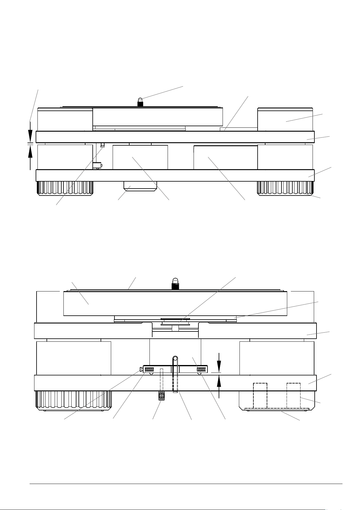
11
Motor Pulley
Spindle
Driven
Pulley
Suspension
Column
Sub-Chassis
Sub-Chassis
Main
Chassis
Main
Chassis
Feet
Isolators
Adjustable
Foot
Foot Pad Ring
Motor
Tonearm Wiring
Housing
Bearing
Spindle Base
Earth Post Dampening Bath
Height
Gauge
2mm
Height
Gauge
5mm
Motor
Counter
Balance Band
Motor
Transit
Screw
Motor Height
Adjuster (x3)
Motor Earth
Post
Tonearm
Base
SIDE VIEW L/H
Figure 4
SIDE VIEW R/H
Figure 3
12
9. UNPACKING
1. UnpackandcheckallitemsagainstthepackinglistinSecon7.
2. Having opened the packing case lid carefully li upwards the top
secon high density foam module which covers the turntable/
tonearmunit.DuetotheweightoftheModel60turntableitisbest
lied out of the caseby two people, one at each end andliing
from under the main chassis (boom of turntable) and not the
upper sub-chassis. The turntable should be sited on a substanal
tableorstrongaudiostandwhichmustbecapableofsupporngthe
turntableweightof48kg.
3. With the turntable sited li the le side of the turntable to gain
access to the motor transit screw which secures (clamps) the
motor to the main chassis. Remove the motor transit screw and the
an-fret packing strips and posion the turntable squarely and
centrally onto an audio stand. Ensure that the motor spikes are
securely inserted into the compliance cups.
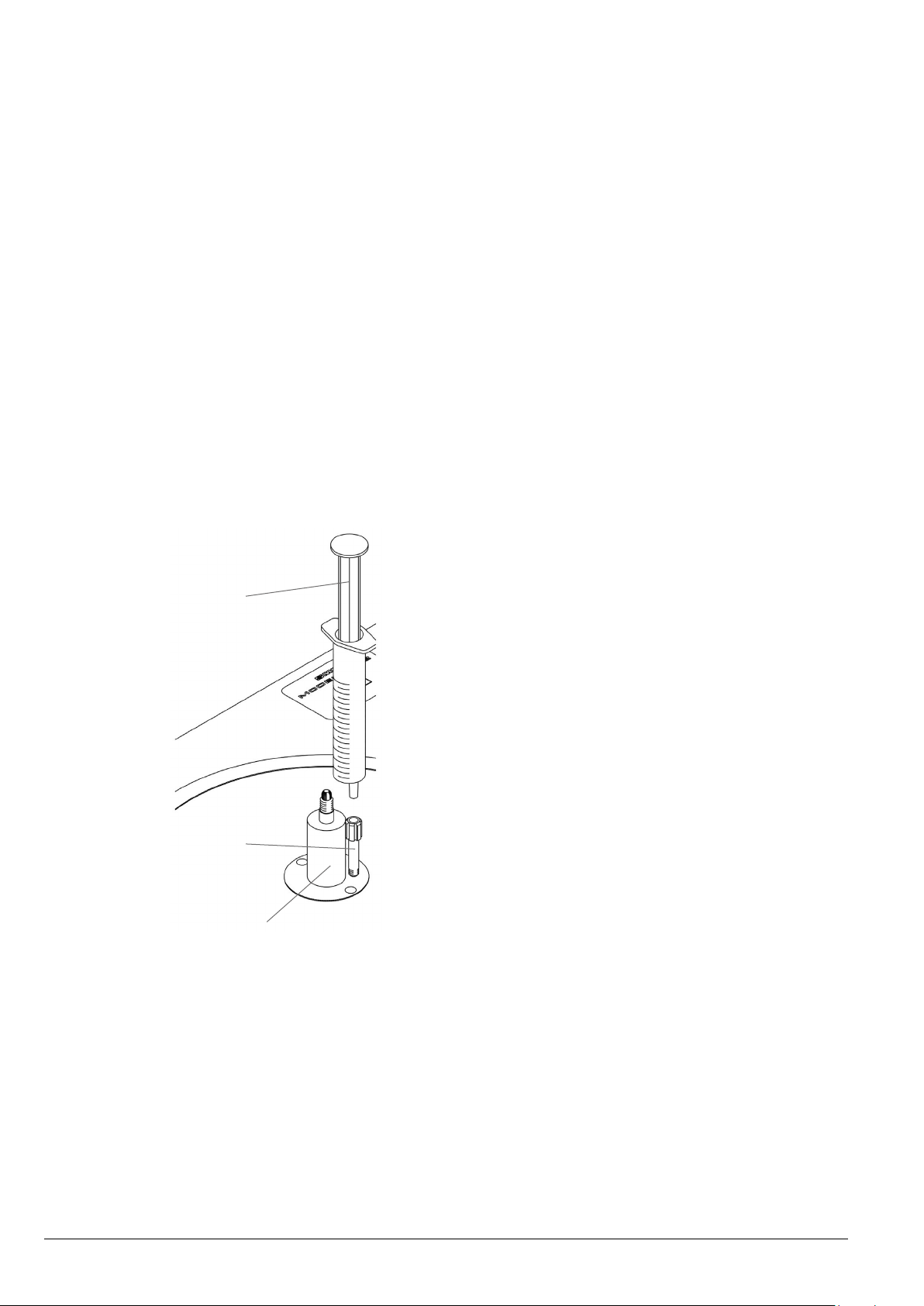
4. Theturntableisshippedwithonlya
smallquantyofoilin thebearing
housing and this should be lled
before seng up the turntable. A
measuredquantyofoilisprovided
in the syringe and needs to be
injectedintothebearinghousing.
5. Removethesyringefromitspacking
and insert the p into the oil ller
adaptor, which will be found
factory ed next to the spindle
(as illustrated).
6. Slowlyinjectthecompletequanty
of oil into the bearing housing
maintaining downward pressure
throughouttheoperaontoprevent
leakage. Remove the syringe and
disposeofitresponsibly.
7. Unscrew and remove the oil ller adaptor using the box spanner
foundinsidethetoolkit.Retaintheadaptorforpossiblefutureuse.
8. With the turntable removed and sited, proceed to remove all
ancillarycomponentsandaccessories locatedin thepackingcase
modulesbelowtheturntablepackingplaorm.
Oil Syringe
Oil Filler Adaptor
Spindle

13
10.
With the turntable unpacked and sited follow the turntable seng up
proceduresintheorderdetailedbelow:
1. Levelling the Turntable
Withtheuseofaspirit/bubblelevelensurethatthemainchassis(lower
chassis)islevelinthelateralandlongitudinalplanes.The4feetareheight
adjustableandcanbeusedtoachievealevelchassis.Whenadjusngthe
feet it is recommended to slightly li the chassis adjacent to the foot
beingadjusted.Thisaideseaseofrotaonofthefootandpreventsthe
footrubberpadbinding.
2. Levelling the Motor
a. Themotorismountedon3heightadjustmentscrews,thepointsof
whichsitincompliantcupsinthechassisbase.Fortransitpurposes
thesescrewshavebeenbackedoclearofthecompliantcups.
b. Raise the motor by adjusng the x3 height adjustment screws
(clockwise)toaheightsengof2mm,achievedbyuseofthesupplied
2mmheightgauge.Theheightgaugeisinsertedneareachadjustment
screwinturnbetweentheundersideofthemotorandthesurfaceof
thechassisbase.
c. The motor level can be checked by use of the spirit/bubble level
applied to the top surface of the motor pulley.
3. Chassis Unlocking
a. Fortransitthesub-chassis(upperchassis)islockeddownbyx4transit
screws (Secon 8 Figure 1). The transit screws should be turned
an-clockwisewiththesupplied4mmhexwrenchandremoved.The
sub-chassiswilllislowlyupwardsasthetransitscrewsareremoved.
b. Also for transit the main bearing is o-loaded by x4 pulley
transit screws. The transit screws are located in the driven pulley
(Secon8Figure1).Thesearecapvescrewsandshouldbeturned
an-clockwisewiththesupplied3mmhexhandlewrenchunlthey
stop.Ensurethehandlewrenchisfullyengagedtoavoiddamageto
the transit screw socket.
c. Withthesub-chassisunlockedcarefullyinsertthex4(5mm)suspension
height gauges between the underside of the sub-chassis and the
mid-secon of the suspension columns (Secon 8 Figure 3). With
use of the suspension adjustment key (4mm) insert the key into
the access hole on the top of each suspension column and adjust
the suspension height by turning the key clockwise to lower and
an-clockwise to raise. Adjust each column evenly unl the
sub-chassislightlycontactsall 4heightgaugesat thesameme to
ensurethesub-chassisisevenlysettoaxedheightof5mm.

14
11.
a. Placethedrivebeltoverthelargedrivenpulleyandstretchoverthe
motorpulley.Slowlyturnthedrivenpulleytoallowthedrivebeltto
takeupitsnaturalrunningposion.
b. Rotatethedrivenpulleybyhandtoensurethedrivebeltisposioned
correctlyandrotangfreely.
Removeandunpacktheplaerfromtheboomseconofthepacking
case.Placeitcarefullyandsquarelyovertheturntablespindleandlower
itgentlydownunlitrestsonthedrivenpulley,havingrstensuredthat
bothmangsurfacesareclean.
Thesuspensionheightisadjustedbyuseoftheheightadjustmentkey.
Carefullyengagethekeyintothetopcentreofeachsuspensioncolumn
andinsequenceturnan-clockwisetoraisethesuspensiontoaheight
sengof5mm(clockwisewilllowerthesuspension).Theheightsengis
checkedbycarefullyinsernga5mmheightgaugebetweentheunderside
of the sub-chassis and the mid-secon of each suspension column
(Secon8Figure3).
7. Power Unit & Speed Control Unit
Thepowerunitisconnectedtothespeedcontrolunitandturntableby
way of the connecon cables (Secon 12) with LEMO connectors. The
cablescannotbeconfusedastheycarryadierentnumberofpinswhich
arepurposelyconguredtoobservebothsafetyandmiss-idencaon.
ThecablesareidenedasAandB.
• ConneconCableA -PowerUnitOutputtoSpeedControlUnitInput
• ConneconCableB -SpeedControlUnitOutputtoTurntableInput
The AC mains power cable is connected to the power unit AC input.
A push ON/OFF switch is located on the rear of the power supply unit.
IMPORTANT
The mains voltage seng is indicated on the rear panel of the power unit.
Before ng the mains power cable check carefully that this matches your
mainsvoltage.
WARNING
Tomeetinternaonalsafetystandardsthepowersupplyunitisearthedthrough
theyellow/greenwireofthepowercableandparcularcaremustbetakento
ensurethatthisis connectedso astomaintaineecveearthing shouldthe
originalmainsplugbechanged.
TheModel60isequippedwithafactoryedSMESeriesVAtonearm.Under
no circumstancesaempttoremovethetonearmasitiswireddirectlytothe
RCA phono output sockets.
15
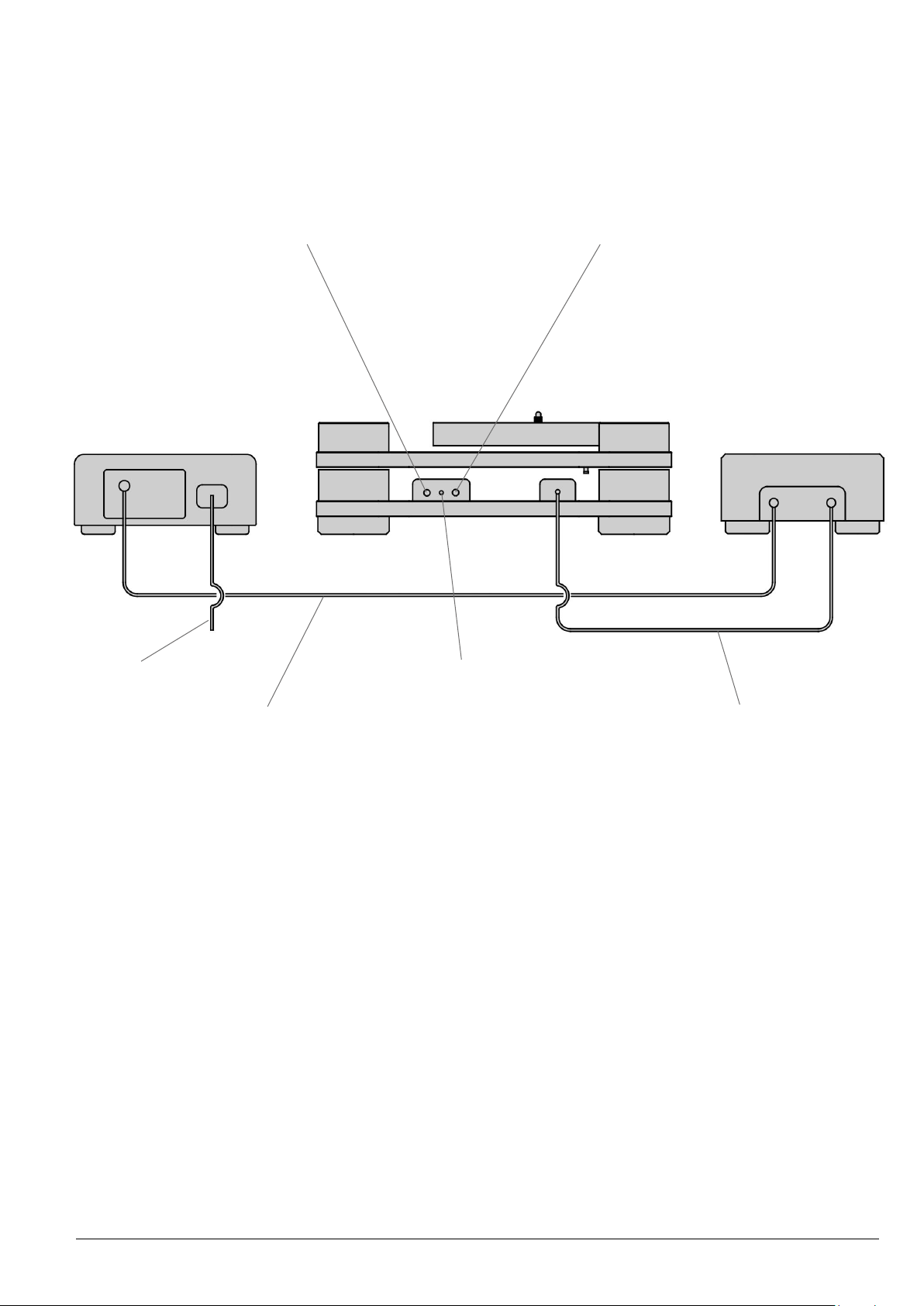
12. POWER CABLE CONNECTIONS
Right RCA Phono Output
AC Power Cable
Output
Output
Input
Input
Power Unit Speed Control Unit
Phono Ground
NOTE:
• Mains powerwhenconnecngcables.

16
13. OPERATION - Turntable
TheModel60precisionturntableispartlyrun-inbeforeleavingthefactory
butwill benetand improveaer a fewweeksof use.Do notworry if
iniallythebearingisnottotallysilent.Aslight‘swish’barelyaudibleat
verycloserangeinasilentroomwillquicklydisappearaeruseofthe
turntable.Ifyoushouldwishtocheckthespeedsengsandmakeyour
ownadjustmentstheprocedureisasfollows:
1. Mains Power:thepowerON/OFFbuonislocatedontherearof
the power unit. With power ON the last used speed indicator LED
lightwillilluminateonthespeedcontrolunitfascia.
2. Motor Power: pressing the power buon on the speed control
unitfasciawill start themotor.WithpowerOFF andpressingthe
rotarybuononthefasciathespeedsengsof331
/3and 45rpm will
cycleandbeindicatedbythespeedLED.Withthemotorrunning,
pressingthepowerbuonwillstopthemotor.
3. the stroboscopic disc installed on the plaer is
used to check speeds of 331
/3 and 45rpm. Use the strobe bands
appropriateforyourmainsACfrequency.Thediscshouldbeviewed
inauorescentorneonlight.Theappropriatebandwillsynchronise
and appear staonary when the speed is correct. Whilst forward
and reverse band movement will indicate fast or slow running
respecvely.Thisisbestobservedwiththecartridgeedandthe
tonearm in the raised posion and placed directly over the band
beingviewedasareferencepoint.
4. Speed Adjustment: with the motor running press and hold the
rotary buonfortwoseconds,the speed indicatorLEDwill begin
toash.Themotorisnowinspeedadjustmodeandthespeedcan
nowbeadjustedinconjunconwiththestroboscopicdisc.Turning
the rotary buon an-clockwise will reduce speed and clockwise
willincreasespeed.Themethodprovidesamicroneincremental
adjustment.Whenthespeedadjustmentiscompleteddepressand
release the rotary buon, the speed indicator LED light will stop
ashingandbecomeconstantandthespeedsengwillbestored
in the system memory for future use.
5. Repeatthisprocessforthe45rpmspeedrangeifrequired.

17
14. OPERATION - Playing a Record
Placetherecordspindlewasheronthespindlefollowedbytherecordand
clamp.Theclampshouldbescreweddownclockwiseenoughtodeect
therecordatintormcontactwiththeplaer.Withangerp,tapthe
recordin threeplaces equallyoveritssurfaceandwith alile pracce
it will soon become evident whether or not the record is touching the
plaer.Ifnot,somefurtherghteningoftheclampmaybenecessary.
15. MAINTENANCE
1. Therearenocricaladjustmentsorneedfor‘tweak’andonlyvery
lilemaintenanceisrequired.Cleanthedrivebeltoccasionallyby
drawing it through a piece of so ssue or linen moistened with
lighterfuel.Thesamematerialmaybeusedtocleantheperiphery
ofthemotorpulleyanddrivenpulley.Themainbearingislubricated
for life.
2. The sub-chassis (upper chassis) damping system automacally
seals when the sub-chassis is locked down and does not require
maintenance.
3. Replacethedrivebeltaer1000hoursuse.Areplacementbeltis
availabledirectlyfromSMELimited.
4. Thelifeofthesuspensionbandswilldependonclimaccondions.
If eventually they should stretch beyond further adjustment,
replacement suspension bands are available directly from SME
Limited.
5. Changing the suspension bands should only be conducted by
an experienced technician or at the supplying dealer. A technical
instruconprocesscanbeobtainedfromSMELimited.
6. Therearenouser-serviceablepartsinsidethePowerUnitorSpeed
Control Unit.

18
16. TRANSIT PRECAUTIONS
TheModel60canbesafelytransported.
SUBJECT TO THE FOLLOWING PRECAUTIONS:
Shortjourneysbycar:removetheplaer,disengagethedrivebeltfrom
themotorpulley,backothemotorheightadjustmentandretthemotor
transit screw. Lock down the sub-chassis suspension. Screw down the
fourdrivenpulleytransitscrewslightlyandevenly,justenoughtoprevent
thepulleyrotang.Theturntableitselfisbestplacedonaatoorofa
car boot/trunk. The plaer and other items can be carefully protected
and packed separately from the turntable. For all other transportaon
purposestheoriginalpackingcaseandmaterialsmustbeused.

INSTRUCTIONS
HIGH DENSITY TONEARM
This is no ordinary tonearm.
These instructions include set up procedures, adjustments and specications.
Please read carefully.

20
17. CONTENTS
Page
21 Introducon
22 Overview
23 GeneralArrangement
24 SetUp&Operaon
33 Guarantee
34 Appendix
Table of contents
Other SME Turntable manuals


