Pioneer pl-x50 User manual

(D
rrloNteerl'
STEREO
TURNTABLE
ORDER
NO.
ART-698-O
MODEL
PL.XSOCOMES
IN FIVE
VERSIONSDISTINGUISHED
ASFOLLOWS:
Thisisthe service
manuat
for model
PL-XSO/HE,HB.Forservicing
of theothertypes,
please
refer
to the
additional
seruice
manual.
@ manueld'instruction
se
refère
aumodederéglage,
enfrançais.
Este
manualdeservicio
trata
delmétodo
deajuste
escritoen
espaftol.
PICINEEFI ELECTFICINIC CCIFIPCIFIATICIN 4-1. Mesu.o 1-chome, Megu.o-ku, Tokyo 153, Jepan
U.g. PtcNEEFt ÉECTF|CI\IIGIB t:C'fIFCIFIATICTN ElS Dxfond O.rve. Moonachie. New Jensey O7O74. USA
PlCtÀlEEFl EI-ECÎF|CINIC (EUFrclPEl N.V. Luithagen-Haven 9. 2O3o AnEwetrp, Elelgts6
FfctNEEFt ELECTFlCt lleg AIJBTEIALIA PTY. LTEI. 17e-1e4 EloundêFy Road. E.êesrde. VicloFaa 3195, Ausunalia
YU O IUNE
198
I
Type Voltage Remarks
HE 22OV
and240V (Switchable) Eurooe
model
HB 22OVand240V (Switchable) U.K.
model
s110V, 120V, 22OV, 24OV (Switchable) General
exoort model
s/G '|
10V, 120V, 22OV,24OV (Switchable) U.S.
military model
KU 120Vonly U.S.A.
model
o
a
Printed
in lap,tn

CONTENTS
1. SPECIFICATIONS
2. FRONT
PANEL
FACIL
3. BLOCK
DIAGRAM
4. CIRCUIT
DESCRIPTIONS.
. .
5. MAJOR
COMPONENT
ASSEMBLY/
DISASSEMBLY
. . .
6. OPERATIONAL
DESCRIPTION,
.
. .
7. TROUBLESHOOTING
1. SPECIFICATIONS
Motor andTu
Drive
System rntable
ELECTRICAL
PARTS
LIST
. .
P.C.
BOARDS
CONNECTION
DIAGRAM
SCHEMATIC
DIAGRAM
EXPLODED
VIEWS
ADJUSTMENTS
nÉclace
AJUSTE
PACKING
Miscellaneous
Power
RequirementsAC22Ol
24OV-(switchabl 50,60H2
Power
ConsumPtion
HB
model
Dimensions 320(W)
x 98(H)
x)mm
12-5l8(W)
x3'718(H) 'l/4(D)in
Weight 2oz
Motor .DCservo
motor
Speeds
., . ' 33-1/3and45rpm
Wow
and
Flutter . . Less
than0'0457o(WRMS)
Signal-to-Noise
Ratio
. . . . More
than
70dB
(DlN'B)
(with
Pioneer
cartridge
model
PC-3MC)
Tonearm
Type Integrated
straight
pipe
arm
"C-3MCSpecifications
Type Movingcoiltype
Stylus 0.5
mil
diamond
(PN-3MC)
Output Voltage 2.5mV
(1kHz,
50mm/s
Peak
velocity,
LAT)
. 179to 2.39
(proper
29)
. .10to32,000H2
50kQ
Weight 319
Subrunctions
Fullyautomaticoperation
with separate
tonearm
motor
Automaticrecord
sizeselector
(17cm,
30cm)
Cueing
device
Built-in
anti-skatingmechanism
ITIES.
2
3
4
5
8.
9.
10.
37
39
41
43
49
51
53
55
I
11.
12.
17
22
29
Belt-drive
13.
Accessories
EP
Adaptor
Output cable
Operating
instructrons
NOTE:
Specifications and desgn subiect to possible
notice, due to tmProvements
.9W
.1
.l
1
niltnou t
Tracking
Force
.
Frequency
Response
RecommendedLoad

2. FRONT
PANELFACILITIES
O plnveecK START/sToP
swITcH(PLAY/SToPI
This
switchis
depressed
to startor stopplayback.
€) ERM ELEVATTON
SWTTCH
{ARM}
This switch is used to start playback in the middle of a recorcl
or to temporarilystopplaybackin the middle of a record
Switch depressed
I ! {up)l - raises
tonearm
Switch released I t (down)] - lowers tonearm
@ REPEAT
PLAYBAcK
sWITcH
(REPEAT
oFF/oN}
Depressing
this switch
will cause
the turntable
to playthe record
peatedly.
O sperosELEcroR
swtrcH
(spEED)
This
switch
isusedto selectturntable
speed.
Switchdepressed
(.rl - 45 rpm
Switchreleased
(f I - 33 l/3 rpm
O HEADSHELL
NOTE:
The headshetl @ and canridge @ have been drawn so that they are visibrefor
the purpoæ of expranation onty, They can not be seenas shown above during
normal operations
@ cenrnlDcE
(pc-3Mc)
@ TURNTABLE
@ CABINET DOOR
@ cENTER
sHAFT
@ RECORD
SENSING
PIN
This
sensor
functions
to
detect
whether
a
record
is
placed
on
the
platter
or not. This turntable will not c
platter. lf you attempr to start
re- on the platter, the record sensin
and hold the tonearm in place
stylus beingdamaged
by coming
plafter.
O plerteR
@ ep
ADAproR
Usethe Ep adaptorby placingit on the centershaftwhen playing backan
EPrecord.
NOTE:
Useonly thisEPadaptor with thisturntabte.
lf a different Ep adaptor is used.the stylusmay come in contaû with the Ep
adaptorandbeclamagcd.
J

4. CIRCUITDESCRIPTIONS
The circuit description is basedon the operation
of the systemwhile playing a 30cm record disc at
33 rpm.
4.1 LOADING
OUT
1. Sliding the door out causesthe power switch
S10to turn ON.
2. Pressing
the START/STOP button (switch 56)
causesthe number 13 pin of IC2 to gofrom L
to H, and this causesthe number 15 pin to go
to H. When the number 15 pin goes
to H, the
number 3 (number 8) pin of IC3 alsogoes
to
H, and the slide basedrive motor (mechanism
motor) startsrotating in a CIVdirection (caus-
ingthe tumtable to comeout).
3. As the mechanismmotor rotates,
the slidebase
travelsfrom its housedposition to its out posi-
tion. When the slide base
reaches
the record-
load position opening attachment switch 52,
the number 3 (number 8) pin of IC3 again
goes
L, stoppingthe mechanismmotor.
rc r i€840018
Fùll aulo
control
sa
æælt uo
srrch oi - oFF
'snt rwirch g!-_ or.
pr€tion sirh Ofl _ OFF
cohpt€tion sitch Ot- - OFF
TER or_ Fr
s6
s7
DOWN completion
ON
_ OFF
uP - oorN
ot - ofF
É B^;o"-r
MOTOR ORIVE
itrra.-. * l--1--.-- uP compretion 'witch
^+
T *." I -:*'i',.".n-.".,*i,"^
lll",L
tc 2 lag84027e
F
lip-f lop
Fig.4-1
Loading
out

4.4 AUTO RETURN
1. After record playback is completed and the
tonearm stylus moves from the record gxoove
into the lead out groove,the amount of move-
ment of the tonearm causesthe collector volt-
age of transistor Qb to rise. This causesthe
basevoltage of Q8 to rise, turning the transis-
tor ON (fieure 4-4).
2. When Q8 goes
ON, the number 8 and 9 pin of
IC1 goes L, and the number 10 pin goesH.
This causesthe number 9 pin of IC2 to go H,
resultingin the number 15 pin also
goingH.
3. Then, since the number 3 pin (number 8 pin)
of IC3 goes H, the mechanism motor starts
turning CW, starting the UP operation of the
tonearm.
4. Whenthe UP operation of the tonearm iscom-
pleted (rack gear pressesthe UP completion
switch SB), the number 12 pin of IC1 goes
H
causing
the number 11 pin to go L, lowering
the basevoltage of transistor 3 and turning it
OFF. SinceQ4 alsogoes
OFF, rotation of the
turntable motor is stopped.
5. After UP operation hasbeencompleted,move-
ment of the rack gear causesthe tonearm to
return to the armrest. The slide base then
s€
F€PEAÎ
moves to the OUT position and stops at the
record-load position following the sameopera-
tional procedure aslisted in item 3 of loading
out.
! END
SENSOR
CIRCUIT
1. The construction of the end sensorcircuit is
shown in figure 4-5. Whenthe tonearm reaches
a point approximately 120mm from the
center shaft, the shutter attached to the tone-
arm shaft passesbetween the lamp and Cds
sensor
blocking the light.
2. This causesthe resistancevalue of Cds sensor
to gtadually rise, boosting the collector voltage
of transistor Q5 (base potential fixed), and
generates
voltagebetween TPBand TP4. I
Sensor
adiustmenl
Fig.4-5 End
sensor
circuit
llP.o-pt"tion "*lt"h switch
S I Housd switch
S 2 An.chmont 3witch .S -
or,l
- LEE
ON - OFF
S3 UP complê1'ron lwilch ON
- OFF
54 DOWN compl€lionswltch ON
- OF-F
ss TNVERTER 6l- orr
, {"."
vet o I
'tr@
-h-
sz
aftachment switch
S5 INVERTER
sr s6 sraRT/sroP
Houæd switch 57 ARM
SA REP€AT
s4
OOwN complerion
oN- qE
o" - ggE
uP - qg!.u
oN- 9!E
rc
3 BA620a
MOTOR
ORIVE
lc 4 M8940il8
HEPEAT
CONTROL
DETECTOR
assemblv
og
Fig.
4-4Auto
return

4.2 AUTO LEAD IN
1. Pressing
the START/STOP
button (switch56)
causes
the number 18 pin of IC2 to change
from L to H. When
the number 13pin go". to
H, the number lb pin will goto L, causing
the
number2 pin of IC1 to goL.
2. The number 2 pin of IC1 going
to L causes
the
number 3 pin to go to H. This in tum causes
the number 2 pin (number Z pin) of ICB
to go
to H, and the mechanism
motor starts
rotating
_ CCW,
movingthe turntable backin slighily.
3. Also, since
the number 1b pin of IC2 isL. the
number 12 pin of ICl will go L through diode
D6. When the number 12 pin goes L, the
number 11 pin will go H, turning transistor
Q3
ON.
When the tonearm reaches the rspold disc
size (30cm) position it stops. However. the
rack gear continues moving, lowçri4g the
elevation shaft and pressing
the dowp comple_
tion switch
54.
When the down completion switdh 54 is
pressed,
the number 2 pin (number ? pin) of
IC3 goes L stopping the mechanirth
rrotor.
This
putsPL-X50in aplayback
statusil
b.
7.
1i
rl
4.
5.
O
s6
NO.
.> Âirâchment switch
I < r<
L
iwitch rl
S I Houred iwrtch
^ q- oFF
:: Arrachhenr
rw,tch ol _ ôFF
I , uP conorer,on.w,rch m_ ôTi
:: D.OW_N
cmor€tionr*,ctr ol_ ô-,
s5 TNVERTFR oi_ æf
S6 STÂRT/STOP
57 ARM
58 REPEAT
ol - oFF
I up- ôlwn
Ot r OFF
t2
ï
ot
5
s6 È!
l
^_f--\ ^ _-__{___\
_ | p_ | I )o_,1
8-----L_./ 6 _ L,-/
rlxD Èor
lC4 M88401tÊ
ÊÊPEAT
CONTROL
rc r M8840018
Full aùtocontrol
tc 2 M884o27A
GSEr 2 cLocx I
5
DETECTOR
assembry
Fig.4-2 Auto lead
in

)
4.3 ARM ELEVATION UP|DOWN
1. If the ARM button (switch 57) is pressed
during record playback (UP position), transis-
tor Ql goes
OFF. With Ql OFF, the number 7
pin of IC2 goes
L. Also, since
the number 4 of
IC2 goes
H, the number 2 pin alsogoes
H.
2. When the number 2 pin of. ICZ goes H, the
number 1 pin of IC1 also goes H, and the
number 3 pin goes
L. This causes
the number 2
pin (number 7 pin) of ICB to go L. On the
other hand, sincethe number 4 pin of IC2 is H,
the number 3 pin (number 8 pin) of IC3 also
goesH, starting the mechanismmotor to totat-
ing in a CWdirection.
3. As the meehanismmotor rotates, movement of
the rack gear rotates the driving plate, raising
the elevation shaft.
4. Then as the rack gear depresses
the UP com-
pletion switch S3, the number 4 pin of IC2
goes L, causing the number 3 pin (number 8
pin) of IC3 to also go L, stopping the mecha-
nism motor.
5. As the ARM button (switch S7) is pressed
(DO\ryN position), transistor Ql goesON, and
the number 7 pin of IC2 goes
H, and tJre
num-
ber 2 pin goesL. Since this causesthe number
1 pin of IC1 to go L, the number 3 pin goes
H.
sc
GæAT
oFF ON I
6. Whenthe number 2 pin (number 7 pin) of ICB
goes H, ttre mechanism motor turns CCW.
Operation hereafter is the sameasitem 5 and
6 in the auto lead in section until DOWN
operation is completed and playback status is
entered.
7. If the ARM button (switch S7) is placed in the
DOWN or UP position during UP or DOWN
operation, the specified DOWN or UP opera-
tion will immediately be entered.
!- it" "o-o,".,o" switch switch
S I Hoqid sith
S 2 Aechmonr lwirh ON
or-qE
ON _ OFF
oil-
S 3 UP compl.tioô tuiEh Ott - OFF
54 OOWN compldlondiçh ON - æ
55 INVERTER 6i- OrrOFF
stÀtr
/sfoP
s7
sr s6 staRT/s1op
Housedswirch s7 aRM
58 R€P€AT
s4
OOWN completion
oil - oFF
uP - q9!{ll
ON
- OFF
tc 3 8A620€
MOTOR DRIVE
rc4 Mg840ll6
REP€A1 CONTROL
Fig.4-3 Armelevation
UP|DOWN

7.
4.3 ARM ELEVATIONUP/DOWN
1. If the ARM button (switch S7) is pressed
during record playback (UP position), transis-
tor Q1 goes
OFF. With Ql OFF, thenumber
7
pin of IC2 goes
L. Also, since
the number 4 of
IC2 goes
H, thenumber
2 pin also
goes
H.
2. When the number 2 pin of IC2 goes
H, the
number 1 pin of IC1 also goes H, and the
number 3 pin goes
L. Thiscauses
thenumber
2
pin (number 7 pin) of ICB to go L. On the
other hand,since
thenumber4 pin of IC2 isH,
the number 3 pin (number 8 pin) of ICS also
goes
H, starting the mechanism
motor to rotat-
ingin a CWdirection.
3. As the mechanism
motor rotates,
movement
of
the rack gear rotates the driving plate, raising
the elevation
shaft.
4. Then as the rack geardepresses
the UP com-
pletion switch 53, the number 4 pin of IC2
goesL, causingthe number 3 pin (number 8
pin) of IC3 to also
go L, stopping
the mecha-
nism
motor.
5. As the ARM button (switch S7) is pressed
(DOWN position), transistor
Ql goes
ON, and
the number 7 pin of IC2 goes
H, andthe num-
ber 2 pin goes
L. Sincethis causes
the number
1 pin of IC1 to go L, the number 3 pin goes
H.
If the ARM button (switch S[) ir placed
in the
DOWN or UP position duririg UP or DOWN
operation, the specified DOWN or UP opera-
tion will immediately be enterbd.
Ls:
UP compl€t,on swrtch SWltch
1% ls
.41 Houseo swrtcn
i ______tÊ I
S I Hdfd Fitch Oi OFF
S ? Arl|.hruôr rw'rch Ol 6FF
5 3 UP l$tlerion swirch ;i cFF
S
4 DOIiN Ompl€tion s'r.h ON _ -
s5 r\rVEntER 6i c,
s6 srFT/tlOP
s7 ôdl
sB Fl?taÎ
ON
_ OFF
UP æWN
oil - oFF
s6 oNl
5
e3
-i-"o I .-
}j ô"** cofrpre.on
Nc + switch
lc a 8A620€
] MoToF DRIvE
.- -{---\ ^
-\--\
I p-' J p-'
B-1_-) I . I
rr|o xoR
lc 2 M8940279 ï_l
Fig.4-3
Arm
elevation
UP/DOWN

4.2 AUTO
LEAD
IN 6.
7. When the down completion switch 54 is
pressed,
the number 2 prn (number Z pin) of
IC3 goes L stopping the mechanism motor.
Thisputs PL-X50 in aplaybackstatus.
I
UP comptetion switch switch
s?
Attâchmènt switch
56
STÀRT
s7
5l
DOWN completion
5A
Rtæ^t Ê40
rc3 846208
MOTOR
DRIVE æ F-r;-r;-t
L!#L:-l lLlLlxl
trlxlsI |T-T;-Î-Ll
l"J.l*l f;-fL-f-
tHtHt(l F-f;-f-
O
rc'r
Maa+oora ii,
Full auto cootrol
tc 2 MEE4027E
Flip flop
rc4 M8840lrÊ
REPEAT
CONTROL
OETECTOR
assembtv
oa
Fig.4-2 Auto lead
in

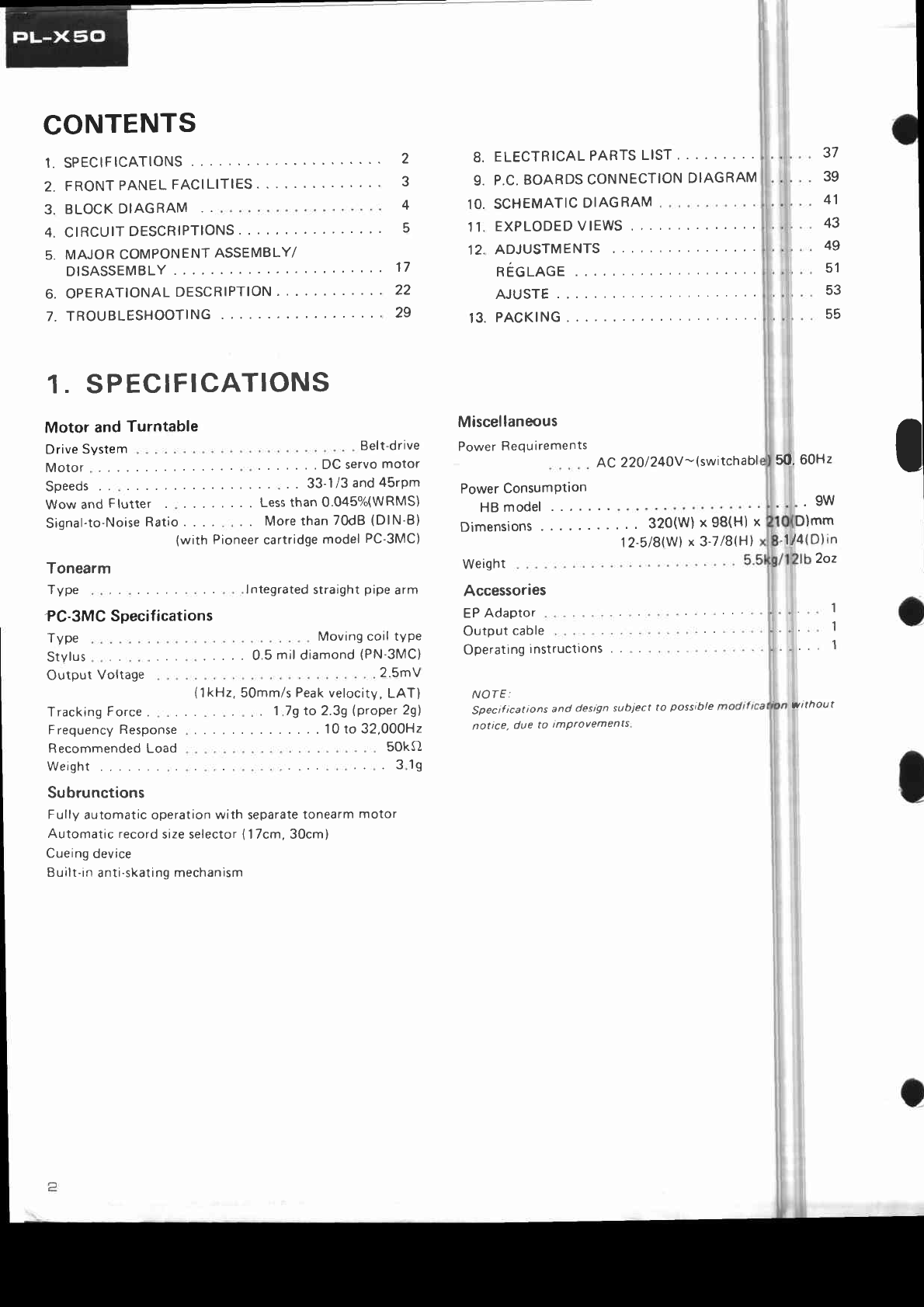
3. This signal passes
through D10 (peak hold
diode), and is applied to the differential cir-
cuit consisting
of C7, R30, and R31. This dif-
ferential circuit servesto convert the tonearm
position signalinto a speed
signal.
o Peakhold diode
Sewes to prevent misoperation due to ec-
centricity in the recorddisc.
4. As the tonearm stylus moves into the record
disc lead-out groove, its movement becomes
faster, and when the potential at point A rises
above approxfmately 0.6V, Q8 comes ON,
dropping the potential of the collector side.
This senresas an end sensorsignal sending the
number 8 and 9 pin of IC1 L.
5. When the tonearm is UP, transistorQ6 andQ7
prevent transistor Q8 from turning ON.
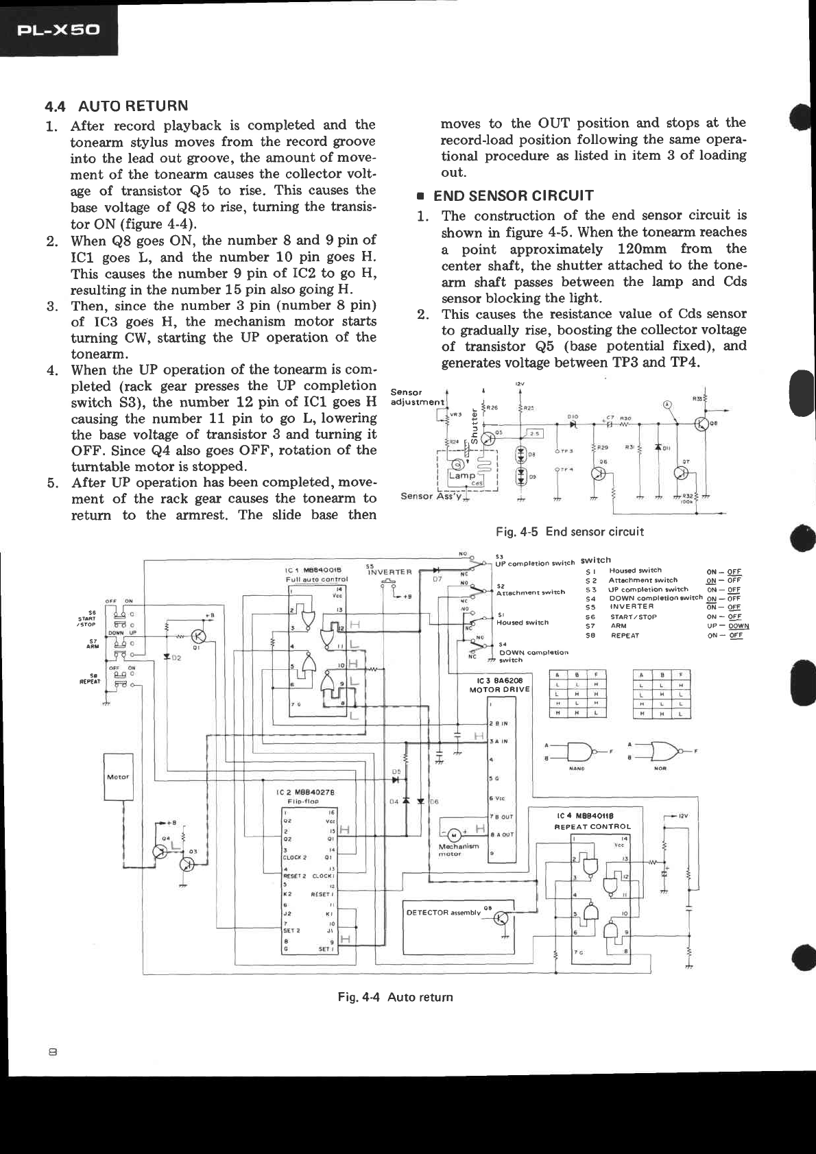
4.5 AUTO STOP
1. When the START/STOP button (switch 56)
is pressed
during record playback, the number
13 pin of.
IC2 goes
from L to H, and the num-
ber15pin goes
H.
2. Whenthe number 15 pin goes
H, the number 3
pin (number 8 pin) of IC3 also
goes
H, starting
the mechanism motor in the CW direction and
rcr ra8400tg
Full ruro control
940
arm returns to the armrest fing the opera-
enteringUP operations.
After UP operations are
tions listed in items 4 and
section,and the slide base
loadposition.
. ill "*o,",,o..*,tch twitch
3. . the tone-
e auto return
at the record-
Str)
in theUP
OFF
status,
r L. and the
mfter 1 pin of
mber 3 pin is
igtal input to
H, thereby
ber 2 pin
. the mecha-
turn CCW.
Pbut-
t{e ON posi-
15pin
pfn will go L
c$anging the
ber 2 pin
to L.
5!
INVERTER
it*n-.'r,*,..n it uP
on _ oFF
Irch ot _ oFF
rw,rch oil - oFF
Sl
OOWN complstioô
sirn ot _ oFF
oi - of,F
ot - oFF
uP - qg!-\
ON
_ OFF
rc 3 846206
MOTOR
DRIV€
âI
3
f_l
:
€
With the ARM button (
position and transistor Q1 in
the number 7 pin of IC2
number 2 pin is H, and the
IC1 is H. tn this status.the
held L no matter whether the
the number 2 pin of IC1 is
making it impossible for the
(number7 pin) of IC3 to go
nism motor therefore
At this point, when the ST
ton (switch 56) is switched
tion and the number 13 and
of IC2 goes
H, the number 1
turning transistor Ql ON
number 7 pin of IC2 to H,
to L, andthe number 1 pin
rc 2 M80aoa78
rc
4 H88401!8
REPEATCONT
Fig.
4-6 Autostop

4.O AUTO REFEAT
1. When the REPEAT button (switch S8) is
pressed, switch S7 goes to the ON position,
and the number 8 pin of IC4 is opened to L,
making it the same
logic level aspin number 3.
2. With switch 58 in the ON position (auto repeat
status), operating auto return causesthe end
sensor circuit (transistor Q8) to come ON,
and the number 1 pin of lCA to go L. The num-
ber 3 pin and number 8 pin go H (in auto
return, when the number 15 pin of IC2 is H,
the number 6 pin of.IC4 is H. Whenthe num-
ber 3 pin is L, the number 1 and number 2
pin areL, and the number 3 pin isH).
3. After the tonearm has completed lead-out and
returned to the armrest, the slide base moves,
opening attachment switch 52, and the number
9 pin of IC4 is held H for the duration of the
charging of capacitor C6. This causesthe num-
ber 10 and number 12 pin to momentarily go
L.
4. lVhen the number 11 pin of IC4 goesH, and
the number 12 pin of.IC2 goes
H, the number
15 pin will go L to execute lead-in. Operations
thereafter arethe same
asauto lead-in.
s3
ftæ^1
lVhenthe START/STOP button (switch 56)
is pressedplacing the unit in an auto stop
status, the repeat status cannot be entered
even though the REPEAT button (switch
58) isdepressed.
lI "o-pt.tion "*it"h switch oil - oFF
I
s 2 Attrchment 3wttch oN_ oFF
i2ttacn-ent switcr' s 3 uP compl€lion lwircn ii - Sqf- 54 DOWN comptêtton.witch Oit
_ -OFF
55 INVERTER d- Orr
s6
S'AR'
s7
s' s6 sraRT/sTop
Housed
swatch 57 ARM
SA REPEAT
s4
OOWN compl6tion
uP- qgtgll
ON - OFF
r;-T-;-F] r;-ft-r-
|Ï-T1-ril r;-T;-T;]
FT. I l-rT,T l
lHlLltst lHlLlrl
lHtËlrl lHlHlLl
rcI lrEE4OOrg 1trua"ta"
rc
3 446208
MOTOROÊIVE
rs
ol
ol
t3
cLocxl
t2
iEs€l I
to
9
*ll
tc 4 M8B40llE
FEPEAl CONTROL
DETECTOR assembly
Fig.4-7 Auto repeat

4.9 TIMING
CHART
1
(REPEAT
SWITCHOFF)
Mechanism
motor
Turntable
motor
Auto function
End
sensing
Housed
switch
S1
Record-load
switch
S2
UP
completion
switch
53
DOWNcompletion
switch
54
ControlFF
ARM
switch
57
EVFF
Inverting
switch
55
Notes:
o S/S indicatespressingthe START/STOP butron
o Indicates the direction of rotation of the mechanism
motor
r Sl - 34 ind.icates
thedirection of sutitch
connection
r .F.F
shou.rswhether the H signal isfrom e or @.
t Auto function indicates
theoutput status.
o Loading out and other operational status areshown in
Figure4-10.
POWER
,. oN
doused I
posr
1r
on Loôdrng out
a : Loading
out
b : Loading
in
c : Lead-in
d: Lead-out
Turntable
olattgi
recron) Stop
FiS.4-10
Turntable
posit

Play I Load-out
Record-load
Posrtron Loadingout Record.load
poSrûon
Loading
in
I
s/s

1.
2.
4.7 LOADING
IN
e40
lcI Mga4ooiE ltrua ^ra "
Full auto cont.ol
UPcompletion
sw'rch Switch
When the START/STOp button (switch 56)
is pressed
while the unit is at the record-load
position (throwing switch 56 to the ON side),
the number 13pin of IC2 changes
from L to H.
When the number 18 pin of.IC2 goes
to H, the
number 15 pin goes
to L, the number 1 and2
pin of ICl goes
to L, and the B pin goes
to H.
The_number
2 pin (number ? pin) of ICBgoes
to H, startingthe mechanism
motor to rotating
CCW.
Sincethe number 12 pin of IC1 goes
L, the
number 11pin goes
H, andtransistor
e3 and
Q4 turn ON for turntable motor rotation_
1S I Housd
s2 A
s2
Artachm€nt switch s3 uPc
rc
3 8Â6208
MOTOR
DRIVE
5l
OOWN comptsrion
s4 00wN
S5 INVER
56 START/
57 ÂRM
S8 REP€AT
rc
4 M884Ofi8
REPEAT
CONTROL
ot{ - oFF
h on-ôFF
rh or-Fi
sirch il_ otr
off - oFF
DETECTOR
assembtv
oa
Fig.
4-8 Loading
in

4.8 RECORD
DISC
PROTECTION
SWITCH
Switch S5senres
to guard againstthis'
2. ïtlhen the rccord disc is pressingswitch S5,the
number 9 and number 15 pin of lC2 are held
H. This causesthe number 3 pin (number 8
pin) of IC3 to remain H, causing the mecha-
nism motor to rotate CW'
irT compterio^ s-it h Switch
I
e
I
s2
Atâchment swilcn
s'
SA REPEAT
5a
DOWN cpmpletaon
S I Housed siæh Oil - gi
S 2 Arschment .wich -9! - OFF
s 3 UP completion siEh ON- OÉF
54 OOWN compl.donslsh Ol! -
oil-gE
oN- ggE
56
sl rl
/st@
s7
oN
- oJE
uP
- !94-s
ON
_ gEE
OFF ON
e40 l lE lrj l' I'l' I
l-r+'+] l#l
I r I H I H I t_!__l_-Ll____
L1 lLl'l l"l'l'l
lH lH lt I lH lH lt I
fcI i6B4oors tt*ur"rr. a-È--Té
rc
5 8A62@
MOTOR
DRIVE
tc 2 MO84()278
F
liP-flop rc 4 Mgg40ll8
REPEAT CONTROL
FiS.
4-9 Record
disc
protection
switch

5. MAJOR COMPONENT
ASSEMBLY/DTSASSE
*&--

I
1.
2.
Depressthe START/STOP button to bring the
turntable unit out, and unplug the line cord
from the receptacle.
Remove the bonnet case(hood) by loosening
screwQ. ç-oQ
Fig.
5-2 Bonnet
case
remove
The escutcheon cover is inserted in the base
of
the main unit. First, pull out on the front side
of the escutcheon cover and remove the front
panel.
Wiring from the transformer, tonearm, and
auto function is located on the rear sideof the
escutcheon cover. Remove these wires by
desoldering. Also remove the end sensor con-
nector (Figure 5-3).
Fig.
5-3 Escutcheon
coverremoval
in the rear. Opening and closing of the front
panel turns the power switch ON/OFF. To
set the po\Merswitch, after the front panel
has been attached, with the panel closed,
place your thumb over the pivot of the
power switch lever, and while applying pres-
sure rotate the lever toward the microswitch
(in the direction of the anow) until a click
is heard. This operation is performed with
the slide basein the housedposition (Figure
5-4).
Power
switch
(Microswitch)
t panel
switchlever
Fig.5-4 Power
switchattachment
5. When the escutcheon cover is removed for
operational checks,etc., disconnecting
the end
sensor connector and bringing it out to the
front of the escutcheoncover and then rotating
it 180 degrees to the rear of the unit will
make the check easier.
Note:
Since opening and closing of the front panel of PL-X50
turns the pouer switch ON/OFF (through the power
switch lever), alwalts place the power switch to the ON
position for operational chechs. (Use a screwdriver to
depress the microswitch actuator. )
I
3.
4.
,*,-StiOe base
cover
Slidebase
Soldering
iron
Transformer
wiring
Fig.5-5 Slide
base
remove

Completion Record'loaci
Loading oul position
Loadingin Loadrngin Housed
position
i
(End
sensing
Iexecuted)

4.1O TIMINGCHART
2 (REPEAT
SWITCH
ON)
Mechanism
motor
Turntable
motor
Auto function
Endsensing
Housed
switch
Sl
Record-load
switch52
UPcompletion
switch
53
DOWN
completion
switch
54
Control FF
ARM switch57
EVFF
Inverting
switch
55
POWÉR
ON flgs6ld-load
position

6.
7.
The slide base
cover is held by hooks in the
slide base. The front section is secured by
screwsin two places.
The screws
are loosened
asshownin Figure 5-5,andthe slidebase
cover
is lifted up from the forward side of the slide
base while holding the platter to prevent it
from comingoff.
The turntable is not easily separated from its
bearing assembly with the PL-X50. For re-
moval,the slidebase
must bein the recordload
position (record disc loading position), ild
screvy
@ removed from the bottom sideof the
slide rail. The bearing assembly and platter
wilI come off together. Sincethe drive belt is
still attached to the platter, be careful not to
damage
the belt.
Slide
rail
Screwdriver
Fig.
5-6 Turntable
platter
remove
ATTACHINGTHE
TURNTABLE
PLATTER
(WITH
BEARINGASSEMBLY)
Place
the unit on the slide
rail andinsertthe
bearing assemblyin the opening in the cen-
ter of the slide base.Lightly secure
screw@
from the bottom sideof the sliderail. Then
with a small screwdriver inserted between
the turntable platter and the slide rail,
gently tap the projection on the outer cir-
cumferenceof the attachment flange while
Turntable
platter
Slide
base
Screwdriver
rotating the bearing assembfiy.
(This is to i
seatthe projection in the slot to preventthe
bearing assemblyfrom rotadng.) After the
bearing assembly is firmly sèabd and will
not rotate, securely tighten Bcrtw 2 on the
bottom of the slide rail (Fi$rre 5-7). After
the turntable platter (bearing assembly) is
i secured,
replace
th. Olr:_!"tt, __
8. The slide base can be removed by loosening
screw@(Figure
5-8).
;Screw@
Slidebase
Fig. 5-8 Slide
base
remoye
I SLIDEBASEATTACHMENT I
i Position
the sliderail approf,irnately
20mm
inward from the record-load position, and
line the slide baseup with thô positioning
hole of the sliderail. At thig tinre, the lock
, lever assembly should be attached, but
disengaged
from the rack (the lock Iever
assembly is pressedtoward the slide base
side by the lock lever reset pNâte)(Figure
5-9). Now, manually rotate the slide base
drive motor pulley CCWto Ftrun the slide
base to its record-load paitlon. Finally,
set the record-load detectlon plate and
i record-load detection reset plate to the
i recordJoad
setting
(Figure
5-1.0).
t-
L. -- - - '..=//
Fig.
5-9Slide
baseattachnËnt1
Slide
rail
position
ing
Fig.
5-7 Turntable
platter
attachment
Other manuals for pl-x50
1
Other Pioneer Turntable manuals

Pioneer
Pioneer PL-A45 User manual

Pioneer
Pioneer PL-J2500 User manual

Pioneer
Pioneer PL-550 User manual

Pioneer
Pioneer PL-550 User manual

Pioneer
Pioneer PZ-115D User manual

Pioneer
Pioneer PL-12D User manual

Pioneer
Pioneer PL-200Z User manual

Pioneer
Pioneer PL-510A User manual

Pioneer
Pioneer PL-Z93 User manual

Pioneer
Pioneer DEH-P7550MP User manual

Pioneer
Pioneer PL-560 User manual

Pioneer
Pioneer PL-55DX User manual

Pioneer
Pioneer PL-530 User manual

Pioneer
Pioneer PL-430 WE User manual

Pioneer
Pioneer PLX-1000 User manual

Pioneer
Pioneer PL-600 User manual

Pioneer
Pioneer pl-510 KLT User manual

Pioneer
Pioneer PL-L1000 User manual

Pioneer
Pioneer PL-41A User manual

Pioneer
Pioneer CLD-1600 User manual