SME 15 User manual

INSTRUCTIONS
MODEL 15

SME is an iconic brand founded in 1946 by audio legend Alastair
Robertson-Aikman in West Sussex, England. Today SME is
recognised as makers of the nest precision turntables
and
tonearms in the world. Entirely made in-house with state of
the art manufacturing processes, complemented by traditional
craftsmanship methods.
SME audio has evolved from 75 years of engineering excellence,
innovation and perfection delivering precise and pure audio
reproduction
.
Audio Perfection

INSTRUCTIONS
This is no ordinary turntable.
These instructions cover unpacking, set up, specications and operation.
Please read carefully.
MODEL 15
PRECISION TURNTABLE

CAUTION: RISK OF ELECTRIC SHOCK DO NOT REMOVE POWER UNIT COVERS.
CAUTION: TO REDUCE THE RISK OF ELECTRIC SHOCK, DO NOT REMOVE THE POWER UNIT OR SPEED CONTROL UNIT
COVER. THERE ARE NO USER SERVICEABLE PARTS INSIDE. REFER ALL SERVICING TO QUALIFIED PERSONNEL.
• Please read this manual carefully and keep it in a safe place for future reference.
• TheventslotsintheSpeedControlUnitarefornecessaryvenlaon.Toensurereliableoperaonofthisapparatusandtoprotect
fromoverheangtheseventsmustneverbeblockedorcovered.
• Donotplaceawatercontainingvesselonthisapparatus,asthiscanresultinariskofreorelectricshock.Donotexposethis
apparatus to rain or place it near water.
• Ifthisapparatusaccidentallygetswet,unplugitandcontactanauthoriseddealerimmediately.
• Youcancleanthisapparatuswithadampclothwhennecessary,butbesuretounplugtheapparatusrst.Tocutothepower
source,unplugtheapparatusfromtheACwalloutlet.
• DonotoverloadACwalloutlets,powercablesoradaptorsbeyondtheircapacityasthiscanresultinreorelectricshock.
• Powercablesshouldberoutedsothattheyarenotlikelytobewalkedonorpinchedbyitemsplaceduponoragainstthem,paying
parcularaenontocablesattheplugend,adaptorsandthepointtheyexitfromtheappliance.
• BeforeconnecngtheACpowercabletothePowerUnit,makesurethevoltageofthePowerUnit,asmarkedontheidencaon
labelattherear,correspondstothelocalelectricitysupply.
• Neverinsertanythingmetallicintotheopenpartsofthisapparatus.
• OnlyaqualiedtechnicianshouldremovethePowerUnitorSpeedControlUnitcover.
• Besuretoholdtheplug,notthepowercable,whendisconnecngthisapparatusfromanelectricsocket.
• LocatethisapparatusnearaneasilyaccessibleACoutlet.
• If this apparatus does not operate normally, in parcular if there are any unusual sounds or smells, unplug it immediately
and consult an authorised dealer.
• UnplugthisapparatusfromtheACoutletbeforeanyservice.
IMPORTANT NOTICE:
ThepowercableonthisequipmentwhensuppliedforuseintheUK,isedwithamouldedplugincorporangafuse.Thevalueof
thefuseisindicatedonthepinfaceoftheplugandifitrequiredreplacingafuseapprovedtoBSI1362ofthesamerangmustbe
used.Neverusetheplugwiththefusecoveromiedifthecoverisdetachable.Iftheplugedisnotsuitableforthepowerpointsin
yourroomorifthepowercableisnotlongenoughtoreachthepowerpoint,youshouldobtainasuitablesafetyapprovedextension
lead or consult your dealer for assistance.
IMPORTANT:
Thewiresinthepowercablearecolouredinaccordancewiththefollowingcode:BLUE NEUTRAL, BROWN LIVE. As these colours may
notcorrespondtothecolouredmarkingsidenfyingtheterminalsinyourplug,proceedasfollows:ThewirecolouredBLUEmustbe
connectedtotheterminalmarkedwiththeleerNorcolouredBLUEorBLACK.ThewirecolouredBROWNmustbeconnectedtothe
terminalmarkedwiththeleerLorcolouredBROWNorRED.
WARNING:
DO NOT CONNECT EITHER WIRE TO THE EARTH TERMINAL, WHICH IS MARKED WITH THE LETTER (E) OR BY THE EARTH SYMBOL
OR COLOURED GREEN OR GREEN/YELLOW.
WEEE SYMBOL INFORMATION
Correct Disposal of This Product (Waste Electrical & Electronic Equipment)
(Applicable to the European Union and other European countries with separate collecon system).
Themarkingshownonthisproductoritsliterature,indicatesthatitshouldnotbedisposedwithotherhouseholdwastesatthe
endofitsworkinglife.Topreventpossibledamagetotheenvironmentorhumanhealthfromuncontrolledwastedisposal,please
separatethisfromothertypesofwastesandrecycleitresponsiblytopromotethesustainablere-useofmaterialresources.
Householdusersshouldcontacteithertheretailerwheretheypurchasedthisproductortheirlocalgovernmentoce,formore
detailedinformaonofwhereandhowtheycantakethisitemforenvironmentallysaferecycling.
Businessusersshouldcontacttheirsupplierandcheckthetermsandcondionsofthepurchasecontract.Thisproductshouldnot
bemixedwithothercommercialwastesfordisposal.
4

5
1. CONTENTS
Page
6 Introducon
7 Dimensions&Weights
7 Drive System
7 SpeedRange
8 PackingList
9 PartsIdencaon-Turntable
11 Unpacking
13 SengUp-Turntable
15 SengUp-Tonearm
16 PowerCableConnecons
17 Operaon-Turntable
18 Operaon-PlayingaRecord
18 Operaon-Tonearm
19 Maintenance
20 TransitPrecauons
21 Guarantee
22 Appendix

6
2. INTRODUCTION
The SME Model 15 precision turntable is built to exacng engineering
standards providing reliability and freedom from crical adjustments.
Buildintegrity,sophiscatedelectronicsandvibraonfreemovingparts
allowthefullcapabiliesofanysoundtobefullyexplored.

7
3. DIMENSIONS & WEIGHTS
Turntable mm (inch)
Width 452(17.80)
Depth 361(14.21)
Height(topoftonearm) 175(6.88)
Speed Control Unit
Width 150(5.90)
Depth 295(11.61)
Height 85(3.34)
Power Unit
Height 83(3.26)
Width 190(7.48)
Depth 243(9.56)
330(12.99)
Weight kg (Ib)
Turntable 18.73(41.29)
PowerUnit 4.04(8.90)
SpeedControlUnit 2.52(5.55)
Shipping 29.1(64.15)
4. DRIVE SYSTEM
The turntable is driven by a custom made bi-phase AC synchronous
motor.ThespeedcontrolunitusesadedicatedDSPenginetogenerate
two independent pure mathemacal sine waves which provide total
controloffrequency,phaserelaonshipandamplitude.Theseinturnare
matched (tuned) to the motor for accuracy to obtain the best possible
performance. The output driver stage is a 2 channel, class AB Bi-polar
designwith lowdistoronandrelaycoupleddirectlytothe motor.The
enredesignisimplementedusinghighqualitysurfacemounttechnology
onagoldplatedFR4PCB.
5. SPEED RANGE
Thespeedrangeis331
/3and45rpmwithindependentmemorysengsvia
a switched encoder.

8
6. PACKING LIST
Qty Descripon 3
1 Model15Turntable..............Tonearm..............
1 SpeedControlUnit
1 PowerUnit–100V 115V 230V
1 PowerCable–UK EU USA
1 LEMOPowerCables
1 DriveBelt
1 SyringeofBearingOil
1 Plaer
1 StroboscopicDisc
1 OilFillerAdaptor(ed)
1 OilFillerBoxSpanner
1 RecordClamp
1 RecordSpindleWasher
1 SuspensionHeightSengGauge
1 StylusGuard
4 M3x12CapScrews(ed)
1 3mmHexHandleWrench
1 4mmHexWrench
1 TonearmToolKit
1 GuaranteeCard
1 TonearmInstruconManual
1 Model15InstruconManual

9
7.
Upper Gallery
Cover Driven Pulley Drive Belt
Turntable
Spindle
Record
Spindle
Washer
Plaer M3x12
Cap Screws
Suspension
Bands
Lower Gallery
Cover
Sub-Chassis
Motor
AdjustableFeet
(x3) Motor
Transit
Screw
Dampening
Bath
Insert
Stylus
Guard
Centralising
Band
Rubber
Insert Pad
Stainless
Steel Ball
Main
Chassis
Height
Seng
Gauage
Column
Base
Motor
Pulley
Pulley Transit
Screws(x4)
SuspensionAdjustment
Point-3mmHexWrench
Suspension Transit Screws
(x2)
TonearmMounngPlate
JackingScrews

10
7.
2
3
4567
9
10
11
12
5
6
8
1
23
1
4
1. SpeedControlUnit
2. PowerBuon
3. RotarySpeedControl
4. Air Vents
5. Plaer
6. RecordClamp
7. Tonearm
8. Headshell
9. Stylus Guard
10. SubChassis
11. MainChassis
12. AdjustableFoot
1. SpeedControlUnitInput
2. LeRCAPhonoOutput
3. EarthPost-Turntable
4. RightRCAPhonoOutput
5. Motor
6. EarthPost-Motor

11
8. UNPACKING
1. UnpackandcheckallitemsagainstthepackinglistonPage8.
2. Theturntableshouldbeplacedonasubstanaltableorstrongaudio
stand,thisshouldbeinitsnalposionforsengup,asmovement
aerthisprocedureisbestavoided.
3. The adjustable feet allow for two methods of interface with the
mounngsurface.
a)Asreceivedonrubberinsertpadssetintotheundersideofthe
feet.
b)Stainlesssteelballsalsosetintotheundersideofthefeet.
WARNING:
Method (b) is not suitable for delicate surfaces as indentaon
damagemaybecaused.
4. Ifhardmounngtheturntableonthestainlesssteelballsispreferred,
proceed as follows:
a)Posionthebasesothatoneofthesupporngfeetoverhangs
thetablebyabout10cms,unscrewandremovethatfoot.
b)Removetherubberpadfromthefootbypushingoutthroughthe
smallholeontheuppersideofthefootusingthelongerlegof
the2mmhexwrench.
c)Replace the supporng foot and repeat the procedure for the
other two feet.
5. Lithemotorsideoftheturntableandremovethemotortransit
screwfromtheundersideofthemainchassis(immediatelybelow
themotor).Removethetwopackingstripsfrombeneaththemotor
andrelocatethethreemotorbasepostsintotherubbercompliance
cups.
6. The turntable is packed with only a small quanty of oil in the
bearing housing and this should now be lled. A metered charge
(syringe)ofbearingoilisprovided.

12
8. UNPACKING
7. Removethesyringefromitspackagingandinsertthesyringepinto
theoillleradaptor,whichwillbefoundalreadyedtonearthe
spindle(asillustrated).
8. Slowlyinjectthecompletequantyofoilintothebearinghousing
maintaining downward pressure throughout the operaon to
preventleakage.
9. Removethesyringeanddisposeofitresponsibly.
10. Unscrew and remove the oil ller adaptor using the box spanner
tool.Retaintheadaptorforpossiblefutureuse.
Oil Syringe
Oil Filler Adaptor
Spindle

13
9.
1. Levelling
Withtheuseofaspirit/bubblelevelensurethatthemainchassis(lower
chassis)islevelinthelateralandlongitudinalplanes.The3feetareheight
adjustableandcanbeusedtoachievealevelchassis.Whenadjusngthe
feet it is recommended to slightly li the chassis adjacent to the foot
beingadjusted.Thisaideseaseofrotaonofthefootandpreventsthe
footrubberpadbinding.
2. Transit Locks
Fortransitthesuspensionislocked(secured)bytwoscrews;theseare
accessiblethroughholesinthedrivenpulley.Thetransitscrewsshouldbe
turnedan-clockwisewiththesupplied4mmhexwrenchandremoved.
Themainbearingiso-loadedbyfourpulleytransitscrews.Theseare
capveand shouldbe turnedan-clockwisewith the3mm ball-ended
hexwrenchunltheystop.Ensurethewrenchisfullyengagedtoavoid
damagetothetransitscrewsocket(seepage9,transitscrews).
3. Drive Belt
Placethedrivebeltoverthelargedrivenpulleydownasfarasthepulley
ange, ensuring that it is free from twists and stretch over the motor
pulley. The pulleys will be out of alignment without the weight of the
plaersorotaonmustnottakeplaceunltheplaerhasbeened.
Unpacktheplaerandplaceitcarefullyandsquarelyovertheturntable
spindleloweringitgentlydownunlitrestsonthedrivenpulley,having
rst ensured that both mang surfaces are clean. Rotate the plaer
slowlybyhandtoposionthebeltonthepulleys.
WARNING:
The unique damping material (isodamp) installed on the plaer top
surfacehasbeendiamondturnedandscrolledforinmatecontactwith
therecord.Avoidhandlingtheisodampmaterialandtreatitlikeavinyl
recordasitcouldbeeasilydamaged.
5. Suspension
The sub-chassis suspension system is set to the operang height by
way of inserng the 3mm hex wrench into the centre hole of each
uppergallerycoverandrotangclockwisetoraisethesub-chassis.The
operang height is correct when a 3.5mm clearance (gap) is achieved
betweenthesub-chassisandcolumnbaseasindicatedonpage9.The
3.5mmclearanceismeasuredbyuseoftheheightsenggauge.An-
clockwiserotaonofthe3mmhexwrenchwilllowerthesub-chassis.
Aer seng the suspension height hold the sub-chassis fully down
and then release it. Check and re-adjust as needed, nong that new
suspensionbandstakealilewhiletoseledown.
Asinglebandarrangedhorizontallybeneaththesub-chassiscentralises
thesub-chassisagainsttheopposingpullofthedrivebelt.

14
9.
Ifitisdesiredtoincreasesub-chassisisolaonbecauseofunusuallyclose
proximitytothespeakerstherecommendedsuspensionheightclearance
of 3.5mm can be reduced to 2mm. This lowers the spindle/bearing
housingdeeperintothedampeningbathandsubsequentlyincreasesthe
dampeningacon.
6. Power Unit & Speed Control Unit
Thepowerunitisconnectedtothespeedcontrolunitandturntableby
wayofthe conneconcables(Secon16)withLEMO connectors. The
cablescannotbeconfusedastheycarryadierentnumberofpinswhich
arepurposelyconguredtoobservebothsafetyandmiss-idencaon.
ThecablesareidenedasAandB.
1. ConneconCableA-PowerUnitOutputtoSpeedControlUnitInput
2. ConneconCableB-SpeedControlUnitOutputtoTurntableInput
The AC mains power cable is connected to the power unit AC input.
A push ON/OFF switch is located on the rear of the power supply unit.
IMPORTANT
Themainsvoltagesengisindicatedontherearpanelofthepowerunit.
Beforengthe mainspowercable checkcarefullythatthismatches
yourmainsvoltage.

15
10. SETTING UP - TONEARM
The Model 15 is equipped with a mounng base for SME tonearms,
Model309,SeriesIVandSeriesV.
The tonearm manual provides installaon, set up and operaon
informaon, including cartridge installaon. Before ng the tonearm
ensure that the four socket cap screws holding the tonearm mounng
plate tothesub-chassisareght.Thetonearmshould nowbesecured
tothemounngplateusingthefourM3x12mmcapscrews.Rotatethe
output socket on the underside of the tonearm and connect to the audio
cableextendingfromthemainchassis.
The tonearm mounng plate is ed with jacking screws to facilitate
removalfromthesub-chassis.Theyshouldbeturnedclockwise,alternately
insmallincrementsunltheplatecanbeliedo.The2mmhexwrench
is provided for this purpose.
16
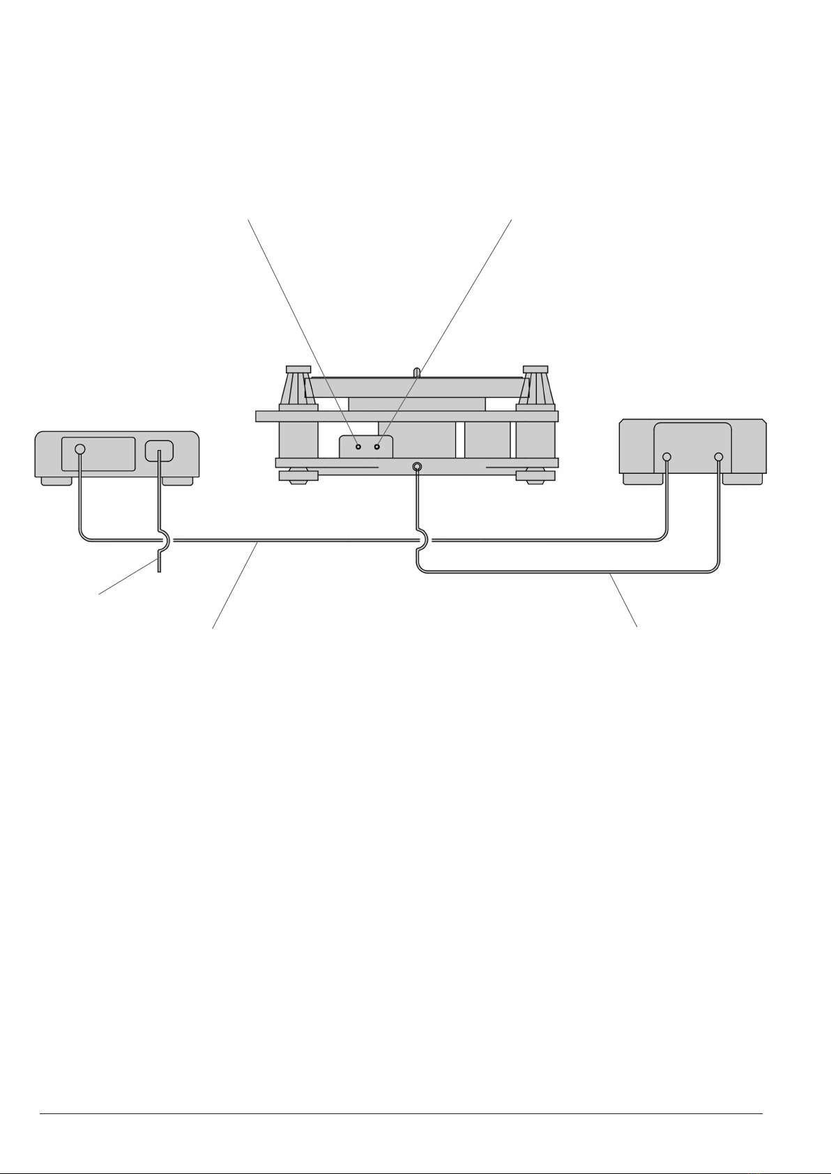
11. POWER CABLE CONNECTIONS
Right RCA Phono Output
AC Power Cable
Output
Output
Input
Power Unit Speed Control Unit
NOTE:
Mains power whenconnecnganddisconnecngCablesAandB.

17
12. OPERATION - TURNTABLE
TheModel15precisionturntableispartlyrun-inbeforeleavingthefactory
but will benet and improve aer a few weeks of use. Do not worry if
iniallythebearingisnottotallysilent.Aslight‘swish’barelyaudibleat
verycloserangeinasilentroomwillquicklydisappearaeruseofthe
turntable.Ifyoushouldwishtocheckthespeedsengsandmakeyour
ownadjustmentstheprocedureisasfollows:
1. Mains Power:thepowerON/OFFbuonislocatedontherearof
the power unit. With power ON the last used speed indicator LED
lightwillilluminateonthespeedcontrolunitfascia.
2. Motor Power: pressing the power buon on the speed control
unitfasciawillstartthemotor.With powerOFF and pressingthe
rotarybuononthefasciathespeedsengsof331
/3and 45rpm will
cycleandbeindicatedbythespeedLED.Withthemotorrunning,
pressingthepowerbuonwillstopthemotor.
3. the stroboscopic disc installed on the plaer is
used to check speeds of 331
/3 and 45rpm. Use the strobe bands
appropriateforyourmainsACfrequency.Thediscshouldbeviewed
inauorescentorneonlight.Theappropriatebandwillsynchronise
and appear staonary when the speed is correct. Whilst forward
and reverse band movement will indicate fast or slow running
respecvely.Thisisbestobservedwiththecartridgeedandthe
tonearm in the raised posion and placed directly over the band
beingviewedasareferencepoint.
4. Speed Adjustment: with the motor running press and hold the
rotarybuonfortwoseconds,thespeedindicatorLEDwillbegin
toash.Themotorisnowinspeedadjustmodeandthespeedcan
nowbeadjustedinconjunconwiththestroboscopicdisc.Turning
the rotary buon an-clockwise will reduce speed and clockwise
willincreasespeed.Themethodprovidesamicroneincremental
adjustment.Whenthespeedadjustmentiscompleteddepressand
release the rotary buon, the speed indicator LED light will stop
ashingandbecomeconstantandthespeedsengwillbestored
in the system memory for future use.
5. Repeatthisprocessforthe45rpmspeedrangeifrequired.

18
13. OPERATION - PLAYING A RECORD
Placetherecordspindlewasheronthespindlefollowedbytherecordand
clamp.Theclampshouldbescreweddownclockwiseenoughtodeect
therecordatintormcontactwiththeplaer.Withangerp,tapthe
recordin threeplacesequally overitssurfaceand witha lile pracce
it will soon become evident whether or not the record is touching the
plaer.Ifnot,somefurtherghteningoftheclampmaybenecessary.
14. OPERATION - TONEARM
1. Withthecontrolleverintheraisedposionmovethetonearmout
ofthearmrestandposionthetonearmsothatthestylusisover
theselectedrecordgroove.
2. Tolowerthestylusontotherecordmovethecontrolleverforward
unlitisjustpasttopdeadcentre.Thiswillsettheloweringcontrol
inmoon,atwhichpointitwilltakeoverthemovementofthelever,
givingasmoothcontrolleddescent.
Note:Forthecorrectdescentmethe controlmustbe operated
exactly as above. The speed will be increased considerably if the
lever is pushed down instead of being allowed to fall of its own
accord.
3. To raise the stylus from the record slowly move the control lever
backtoitsoriginalposion.Whenthetonearmisnotinuseitshould
alwaysbereturnedtothearmrestforsafety.

19
15. MAINTENANCE
1. Therearenocricaladjustmentsorneedfor‘tweak’andonlyvery
lilemaintenance.Cleanthedrivebelt occasionallybydrawing it
throughapieceofsossueorlinenmoistenedwithlighterfuel.
Thesamematerialmaybeusedtocleantheperipheryofthemotor
and driven pulleys.
2. Thesuspensiondampeningbathisautomacallysealedwhenthe
sub-chassisislockeddownanddoesnotrequiremaintenance.
3. Replacethedrivebeltaer1000hoursuse.Areplacementbeltis
availablefromSME.
4. Thelifeofthesuspensionbandswilldependonclimaccondions.
If eventually they should stretch beyond further adjustment,
replacementsareavailablefromSME.
5. Changingthesuspensionbandsissimple.Unscrewandremovethe
uppergallerycoverfromthetopofthesuspensioncolumnandli
othelowergallerycover.Removetheoldband(s)andaachthe
newband(s)ontotheanchorstuds.Replacethecoversandre-check
thesuspensionheightwiththeheightsenggauge.
6. The motor retaining and centralising bands will last indenitely.
Howevershouldtheyrequirereplacingrefertotheillustraonon
page9.
7. There are no user-serviceable parts inside the speed control unit
or power unit. A safety fuse is located below the mains socket,
its replacement should only be undertaken by qualied service
personnel.

20
16. TRANSIT PRECAUTIONS
TheModel15canbesafelytransported,
SUBJECT ABSOLUTELY TO THE FOLLOWING PRECAUTIONS:
Shortjourneysbycar:removetheplaer,disengagethedrivebeltfrom
themotorpulley,andreplacethetwopackingstripsbeneaththemotor
and secure with the motor transit screw. Lock down the suspension. Screw
downthefourdrivenpulleytransitscrewsnotmorethanoneturn,just
enoughtopreventthepulleyrotangfreely.Theturntableitselfisbest
placedontheoorofthecarinfrontofthepassengerseat.Theplaer
and other items can be stowed elsewhere provided they are carefully
protected.Forallothertransportaonpurposestheoriginalpackingcase
andmaterialsmustbeused.
This manual suits for next models
1
Table of contents
Other SME Turntable manuals


